Note: Descriptions are shown in the official language in which they were submitted.
CA 02677431 2009-08-05
WO 2008/102234 PCT/IB2008/000367
Modular thermal exchange system
The invention relates to a heat-exchange system of sectional,
modular type with limited overall dimensions, which is
particularly suitable for room air conditioning.
Modular heating systems are known, so-called radiant floor
heating, formed of flat and thermally insulated modules
facing towards the floor, provided with means for quick and
removable reciprocal connection, so as to form a coating or
panel with the required dimensions and shape. Such modules
have an upper face made of a material with a good heat
conductivity, usually metallic material, and is such as to be
coated with a material which has good heat dissipating
properties, providing a surface that can be walked on and has
suitable inechanical resistance and aesthetic features.
The radiant floor heating manufactured in this way has
modules arranged for producing heat by exploiting
incorporated electrical resistances, supplied at low voltage
for reasons of.safety.
Alternatively, the modules comprise internally channels or
conduits provided on an upper metallic coating that are then
covered by the walk-on surface, pipes of the type used for
indoor- floor heating, in which a fluid, for example
glycolated water, is circulated at low pressure and at a
temperature no higher than 40 C, coming, for example, from a
heat exchanger and a heat pump which in the summer can be
used also for cooling the room via fan coil and/or
dehumidifying systems.
The aforesaid radiant floor heating systems are, for example,
intended for conference halls, trade-fair stands or open-air
events or for places of particular artistic, cultural and
monumental interest, for example churches, museums, historic
buildings, art galleries and other places, where the spaces
to be con.ditioned often involve extensive horizontal and
vertical areas and in which there is the need to limit to a
few metres the height of thermoconvective movements which
could convey aerial pollutants upwards.
CA 02677431 2009-08-05
WO 2008/102234 PCT/IB2008/000367
2
Radiant floor heating systems with electrical resistances,
involve high electrical energy consumption, inasmuch as the
heat is produced by the Joule effect. In addition to this,
electrical transformers are necessary that are intended to
produce low voltage and very high electrical currents in
order to be able to deliver the power necessary for supplying
even very large surfaces.
With this solution it is difficult to reconcile walkability
of the floor with good heat conduction, and electromagnetic
pollution is inevitably produced due to the alternating
current power supply.
Further, the system requires the scrupulous use of costly
fireproof materials to avoid fire being started by the
electric heating resistances, which as a result of localised
damage could give rise to overheating and electric arcs.
Such drawbacks are overcome by radiant floor heating systems
with pipes for circulating liquid, which pipes can also be
used for cooling environments.
However, such systems are not suitable for also being
supplied by the gas boilers that are normally installed in
buildings, which boilers are generally devoid of a stage in
which liquid is supplied at low pressure.
Another drawback of fluid circulation heat-exchange systems
consists of the fact that, due to the connection between the
pipes, the modules are very complicated and laborious to
assemble and dismantle. In particular, said modules cannot be
dismantled separately, for example in the event of a fault,
but in groups, thus requiring time and an increase in costs.
Further, the aforesaid modules integrating a supporting
structure, liquid circulation pipes and walkable coating, are
very complex and costly to produce.
In order to limit the thickness of the modules, the liquid
circulation pipes generally have a reduced diameter, thus
determining modest conditioning liquid flow values, and, vice
versa, great load losses.
CA 02677431 2009-08-05
WO 2008/102234 PCT/IB2008/000367
3
Further, both the known radiant floor heating systems are not
suitable for being located other than on the floor, for
example on vertical walls or on ceilings.
An object of the present invention is to improve the modular
heat-exchange systems for conditioning buildings, in
particular by increasing the versatility and flexibility of
use thereof.
Another object is to obtain a modular heat-exchange system
the heat exchanger modules of which can be assembled together
and be subsequently dismantled in a rapid, simple and easy
manner, separately and independently of one another.
A further object is to make a modular heat-exchange system
that ensures an effective and durable seal between the
conduits of the various heat exchanger modules even with
conditioning fluid supplied at high pressures and
temperatures.
Still another object is to obtain a modular heat-exchange
system that permits-high flow values of a conditioning fluid
inside the heat exchanger modules and reduces load losses.
Still another object is to devise a modular heat-exchange
system provided with heat exchanger modules having a simple,
tough and cheap construction.
A still further object is to obtain a modular heat-exchange
system that can be assembled so as to form modular panels of
a desired shape and dimension that is applicable to any wall
of an environment to be conditioned.
Another object is to devise a modular and composable liquid
circulation heat-exchange system that has great technological
reliability, can be equally mounted on the floor, wall or
ceiling, and can be reliably coated with traditional
coatings, for example plasterboard panels, ceramic tiles.
In a first aspect of the invention, there is provided a
modular heat-exchange system, which is associable with a wall
of a room to be conditioned, comprising heat exchanger
modules each of which comprising a plate in.ternally provided
with conduits for the passage of a conditioning fluid, said
CA 02677431 2009-08-05
WO 2008/102234 PCT/IB2008/000367
4
conduits (C) leading via openings on connecting sides of said
plate, locking means for connecting two heat exchanger
modules that are adjacent and placed mutually abutting along
respective connecting sides in an assembly condition,
connecting means for sealingly connecting said openings of
said two adjacent heat exchanger modules, characterised in
that each heat exchanger module comprises on each connecting
side at least a seat containing at least one of said openings
and configured so as to form, in said assembly condition,
with a similar seat of an adjacent heat exchanger module, a
housing that is open and arrangged for receiving said-locking
mean.s and said connecting means.
The connecting means comprises a connecting element having a
shape that is complementary to and is insertible into, said
housing and is provided with through openings for flowingly
connecting corresponding openings of said two adjacent heat
exchanger modules.
When, the locking means is arranged inside the housing it is
drivable so as to reversib=ly lock together said two heat
exchanger modules. The locking means comprises, in
particular, a locking bush that is rotatably housed in a
central recess of the connecting element and is provided with
abutting means arranged for engaging, in a locking position,
further abutting means of said seats.
The abutting means and/or the further abutting means are
shaped in such a manner that as said locking bush rotates
from an inserting position, in which said abutting means is
disengaged from said further abutting means, to the locking
position, the adjacent heat exchanger modules ' are
progressively clamped together and to said connecting
element.
In this manner it is possible to connect-together a plurality
of heat exchanger modules 1 and to make modular panels having
various,shapes and dimensions.
The modular heat-exchange system of the invention, by virtue
of the conformation of the heat exchanger modules and of the
CA 02677431 2009-08-05
WO 2008/102234 PCT/IB2008/000367
corresponding connecting means and of the locking means,
enables the heat exchanger modules to be assembled in a rapid
and easy manner, it being possible for the heat exchanger
modules to be fixed independently on the wall of the room and
then to be connected and locked together. Once the heat-
exchange system has been assembled so as to form a modular
panel of desired shape and dimensions, it is possible to
dismantle separately an heat exchanger module equally rapidly
and easily, for example by replacement thereof, without the
need to dismantle the heat exchanger modules adjacent
thereto.
The heat-exchange system thus ensures easy, fast and cheap
assembly/dismantling procedures.
In addition thereto, the connecting means and the locking
means ensure an effective and durable seal between the
conduits of the' different heat exchanger modules, also with
conditioning fluid supplied at high pressure and
temperatures.
The modular heat-exchange system of the invention has great
technological reliability, can be arranged indifferently on
the floor, on the wall or on the ceiling, and be coated with
traditional coating, for example with plasterboard panels or
with any other suitable material, with ceramic tiles or with
tiles of another type.
In a second aspect of the invention, there is provided a
modular heat-exchange system, which is associable with a wall
of a room to be conditioned, comprising heat exchanger
modules, each of which comprising a plate internally provided
with conduits for the passage of a conditioning fluid, said
conduits (C) leading via openings-on connecting sides of said
plate, characterised in that said conduits are made as a
integrally formed in said plate.
The conduits comprise, in particular, longitudinal walls
obtained in relief on a rear face of said plate. Closing
means are fixed to the longitudinal walls so as to close and
form the conduits.
CA 02677431 2009-08-05
WO 2008/102234 PCT/IB2008/000367
6
Owing to this aspect of the invention it is possible to
obtain a modular heat-exchange system, the heat exchanger
modules of which are easily and rapidly devisable, for
example, by means of a die-casting procedure, from a metal
material with great heat conductivity, in particular
aluminium alloy, thus considerably reducing production costs.
It is also possible to obtain, in this manner, conduits with
a rectangular section of large dimensions, thus enabling high
conditioning fluid flow values to be obtained with reduced
load losses. A greater fluid flow determines higher heat-
exchange values and thus greater performance of the heat-
exchange system.
In a third aspect of the invention, there is provided a
radiant panel that is applicable to an heat exchanger module
of a modular heat-exchange system, associable with a wall of
a room to be conditioned, comprising a slab provided with an
internal surface, which is opposite a radiant external
surface, of a plurality of elongated baffles.
Hooking means is provided on the internal surface to enable
the radiant panel to be fixed to one or more heat exchanger
modules.
The radiant panel is made of metal material, in"particular of
aluminium alloy.
Once the radiant panel has been mounted on a respective heat
exchanger module, owing to the heat conductivity of the
metal, the radiant panel heats rapidly. The baffles form a
plurality of channels inside which the air heats or cools and
is dispersed- into the surrounding environment through
convective motion, ensuring a great and efficient heat
exchange of the heat exchanger modu1e.
The external radiant surface of the panel also enables heat
to be dispersed through irradiation.
The invention can be better understood and implemented with
reference to the attached drawings, which illustrate an
embodiment thereof by way of non-limiting example, in which:
CA 02677431 2009-08-05
WO 2008/102234 PCT/IB2008/000367
7
Figure 1 is a frontally schematic view of the modular heat-
exchange system of the invention mounted on a wall of a room;
Figure 2 is a perspective view of an heat exchanger module of
the heat-exchange system of the invention;
Figures 3 and 4 illustrate details of the heat exchanger
module of Figure 2, sectioned respectively along the line
III-III and the line IV-IV of Figure 2;
Figure 5 is a plan view of an internal face of the heat
exchanger module with a conduit closed by a corresponding
closing element;
Figure 6 is a section along the line VI-VI of a detail of the
module in Figure 5;
Figure 7 is a partial perspective view of an heat exchanger
module, in which connecting means and locking means are shown
in a dismantled condition;
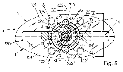
Figure 8 is a partial plan view and partially sectioned view
of an external face of two adjacent heat exchanger modules
that are mutually joined and connected to the connecting
means and the locking means in Figure 7;
Figure 9 is an enlarged and bottom perspective view of a
locking bush for locking the locking means in Figure 7;
Figures 10 and 11 are partial sections enlarged respectively,
along the line X-X and the line XI-XI of Figure 8;
Figure 12 is an enlarged section along the line III-III in
Figure 2;
Figure 13 is a perspective view of a version of the heat
exchanger module, of the connecting means and of the locking
means of the modular heat-exchange system in Figure 1;
Figure 14 is an enlarged partial view of a detail in Figure
13;
Figure 15 is an enlarged partial bottom perspective view of
the heat exchanger module, of the connecting means and of the
locking means in Figure 13;
Figure 16 is partial plan view and partially sectioned view
of two adjacent heat exchanger modules that are mutually
CA 02677431 2009-08-05
WO 2008/102234 PCT/IB2008/000367
8
joined and connected by the connecting means and by the
locking means ;
Figure 17 is an enlarged partial section according to line
XVIII-XVIII in Figure 16;
Figure 18 is a perspective view of radiant means applied to
the heat exchanger module in Figure 13;
Figure 19 is a perspective view of the radiant means in
Figure 18.
In Figure 1 there is illustrated the heat-exchange system of
the invention comprising a plurality of heat exchanger
modules 1, which are joined and connected to form a modular
panel, i. e. a chain or mosaic, which can be positioned on a
wall S of, a room, for example a colder wall facing the
-exterior, to thermally condition the room, taking account of
the volume of the building and of the intended use thereof,
also with reference to the presence of doors, windows and the
possibl,e equipment that may be arranged against said wall S.
The modularity of the heat-exchange system 100 enables a
heat-exchange panel to be made that is customised and
suitable for the needs of the room to be conditioned. The
heat-exchang.e system 100 is applicable not only to surfaces S
of walls,floors or ceilings of a building but also to any
supporting surface intended for positioning in any room to be
thermally conditioned.
The heat exchanger modules 1 are arranged individually for
fixing to the wall S, or to the ceiling or floor of the
building or of prefabricated parts bf the same building, as
explained in detail below in the description.
The heat exchanger modules 1 can for example have a square or
rectangular shape or other shape suitable for the chain or
mosaic composition and are internally provided with channels
or conduits C for circulation of a thermal conditioning
fluid, positioned or leading onto opposite and/or consecutive
sides of said modules.
CA 02677431 2009-08-05
WO 2008/102234 PCT/IB2008/000367
9
Locking means is provided for connecting and fixing in a
reversible manner two heat exchanger modules 1 that are
adjacent in an assembly condition.
Connecting means is provided for sealingly connecting the
ends of the conduits C of the two adjacent heat exchanger
modules l so that, once the heat-exchange system 100 in the
form of a modular panel has been assembled, a circuit C' is
made, for the circulation of the conditioning fluid.
The circuit C' can be supplied by any suitable source and be
connected, for example, to suitable manifolds D, of known
type and not illustrated in detail in the Figures, provided
as a single piece or fitted on one or more of the heat
exchanger modules 1 for connecting to liquid circulation
means, which is also of known type and is not illustrated in
the Figures.
Depending on the intended use of the modular panel 100 to be
formed, the heat exchanger modules 1 may have conduits C that
are shaped according to different methods: rectilinear
conduits open on two opposite sides of the same module, cross
conduits, open on four sides of the module, "T' -shaped
conduits, open on three sides, for example, consecutive sides
of the module, "L"-shaped conduits open on two consecutive
sides of the same module.
With reference to Figures 2 to 6 there is illustrated an heat
exchanger module 1 of the heat-exchange system 100 of the
invention provided with rectilinear conduits, the
constructional features of which also apply to the other
types of heat exchanger modules provided with conduits having
different configurations.
The heat exchanger module 1 comprises a plate 101, for
example made of metal material, in particular of aluminium
alloy, for example made by a die-casting process. The plate
101 is provided with a protruding and continuous perimetrical
edge 201 which gives an internal or rear face 101b of the
module 1 a box-like shape, suitable for containing an
insulating layer 2 of a thermal insulating material with good
CA 02677431 2009-08-05
WO 2008/102234 PCT/IB2008/000367
resistance to compression. The insulating layer 2 combines
raised parts provided on said rear face of the heat exchanger
module 1 and protrudes from the edge, 201 for a defined
portion, for example by overhanging it.
The heat exchanger module 1 is positioned in contact with the
wall or surface S of the building with the internal face lOlb
bearing the insulating layer 2, so that a radiant front
external face lOla, which is opposite said internal face
lOlb, faces the room to be conditioned and the conditioning
heat is not released to/removed from the wall S of the room.
On the internal face 101b of the heat exchanger module 1,
longitudinal walls 3 of the conditioning fluid circulation
conduits C are made monobloc, which may, for example, be at
least two or more in number and thus not necessarily four in
number as illustrated in Figures 2 and 5.
The ends of the conduits C lead onto corresponding apertures
or openings B on the edges 201 of the module 1.
The conduits C are arranged for being closed in the lower
part of the module 1 and the tubular shape thereof is thus
defined by closing elements or bottom 4 sealingly applied by
means of appropriate glue or adhesive.
The closing elements 4 are provided longitudinally with edges
with a grooved profile 104 which are coupled on the edges of
the walls 3 of the conduits C (Figure 6). The ends of the
closing elements 4 comprise flat parts 204 which rest on, and
are fixed to, steps 5 provided at the bottom on the
perimetrical area of the heat exchanger module 1 in which the
openings B of said conduits C are made.
Using monobloc l'ongitudinal walls made on the plate 101
enables conduits C to be made, with a large, for example
almost rectangular, section, in order to have high flow
values of the conditioning fluid with reduced load losses. A
greater flow of the fluid entails higher heat-exchange values
and thus higher performance of the heat-exchange system.
CA 02677431 2009-08-05
WO 2008/102234 PCT/IB2008/000367
11
With particular reference to Figures 5 and 6, the closing
elements 4 are mechanically stiffened by external ribs 6, for
example in the form of a lattice or other suitable shape.
Similarly, further ribs 106, of any suitable form, are
provided on the internal face lOlb of the plate 101. Said
further ribs 106 are connected to the perimetrical edge 201
and also to the longitudinal walls 3 of the conduits C, and
comprise a plurality of conical projections 7, each of which
forms, on the front face 101a of the plate 101 facing the
room, a respective seat or cavity 8.
The aforesaid cavities 8 have, for example, a round section,
form a projection 7 and are preferably open by means of a
respective bottom hole 108. The bottom holes 108 enable
coating means P and/or radiant means 60 to be fixed to the
external face of the heat exchanger module 1.
In the cavities 8 doses of glue 9, for example with a
silicone base, can be applied that are anchored to the bottom
hole 108 and fixed to the mosaic of the plates 101 of the
modules 1, coating means P comprising tiles P or other
suitable coa.ting material.
Some of the cavities 8 can be used differently to fix the
heat exchanger modules 1 of the heat-exchanger system 100 to
the wall S of the room by means of suitable screw anchors 10.
Such screw anchors 10 have a first part 110 that is-mushroom-
shaped and made of suitable-stiff plastics, which is housed
in the cavity 8, reaches as far as the wall S and is crossed
by a fastening screw 210. Further, the screw anchors have a
protruding part 310, which is deformable as said screw 210
expands and which engages a hole 11 made on the wall S with a
drill inserted through the bottom hole 108 of the cavity 8.
The mushroom 110 acts as a spacer inasmuch as it is arranged
not to enter the hole 11 and limit the compressing action
exerted on the thermal insulating layer 2 by the axial stress
of the fastening screw 210 (Figure 4)-.
Spacers 12 can be applied to the bottom of the projections 7
of the cavities 8, inserted, for example by snap-fitting,
CA 02677431 2009-08-05
WO 2008/102234 PCT/IB2008/000367
12
into the hole 108 and arranged for resting on the wall S of
the room without forming heat bridges towards the outside
(Figure 12). When the heat exchanger modules 1 are located on
a floor, the spacers 12 prevent the load exerted on the heat
exchanger modules by walking and by objects subjecting the
insulating layer 2 to excessive and non-distributed pressure
that could subject the modular panel formed by the heat
exchanger modules 1 to uneven stress, especially on the
connecting means.
The spacers 12, which are, for example, made of suitable
stiff plastics, can be provided with a through axial cavity
112 so as to be effectively engaged by the fixing glue 9.
The spacers 12 can further be of the type that is axially
adjustable, for example comprising screw and nut, to be able
to be made to touch the wall S of the room selectively also
when the wall S is not sufficiently flat, for example
comprising rough surfaces.
In the case of the heat exchanger module 1 illustrated in the
Figures, the openings B of the ends of the conduits C lead
onto side walls 113 of recessed seats 13 provided on two
connecting sides 202 that are parallel to and opposit.e the
heat exchanger module 1. Such seats 113 are, for example, two
in number for each connecting side 202, and with each one
thereof two openings B are associated.
Each rectilinear seat 13 is open upwards and on an opposite
side to that of the side wall 113, whilst it is closed below
by a bottom wall 213.
In an assembly configuration AS, in which two heat exchanger
modules 1 are arranged adjacent and are correctly aligned for
mutual fixing, the seat 13 of an heat exchanger module 1 is
opposite the seat 13' of the adjacent heat exchanger module 1
(Figure 8) so as to form a seat or housing 130 that is open
on only one side, perpendicular to the modules, at the
external faces 101a of said heat exchanger modules 1.
CA 02677431 2009-08-05
WO 2008/102234 PCT/IB2008/000367
13
Connecting means 14 is inserted into said housing 130 to
sealingly connect openings B facing and opposite the conduits
C of the aforesaid heat exchanger modules 1.
The connecting means 14 comprises an insert or connecting
element that rests on the bottom walls 213 of the seats 13,
13' and which has through openings 15, having the shape and
dimensions of the openings B of the conduits C. Said through
openings 15 are, further, suitably spaced so as to bridge,
when said connecting element 14 is correctly inserted, the
openings B of the conduits C. Sealing gaskets 16 are provided
frontally around said through openings 15 to ensure a sealing
connection with the openings B (Figure 10). -
The connecting element 14 is provided with an intermediate
part of a central recess 17 suitable for housing a respective
locking bush 19 of the locking means.
The central recess 17 has an enlarged upper portion 117 and a
bottom wall in which-, in a central position, a projection 18
with a substantially circular shape is provided in which a
lower cylindrical hub 119 of a tank or locking bush 19 with a
circular plane can be housed and rotate, the body of the tank
or locking bush 19 rotatably engaging said central recess 17.
Said locking bush 19 comprises a flange or upper wing 219
that engages the widened upper portion 117 of the central
recess 17, and two appendages 319, 319' protrudinglaterally
from a lower part of the body of said locking bush 19. Said
appendages 319, 319' are the same as one another, opposite at
180 and provided with a respective through hole 20.
During the mounting step, when the connecting element 14 is
inserted into the housing 130, i.e. into the seats 13, 13' of
two adjacent and abutting heat exchanger 'modules 1, the
appendages 319, 319' of the locking bush 19 are housed in
slits or lateral grooves 21, 21' of said connecting element
14, open on opposite sides of the connecting element 14
(Figures 7 and 8) , the locking bush 19 being arranged in an
inserting position M.
CA 02677431 2009-08-05
WO 2008/102234 PCT/IB2008/000367
14
In this position, during the assembly step it is possible to
insert inside opposite seats 13, 13' of two adjacent heat
exchanger modules 1 the connecting element 14 and the
corresponding connecting bush 19, joined as if they were a
single piece.
A lateral and central recess 22, 22' having a circular sector
plan shape is provided on each respective seat 13, 13'.
In the assembly condition AS the lateral recesses 22, 22' of
two adjacent seats 13, 13', form with the central recess 17
of the connecting element 14 a complete seat, with a circular
shape, for the locking bush 19.
Each lateral recess 22, 22' comprises a respective upper
widening 122, 122' that is substantially aligned and coplanar
with the widened upper portion 117 of the central recess 17
of the connecting element 14, in the assembly condition AS,
and arranged for receiving the upper flange 219 of the
locking bush 19.
Each upper widening 122, 122' also has a respective' lateral
intermediate extension 222, 222' provided with a respective
vertical through hole 23.
Each lateral recess 22, 22' has a respective side wall
provided with a further slit or groove 24, 24', which is also
of circular shape, that extends for a preset angle and faces
a respective groove 21, 21' of the connecting element 14.
The further grooves 24, 24' of the adjacent seats 13, 13' are
shaped so as to enable the connecting element 14, once it has
been inserted into the housing 130, i.e. into said seats 13,
13', to rotate the locking bush 19 by 90 , from the inserting
position M to a locking position L. In this way, the
appendages 319, 319' are disengaged from the grooves 21, 21'
of the connecting element 14 and are inserted into the
further grooves 24, 24' of the recesses 22, 22' as far as the
locking or closing position L, in which the through holes 20
of the appendages. 319, 319' are substantially aligned on the
through holes 23 of the heat exchanger modules 1.
CA 02677431 2009-08-05
WO 2008/102234 PCT/IB2008/000367
In this locking position L the locking bush 19 is constrained
to the heat exchanger modules 1 by means of the appendages
319., 319' and, at the same time, locks the connecting element
14 in the seats 13, 13', firmly connecting together the heat
exchanger modules 1, which remain joined on a single plane.
It is further possible to firmly fix the locking bush 19 in
the locking position L, by inserting rivets or screws 27 in
the aligned holes 20, 23, as indicated schematically by the
dot and dash lines in Figure 11.
With reference to Figure 9, the locking bush 19 is provided
with abutting means comprising two lower cavities 25, 25',
which are symmetrically the same, the respective external
walls 125, 125' of which have an eccentric shape, i.e. a
variable thickness so as to make an eccentric or cam profile.
When the connecting element 14 and the locking bush 19 in the
inserting position M are inserted into the housing 130 formed
by the two opposite seats 13, 13' of respective heat
exchanger modules 1, the lower cavities 25, 25' are engaged
by further abutting means comprising projections or
protrusions 26, 26' provided on the bottom of the lateral
recesses 22, 22' of the seats 13, 13' and having a bolt
function.
When the locking bush 19 is rotated by ninetydegrees in the
locking position L to fix*the connecting element 14 to the
two adjacent heat exchanger modules 1, the protrusions 26,
26' are engaged progressively by the eccentric external walls
125, 125' of the lower cavities 25, 25' of the locking bush
19 (Figure 11), this causing the twisting or clamping torque
applied to said locking bush 19 to be transformed into
traction force that pushes the heat exchanger modules 1
against the connecting element 14 and against one another.
This compression force ensures an effective and sealing
connection between the openings B of the conduits C and the
through openings 15 of the connecting element 14, with
appropriate compressing of the sealing gaskets 16 (Figure
10).
CA 02677431 2009-08-05
WO 2008/102234 PCT/IB2008/000367
16
This connection has proved to be very reliable and capable of
also resisting very high circulating pressure of the
conditioning fluid.
In order to rotate the locking bush 19, the locking bush 19
is provided, opposite the lower hub 119, with a hexagonal
seat 28 in which a corresponding hexagonal wrench can be
inserted.
With reference to Figure 7, in order to facilitate the
insertion and removal of the connecting element 14 into and
from the housing 130, i.e. the opposite seats 13, 13' of the
two adjacent heat exchanger modules, end walls 114 of said
connecting element 14 can be slightly countersunk or
convergent downwards. Similarly, further end walls 313 of
each seat 13 can be slightly countersunk or divergent from
the bottom wall 213.
With the procedure disclosed above, it is possible to connect
together a plurality of heat exchanger modules 1 and to make
modular panels having various shapes and dimensions.
The heat-exchange system 100 of the invention, owing to the
conformation of the heat exchanger modules 1 and of the
corresponding connecting means 14 and of the locking means 19
enables the heat exchanger modules 1 to be assembled in a
rapid and easy manner that can be fixed independently to the
wall S of the room and then be connected and locked together
by the connecting means 14 and the locking means 19.
Similarly, once the heat-exchange system 100 has been
assembled to form a modular panel of desired shape and size,
it is possible in an equally rapid and easy manner to
separately dismantle an heat exchanger module 1, for example
in order to replace it, without the need to dismantle heat
exchanger modules adjacent thereto.
The heat-exchange system 100 thus ensures extremely easy,
fast and cheap assembly/dismantling procedures.
In addition thereto, the connecting means 14 and locking
means 19 ensure an effective and durable seal between the
conduits C of the various heat exchanger modules 1, also with
CA 02677431 2009-08-05
WO 2008/102234 PCT/IB2008/000367
17
the conditioning fluid supplied at great pressure and
temperatures, for example if the modular heat-exchange system
is associated with a heating boiler operating at high
pressure.
The modular heat-exchange system disclosed can be supplied by
means, of known type that is not illustrated in the Figures,
that provides forced or natural circulation in the conduits C
of a heating or cooling fluid.
Such means comprises boilers, heat pumps, heat exchangers and
the like.
The heat-exchange system 100 of the invention can further be
used as a simple radiator, or heater, visibly applied to a
wall of a room, or as a solar panel to produce hot water by
means of solar radiation, the coating~means P being suitable
for absorbing solar-rays in such a case.
With reference to Figures 13 to.17 there is illustrated a
version of the heat-exchange system 100 of the invention that
differs from the previously disclosed embodiment through the
different configuration of the locking means 419, of the
connecting means 414 and of the seats 413, 413' of the heat
exchanger modules 1.
The connecting means 414 comprises a insert or joint element
that is substantially similar to the previously disclosed
one, provided with through holes 415 and shaped so as to be
inserted inside a housing 430 formed by two opposite seats
413, 413' of two abutting heat exchanger modules 2.
These seats 413, 413' are made, for example, on two parallel
and opposite connecting sides 202 of each heat exchanger
module 1, and are two per side in number.
Each seat 413 comprises a through notch provided with a
lateral wall 513, in which, for example, two openings B of
the conduits C open, and provided with two facing and
opposite end walls 520, shaped to form respective steps. The
end walls 520 are arranged for being engaged in the assembly
condition AS by the further end walls 420 of the connecting
element 414 so as to support the connecting element 414. The
CA 02677431 2009-08-05
WO 2008/102234 PCT/IB2008/000367
18
further end walls 420 are shaped in a complementary manner to
the end walls 520.
The connecting element 414 further comprises a central
through opening 425 in which the locking bush 419 of the
locking means is rotatably inserted.
The locking bush 419 comprises a flange or external wing 519
that is connected, by a central pin 525, to a transverse
plate 526 with an almost rectangular elongated shape.
The flange 519 is provided below with a circular crown 527,
whilst the transverse plate 526 has abutting means 528 on
opposite ends comprising respective protrusions.
The locking bush 419 consists of two couplable parts, so as
to be able to be mounted/dismantled on the connecting element
414, the central pin 525 being rotatably inserted in the
central through opening 425. In particular, the flange 519
and the pin 525 are a single body and are coupled to the
transverse plate 526, for example, by a screw.
Alternatively, the central pin 525 can be formed by two
parts, each of which is made of a single body, respectively
with the external flange 519 and with the transverse plate
526.
The connecting element 414 is provided, on an outer side of
an intermediate part thereof, with a central recess 417
arranged for housing the locking bush 419.
The central recess 417 has peripheral grooves 517, 518
arranged for receiving respectively the flange 519 and the
circular crown 527 of the locking bush 419.
On an opposite internal side of said intermediate portion of
the connecting element 414 there is provided a gap 530 that
is suitable for completely receiving the transverse plate 526
so as to enable the connecting element 414 and the locking
bush 419, mounted thereupon in the inserting position M, to
be inserted inside the housing 430.
On the bottom of the gap 530 two arched grooves 531, 532 are
made that are angularly opposite one another, arrariged for
CA 02677431 2009-08-05
WO 2008/102234 PCT/IB2008/000367
19
receiving respective shaped protrusions 528 of the transverse
plate 526.
A lateral recess 522, 522' is provided on each respective
seat 413, 413' of the heat exchanger modules 1 at the
external face 101a of the heat exchanger module. The lateral
recess 522, 522' has respective peripheral grooves, similar
to those of the central recess 417 and arranged for receiving
respectively the upper flange 519 and the circular crown 527
of the locking bush 419.
In the assembly condition AS the lateral recesses 522, 522'
of two adjacent seats 13, 13' form with the central recess
417 of the connecting element 14 a complete seat, that is
circular in shape, for the locking bush 419.
A notch 426, 426' is.made in the respective seat 413, 413' at
the internal face lOlb of the respective heat exchanger
module 1.
As illustrated in detail in Figure 15, each notch 426, 426'
has an arched shape with, an eccentric profile acting as a
cam. The notches 426, 4261 act as further abutting means for
the abutting means 528 of the locking bush 419.
When the connecting element 414 and the locking bush 419 are
inserted into the housing 530 formed by the adjacent seats
413, 413' of two heat exchanger modules 1 and the locking
bush 419 is rotated by ninety degrees, from the inserting
position M to the locking position L, the shaped protrusions
528 of the transverse plate 526 are disengaged from the
respective arched grooves 531, 532 and are progressively
inserted into the respective notches 426, 426'.
Due to the arched shape with an eccentric profile of said
notches 426, 426', the progressive insertion into the notches
426, 426' of the shaped protrusions 528 causes the two heat
exchanger modules 1' to move towards one another. In this way
twisting or clamping torque applied to the locking bush 19 is
transformed into traction force that pushes and maintains the
heat exchanger modules 1 against one another. Such
compression force ensures an effective and sealing connection
CA 02677431 2009-08-05
WO 2008/102234 PCT/IB2008/000367
between the openings B of the conduits C and the through
openings 415 of the connecting element 414, with an
appropriate compacting of the sealing gaskets 416.
The operation of this version of the modular heat-exchange
system 100 of the invention is substantially similar to that
of the previously disclosed embodiment.
With reference to Figures 18, 19, there is illustrated
radiant means 60 of the heat-exchange system 100 of the
invention.
These radiant means comprise a radiant panel 60 comprising a
slab 61 with, for example, a rectangular or square shape,
provided on an internal surface 61b, opposite a radiant
external surface 61b, of a plurality of elongated ribs or
baffles 62 substantially parallel to one another and to a
side edge 61c of said plate. The baffles 62 are regularly
spaced apart to one another and have, for example, a
corrugated and/or rectilinear shape.
Hooking means 63 is provided on said internal surface 61a to
enable said radiant panel 60 to be fixed to one or more heat
exchanger modules 1.
The hooking means 63 comprises, for example, a plurality of
pegs arranged for engaging the cavities 8 provided on the
external face 101a of the heat exchangers module 1. The pegs
63 are inserted into respective cavities 8 and are fixed by
pressure thereto or by means of interposed glue or another
mechanical means.
Alternatively, the hooking means may comprise one or more
through holes provided on said plate 61 for the passage of
respective fixing screws for fixing to the heat exchanger
modules 1.
Further baffles 64 are provided for connecting together a
series of aligned pegs 63. The further baffles 64 are
parallel to, and are interposed between, the baffles 62.
The radiant panel is made of a metal material, in particular
the same material used for the heat exchanger modules 1, for
example aluminium alloy.
CA 02677431 2009-08-05
WO 2008/102234 PCT/IB2008/000367
21
Once fitted on a respective heat exchanger module (Figure
18), the radiant panel 60, owing to the heat conductivity of
the metal, heats rapidly. The baffles 62 and the further
baffles 64 form a plurality of channels inside which the air
is heated or is cold and through convective motion it is
dispersed into the surrounding environment, ensuring a high
and efficient heat exchange.
The radiant external surface 61a of the panel also enables
heat to be dispersed through radiation.
For this reason, using radiant panels 60 is particularly
suitable for applications of the heat-exchange system 100 of
the invention that provide for the mounting of a plurality of
heat exchanger modules on a substantially -vertical walls of
rooms. The radiant panels are mounted on the heat exchanger
modules so that the baffles 62, 64 are vertical. Each radiant
panel 60 is applicable to a respective heat exchanger module
or to two or more adjacent and interconnected heat exchanger
modules 1.
The external surface 61a of the radiant panel 60. can be
decorated at will to match the,decor of the room in which the
heat-exchange system is inserted.