Note: Descriptions are shown in the official language in which they were submitted.
CA 02677505 2009-09-02
1
TITLE OF THE INVENTION
CONTROLLED VACUUM COLLECTION DEVICE AND METHOD
THEREOF
FIELD OF THE INVENTION
[0001] The present invention relates to device for collecting elements or
items via a vacuum. More specifically but not exclusively, the present
invention
relates to device for collecting items tendered for fare from a transit fare
box.
More particularly but not exclusively, the present invention relates
controlled
vacuum collection devices, systems and methods
BACKGROUND OF THE INVENTION
[0002] A variety of methods and devices for collecting coins and receipts
from the fare boxes of various public transportation vehicles such as buses
are
taught in the art.
[0003] It is known in the art to pneumatically transfer the contents of
the
fare box of a public transit bus to a processing center where the coins are
sorted
according to their denomination into compartments within a vault.
Specifically, a
conduit having a probe at one end is connected to the fare box and sucks the
coins via a vacuum towards a processing center at the other end of the
conduit. It
is also known in the art to transmit the data of the fare box or of the vault
(storage
unit) to a central processing centre which can receive data regarding all
buses and
all routes. In other systems
[0004] A drawback of known systems is that the removal or collection of
coins from the fare box cannot be modulated based on the contents therein
providing systems which are inconvenient and sometimes incapable of removing
CA 02677505 2009-09-02
2
all the contents of the fare box and other times damaging the tickets in the
fare
box by using too much suction.
OBJECTS OF THE INVENTION
[0005] An object of the present invention is to provide a device for
collecting
items from a container.
[0006] An object of the present invention is to provide a system for
controlling the collection of items.
[0007] An object of the present invention is to provide a method of
controlling the collection of items from a container.
[0008] An object of the present invention is to provide a system for
monitoring the amount of items tendered for fare in transit vehicle fare
boxes.
SUMMARY OF THE INVENTION
[0009] In accordance with an aspect of the present invention, there is
provided a device for collecting items from a container, the device
comprising:
[0010] a collection unit for collecting the items therein;
[0011] a conduit in fluid communication with the collection unit and being
mountable to the container so as to be placed in fluid communication
therewith;
[0012] a vacuum producing unit for producing a vacuum within the conduit;
and
[0013] a controller linked to the vacuum producing unit and configured to
acquire data regarding the contents of the container;
CA 02677505 2009-09-02
3
[0014] wherein when receiving data regarding the contents of the
container,
the controller so controls the vacuum producing unit as to modulate the vacuum
produced within the conduit thereby suctioning the items within the container
when
mounted thereto into the collection unit.
[0015] In an embodiment, the controller receives information from the
container via a processor mounted to the container. In the data regarding the
contents of the container comprises the volume of items within the container.
[0016] In an embodiment, after suctioning the items from the container
into
the collection unit, the controller is so configured as to determine the
volume of
the items within the collection unit.
[0017] In an embodiment, the controller modulates the vacuum in the
conduit in accordance with the amount of items in the container.
[0018] In accordance with an aspect of the present invention, there is
provided a system for controlling the collection of items comprising:
[0019] a plurality of the devices of claim 1, each the device for
collecting
items from at least one respective container; and
[0020] a central controller mounted to each the controller of each the
device
for receiving data therefrom regarding the contents of each the at least one
respective container
[0021] In an embodiment, each device provides for collecting items from a
plurality of containers, each controller of each device configured to acquire
data
regarding the contents of each container of the plurality of containers and to
transmit this data to the central controller.
[0022] In accordance with an aspect of the present invention, there is
provided a system for controlling the collection of items comprising:
CA 02677505 2009-09-02
4
[0023] at least one container for placing items therein;
[0024] a processor in communication with the container so as to detect
the
amount of items being placed therein;
[0025] a controller in communication with the processor for receiving
data
regarding the contents of the container; and
[0026] a collection unit linked to the controller for control thereof and
comprising a conduit for being mounted to the container and a vacuum producing
unit for producing a vacuum within the conduit,
[0027] wherein when mounting the conduit to the container, the controller
so controls the vacuum producing unit as to modulate the vacuum produced
within
the conduit in accordance with the received data thereby so as to suction the
item
within the container into the collection unit.
[0028] In accordance with an aspect of the present invention, there is
provided a method of controlling the collection of items from a container, the
method comprising:
[0029] remotely determining the contents of the container;
[0030] placing a collection unit in fluid communication with the
container;
[0031] providing a vacuum between the container and the collection unit
so
that items from the container are suctioned into the collection unit; and
[0032] modulating the intensity of the vacuum in accordance with the
contents of the container.
CA 02677505 2009-09-02
[0033] In accordance with an aspect of the present invention, there is
provided a system for monitoring the amount of items tendered for fare in
transit
vehicle fare boxes, the system comprising:
[0034] a plurality of fair boxes for receiving items tendered for fare
therein,
each the fare box being mounted to a transit vehicle;
[0035] a processor mounted to each fair box for detecting the amount of
items therein; and
[0036] a controller remote from the plurality of fare boxes and in
communication with each processor thereof so as to receive data regarding the
amount of items in each fare box.
[0037] In en embodiment, there is provided a location sensor linked is to
each fare box and in communication with the controller so as to determine the
location of each fare box within a transit circuit and to transmit this data
to the
controller.
[0038] Other objects, advantages and features of the present invention
will
become more apparent upon reading of the following non-restrictive description
of
illustrative embodiments thereof, given by way of example only with reference
to
the accompanying drawings.
BRIEF DESCRIPTION OF THE DRAWINGS
[0039] In the appended drawings:
[0040] Figure 1 is schematic representation of the device for collecting
items I from a container via a controlled vacuum in accordance with a non-
restrictive illustrative embodiment of the present invention;
CA 02677505 2009-09-02
6
[0041] Figures 2 to 8 are schematic representation of the systems for
controlled vacuum collection of items from containers in accordance with
respective non-restrictive illustrative embodiment of the present invention;
and
[0042] Figure 9 is a schematic representation of a system for controlled
vacuum collection of items tendered for fare from transit fare boxes and for
monitoring the location of the fare boxes within a transit route.
DETAILED DESCRIPTION OF ILLUSTRATIVE EMBODIMENTS
[0043] Generally stated, the present invention, in an embodiment, thereof
is concerned with devices, methods and system using frequency communication
for controlled vacuum collection of items from containers. The items can
include
money, coins, receipts, tokens, bills in fare boxes used in transport vehicles
such
as buses. Of course, the present system can be used in other areas as well. In
an
embodiment, the present invention is concerned with a radio frequency
communications device used particularly but not exclusively to transfer
information
relative to a vacuum controlled collection device so as to modulate the vacuum
pressure thereof and as such the collection process itself. The collection
system
provides for collecting the receipts, moneys and coins directly into the
integrated
collection module from the fare box of the transport vehicle without any human
contact therewith. Thus the system includes a collection module that is vacuum
controlled as well as a radio frequency communications device (RF device).
[0044] In an embodiment, the device comprises a collection unit, a vacuum
producing unit, a conduit and a controller. The conduit is connected to the
vacuum
providing unit and is in fluid communication with the collection unit. The
conduit is
also mountable to the container so as to be placed in fluid communication
therewith. The controller is linked to the vacuum providing unit and is
configured to
acquire data regarding the contents of the container. When the controller has
received data regarding the contents of the container it signals the vacuum
CA 02677505 2009-09-02
7
providing unit so as to modulate the created vacuum thereby correspondingly
suctioning the items within the container into the collection unit.
[0045] With reference to the accompanying drawings non-limiting
illustrative
embodiments of the present invention will be described.
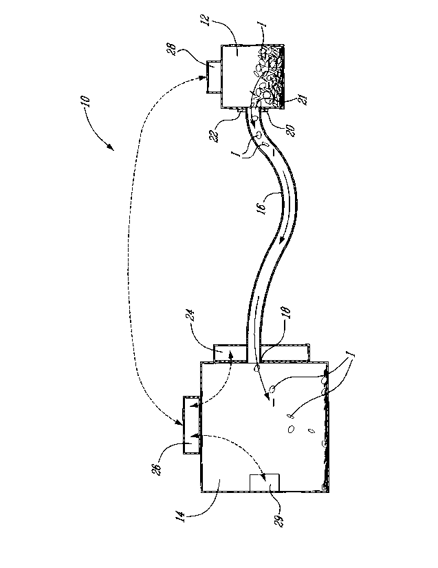
[0046] Figure 1 shows a device 10 for collecting items I from a container
12
such a fare box used in transit vehicles to provide one non-limiting example.
.The
items collected therefore can be items tendered for fare such as currency,
bills,
coins, tickets, receipts, fare cards and the like.
[0047] The device 10 includes a collection unit 14, such a vault. A
conduit
16, such as a hose in fluid communication with the collection unit 14 at on
end 18
thereof. The conduit 16 includes a free end 20 which can be a collection
probe.
The free end 18 includes an opening 21 and is mountable to a mounting element
22 on the container 12. As is known in the art, the mounting element 22 can
include a locked slot, door or cover (not shown) that is opened when the
conduit
16 engages it.
[0048] In other known containers, this door or cover is unlocked and
opened before the conduit 16 engages it. Since fare boxes and security
containers are well known in the art and quite diverse in structure and
configuration, the present container 12 need not be described further. A
variety of
fare box structures known in the art can be provided within the context of the
present invention. It is well known to first mount a vacuum conduit or probe
onto a
locked vault about a probe receiving element surrounding a locked door member
and to then unlock the door member. Of course other types of probes, conduits
and fare boxes can be used within the context of the present invention. For
example, the door element or cover of the out-feed opening can be opened in a
variety of ways before the collection probe or after the collection probe
engages
the fare box.
CA 02677505 2009-09-02
8
[0049] The device 10 includes a vacuum producing unit 24 such as a
vacuum pump or any other pneumatic device that provides for producing a
vacuum as is well known in the art. As is also well known in the art, the
vacuum
producing unit 34 is in communication with the conduit 16 thereby creating a
vacuum therein as well as modulating the intensity of the vacuum as will be
further
explained herein. In the schematic example, the vacuum producing unit 24 is
mounted to the collection unit 14 and as such forms part of this unit 14. The
conduit 16 is thus mounted at it end 18 to the collection unit 14 via the
vacuum
producing unit 24.
[0050] A controller 26 receives information about the contents of the
fare
box 12 via a processor 28.
[0051] Processors for measuring the amount of items within containers are
well known in the art. For example, it is well known in the art to include
fare box
with electronic receiving slots that count the value of the bills or coins or
tokens
placed in the fare box. These fare boxes can track the value of money placed
therein as well as the amount of items that have been collected in terms of
volume
and not value.
[0052] The processor 28 therefore provides the controller 26 with
information regarding the amount of items stored within the fare box 12. More
specifically, the processor 28 transmits information regarding the content
volume
of the fare box 12. The information provided to the controller 60 includes the
amount of receipts, coins, bills, tokens and the like. .
[0053] The controller 26 transmits a control signal to the vacuum
producing
unit 24 and to produce a given vacuum intensity. More specifically and as is
know
in the art, the vacuum producing unit 24 can modulates the intensity of vacuum
produced within the conduit 16. This intensity can be modulated between
relatively high and low vacuum force as well as several intervals
therebetween.
CA 02677505 2009-09-02
9
The controller 26 transmits a signal to the vacuum producing unit 24 to
produce a
vacuum at a given intensity. This vacuum intensity is modulated in accordance
with information received by the controller 36 from the processor 28. As such,
a
controlled predetermined vacuum is provided within conduit 16 which suctions
the
contents out of the fare box 12 and into the collection unit 14.
[0054] Hence, the greater the contents of the fare box 18 the greater the
vacuum needed and vice versa.
[0055] The control unit 14 is also shown including a sensor 29 which
detects the amount of items I therein. The sensor 29 is in communication with
the
controller 26 and provides the foregoing information thereto. As such, the
controller 26 can verify after the above suctioning operation if whether the
volume
of the contents if items I in the collection unit 14 corresponds to the volume
of the
contents in the container 12 preceding the suctioning operation.
[0056] Communication between the controller 26 and the processor 28 and
can be provided by radio frequency (RE) communication or any other like
communication as the skilled artisan will readily appreciate.
[0057] The sensor 29 can be linked to the controller via a wire or
wireless
link.
[0058] The device 10, processor 28 and container 12 provide a system for
controlling the collection of items.
[0059] The controller 24 is shown to be mounted to the collection unit 14
but it can be remote from the unit 14.
[0060] The vacuum producing unit 24 can be integrated to the collection
unit 14.
CA 02677505 2009-09-02
[0061] Figure 2 shows a system 30A for controlled vacuum collection
including a controller 32 (or a microcontroller) being linked via a wireless
connection to a processor 34 linked to a fare box 36 and a collection unit 38
via a
wireless link. The collection unit 38 includes an integrated vacuum producer
modulated by the controller 34.
[0062] Figure 3 shows a system 30B for in which the controller 32 is
linked
to the fare box processor 34 via a communications interface 40 which can be in
the form of an antenna with an integrated circuit for example.
[0063] Figure 4 shows a system 30C for controlled vacuum collection
similar to system 30A and further comprising a position sensor 42 in order to
assess the position of the probe 44 of the collection unit.
[0064] Figure 5 shows a system 30D for controlled vacuum collection
wherein the controller 32 is linked to a plurality of collection units 38 for
modulating the vacuum force produced thereby.
[0065] Figure 6 shows a system 30E for controlled vacuum collection
wherein the controller 32 is linked to a plurality of processors 34 and fare
boxes
36.
[0066] Figure 7 shows a system 30F for controlled vacuum collection
comprising a remote central controller 46 linked to a plurality of controllers
30 for
control thereof.
[0067] Figure 8 shows a system 30G for controlled vacuum collection
similar to system 30F but including a communication interfaces for providing
communication between the controllers 32 and the remote central controller 46.
[0068] Figure 9 shows a system 30H for controlled vacuum collection and
for monitoring the amount of items in transit vehicle fare boxes. The system
30G
CA 02677505 2009-09-02
11
includes a controller 32 linked to the processor 24 of the fare box 36. A
location
sensor 50, such as a GPS, communicates with the processor 24 in order to
determine the location of the fare box 36 along a transit circuit.
[0069] The various systems and devices described above can be combined
in a variety of ways as will be understood by the skilled artisan to provide
still other
non-restrictive illustrative embodiments within the scope of the present
invention.
[0070] In an embodiment, the communication interface 40 receives a signal
from the fare box processor 34 and transmits this signal to the controller 32
which
recognizes the fare box 36 and authorizes collection. The controller 30 then
signals the collection unit 38 as such the collection probe 44 is ready to
engage
the fare box 36. The position sensor 42 recognizes the position of the
collection
probe 44 in order to transmit security instructions to the controller 30. More
particularly, the position sensor 44 determines that the collection probe 44
has
been mounted to the fare box 36. The controller 30 then sends a corresponding
signal to the processor 34 which unlocks the fare box 36 in order to allow for
the
contents therein to be collected.
[0071] In one example, when a vehicle, such as bus, reaches a pre-
authorized zone, such as a collection station, the fare box 36 is
automatically
identified by a code, such as an EPC code which is preprogrammed into the fare
box processor 34 and which can be allotted to a given transport circuit or
route.
[0072] In an embodiment, the location sensor 50 recognizes that the bus
has reached the pre-authorized zone and sends this information to the
controller
30.
[0073] The processor 34 transmits data concerning the contents of the fare
box 36, in relation to its volume, density and EPC code to the controllers 30.
The
CA 02677505 2009-09-02
12
controller 30 receives and processes the foregoing data in order to transmit
it, via
the communications interface 48, to the central controller 46.
[0074]
Therefore, once the fare box 36 of the vehicle has been identified
and its contents evaluated, the vacuum can be adjusted and the contents are
suctioned into the collection unit 38.
[0075]
Furthermore, the central controller 46 receives information from
each and every controller 32 and thus determines in real time the contents of
each
fare box 36 that is related to a given route as well as the amount of users
that
used that said route for different bus schedules (which can be determined at
an
hourly, daily, monthly, yearly etc. basis). Location sensors can monitor the
location
of each fare box 32 on a given vehicle within a given transit circuit.
Moreover,
information regarding the contents and location of the fare boxes 36 can be
combined at the central controller 46 which receives real time information
regarding the contents and location of each and every fair box.
[0076] In
addition, the central controller 46 can receive information
regarding the transfer of items I (see Figure 1) from the fair box 36 to the
collection unit 38 via a sensor 29 (see Figure 1).
[0077] The
skilled artisan will readily appreciate that variations of the all the
foregoing information can be combined in various ways in order to provide a
variety of accounting or assessment packages providing for producing
statistical
reports concerning the amount of users during various routes and various
travel
schedules as well as the efficiency of collection of items tendered for fare
[0078]
Nevertheless, it should be noted that the above described controlled
vacuum suction systems can be used for other applications.