Note: Descriptions are shown in the official language in which they were submitted.
CA 02677617 2009-08-06
WO 2009/006524 PCT/US2008/069026
PRESSURE INTERFERENCE TESTING FOR ESTIMATING HYDRAULIC
ISOLATION
Field of the Invention
[0001] The invention is generally related to oil and gas wells, and more
particularly to determination of the integrity of cement between two points in
a
borehole as indicated by permeability or transmissibility.
Background of the Invention
[0002] Geological sequestration of CO2 is currently being studied as a
possible
method for mitigating the rapid rise of greenhouse gases in the atmosphere.
For
example, CO2 might be sequestered in the permeable layers of formations
associated
with oil and gas wells. Such the permeable layers are typically located
beneath an
impermeable layer which forms a natural barrier against upward movement of the
CO2. Well boreholes provide a pathway for moving CO2 into the permeable layer.
However, it is possible for leakage pathways to form through the cement
annulus
between the well casing and the formation. Cement, in a multitude of reaction
steps,
has been demonstrated to deteriorate and form CaCO3 in the presence of CO2 and
water (see Ch. 7 Special Cement Systems, by E. B. Nelson et al., Cement
Handbook,
section on Cements for Enhanced Oil Recovery by C02-Flooding). In order for
long
term CO2 storage to be practical, relatively little of the injected gas can be
permitted
to leak back into the atmosphere (see IPCC's special report on carbon dioxide
capture
and storage, pg 197, 2006). It is therefore desirable and important to know
the quality
1
CA 02677617 2009-08-06
WO 2009/006524 PCT/US2008/069026
of the cement in a formation selected for CO2 sequestration, both before and
after
injection of CO2.
[0003] Until now, formation tests have been designed to measure the
permeability of a reservoir. Although quantifying skin is a common practice in
well
testing, and it may be appealing to regard cement as a skin, conventional skin
estimation procedures work only when skin is sufficiently transmissible, i.e.,
the skin
zone permeability is not orders of magnitude smaller than that of the
formation. The
reason for this is the skin zone is treated as being in pseudo-steady state,
i.e., pressure
drop across the skin region is directly related to flux (van Everdingen, A.F.
1953, The
Skin Effect and its Influence on the Productive Capacity of a Well, Trans.
AIME, 198,
171--176). Consequently, existing techniques are not entirely suited to
estimating
degradation of cement.
Summary of the Invention
[0004] In accordance with one embodiment of the invention, a method of
estimating hydraulic isolation between first and second points in a material
under test
that is disposed between a hydraulically impermeable barrier and a geological
formation comprises the steps of: forming first and second openings in the
hydraulically impermeable barrier adjacent to the first and second points
under test,
the openings being formed up to, but not completely through, the material
under test;
causing a change in pressure at the second opening; at the first opening,
measuring
transmission of the pressure change across the material; and storing the
measured
pressure change for estimating hydraulic isolation between the first and
second points.
[0005] In accordance with another embodiment of the invention, apparatus for
estimating hydraulic isolation between first and second points in a material
under test
2
CA 02677617 2009-08-06
WO 2009/006524 PCT/US2008/069026
that is disposed between a hydraulically impermeable barrier and a geological
formation comprises: an ablating component operable to form first and second
openings in the hydraulically impermeable barrier adjacent to the first and
second
points under test, the openings being formed up to, but not completely
through, the
material under test; a probe operable, when set at the first opening, to
measure
transmission of a pressure change across the material in response to a change
in
pressure at the second opening; and a memory operable to store the measured
pressure
change, from which hydraulic isolation between the first and second points is
estimated.
[0006] In accordance with another embodiment of the invention, apparatus for
generating a pressure pulse of known magnitude comprises: a first chamber
filled with
an incompressible fluid; a second chamber filled with a gas, the second
chamber
hydraulically linked with the first chamber; a third chamber filled with an
incompressible fluid, the third chamber hydraulically linked with the second
chamber;
a fourth chamber filled with an incompressible fluid, the fourth chamber
hydraulically
linkable with the third chamber via a first valve; means for sensing pressure
in the
third chamber; and means for sensing pressure in the fourth chamber, whereby a
pressure pulse of a magnitude corresponding to the sensed pressure
differential
between third chamber and the fourth chamber with the valve closed can be
generated
by opening the valve.
[0007] In accordance with another embodiment of the invention, a method for
generating a pressure pulse of known magnitude comprises: with a tool having a
first
chamber filled with an incompressible fluid, a second chamber filled with a
gas, the
second chamber hydraulically linked with the first chamber, a third chamber
filled
with an incompressible fluid, the third chamber hydraulically linked with the
second
3
CA 02677617 2009-08-06
WO 2009/006524 PCT/US2008/069026
chamber, a fourth chamber filled with an incompressible fluid, the fourth
chamber
hydraulically linkable with the third chamber via a first valve, means for
sensing
pressure in the third chamber, and means for sensing pressure in the fourth
chamber,
with the first valve in a closed state, creating a pressure differential
between third
chamber and the fourth chamber and, generating a pressure pulse of a magnitude
corresponding to the sensed pressure differential by opening the first valve.
[0008] Further features and advantages of the invention will become more
readily
apparent from the following detailed description when taken in conjunction
with the
accompanying Drawing.
Brief Description of the Drawing
[0009] Figure 1 illustrates a pressure tester tool utilized in a borehole to
determine cement integrity adjacent to a permeable layer.
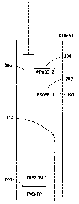
[0010] Figure 2 illustrates a multi-probe pressure test tool.
[0011] Figure 3 illustrates a mechanism for generating a pressure pulse of
known
magnitude.
[0012] Figure 4 illustrates a single-probe pressure test tool.
Detailed Description
[0013] Referring to Figure 1, a pressure tester tool (100) is utilized to test
the
integrity of cement (102) in a well completion. The pressure tester tool is
secured to a
spool (104) of cable located at the surface. The cable is spooled out in order
to lower
4
CA 02677617 2009-08-06
WO 2009/006524 PCT/US2008/069026
the pressure tester tool (100) into the borehole to a desired depth, e.g.,
above a
permeable layer (106) into which CO2 has been, or might be, injected. The
pressure
tester is in communication with a control unit (108) located at the surface
via
electrical, optical, wireless, or other suitable communications links, through
which
data and instructions may be transmitted and received. In the illustrated
embodiment,
the pressure tester tool is responsive to instructions transmitted from the
control unit
(108), and transmits pressure data to the control unit in real time. Although
a
tethering cable is shown, the pressure tester tool could be permanently
installed in the
borehole. Alternatively, the pressure tester might operate autonomously, and
might
accumulate data in memory for subsequent retrieval, e.g., when brought to the
surface.
[0014] The formation surrounding the borehole includes the hydraulically
permeable layer (reservoir) (106) adjacent to an impermeable layer (110) or
seal, and
various other layers which make up the overburden (112) (not shown to scale in
Fig.
1). The permeable layer (106) is, potentially at least, utilized for carbon
sequestration. The borehole is equipped with a completion which functions to
maintain the structural integrity of the borehole within the formation. The
completion
also provides a hydraulic barrier between the formation and the borehole. In
the
illustrated embodiment the completion includes a tubular casing (114), which
may be
constructed of metal, fiberglass, or other substantially hydraulically
impermeable
material. The completion also includes cement (102) which is disposed in the
annulus
between the casing (114) and the formation (110). Ideally, the cement (102)
should
be structurally sound in order to prevent CO2 leakage. The pressure tester
tool is
utilized to determine the integrity of the cement, particularly in the area
above the
permeable layer (106).
CA 02677617 2009-08-06
WO 2009/006524 PCT/US2008/069026
[0015] Operation of one embodiment of the tester tool (100a, Figure 2) will
now
be described with reference to Figures 1 and 2. Because of the relatively
large
diameter of the tester tool relative to the inner diameter of the casing, any
injection
tubing that is present may have to be pulled out before testing begins. A
first packer
(200) is set to close when the tubing is pulled out, and if necessary, a
second packer is
also set above the tubing packer (200). Typically, the annular cement (102)
will be
saturated with water as its pore fluid. In order to reduce tool storage
induced delay
and obtain the correct borehole pressure gradient, both the tool (100a) and
the
borehole are filled with brine in preparation for testing. This may be
accomplished in
a number of ways, including flushing the flowline with the borehole fluid
after
opening the hydraulic lines to the borehole. Alternatively, the tool may also
be
flushed at the surface. It is desirable that all residual gas in the tool flow
lines are
flushed out.
[0016] Holes are formed through the casing in order to prepare for a test of
the
integrity of the cement. The holes may be formed by mechanical, electrical,
chemical
or laser ablation. In the illustrated embodiment, the tool drills
(mechanically) through
the casing (114) with a bit in a first location in order to establish
hydraulic
communication with the cement (102). The drilling is stopped at the cement
interface
with the casing. This may be accomplished based on the known casing thickness,
and
by monitoring the torque on the drill bit. In particular, an initial increase
in drill bit
torque is indicative of contact with the casing, and a subsequent sudden
change in the
torque is indicative of the drill bit having reached the cement-casing
interface. The
length of travel of the drill bit (or quill) between torque gradient events
may also be
measured against the known casing thickness to verify or determine when to
cease
drilling. Drilling may continue some distance into the cement, but only to a
distance
6
CA 02677617 2009-08-06
WO 2009/006524 PCT/US2008/069026
smaller than the cement thickness such that the formation is not reached. In
the
illustrated embodiment, penetration of the drill bit into the cement is
limited to a
minute fraction of the overall thickness of the cement.
[0017] Once the hole has been drilled at the first location, a "sink" probe
(202) is
set at that location. The probe includes a seal which, when the probe is set,
hydraulically isolates the probe sensor from the borehole fluid. Nevertheless,
the set
probe may read the cement fluid pressure as being about the same as the
borehole
pressure (equal to the brine column in gauge pressure) and, in the absence of
any
cement permeability, continue to hold this pressure. A slow drift suggests
minor
permeation through the cement, and that the fluid pressure in the cement
column is
different from that of the hydrostatic column pressure. This may occur due to
pressure anomalies in formation layers. If no noticeable trend in pressure is
seen
upon setting the first probe, two possibilities arise: (i) no measurable
hydraulic
communication is present in the cement; or (ii) cement fluid is close to the
borehole
fluid pressure. The latter may be tested by adding more borehole fluid as
explained in
greater detail below and, if no observable trend in pressure exists, increased
likelihood
of the first possibility is indicated. One advantage to filling the borehole
entirely with
brine is that this will give a pressure equivalent to an entire hydrostatic
column.
[0018] It is preferable for testing purposes that the borehole pressure be as
close
to the native cement fluid pressure as practical. One technique for
accomplishing this
is to start with a borehole fluid level height corresponding to a pressure
that is slightly
lower than the expected cement pressure. The probe is set first, and if there
is an
upward drift in pressure, the probe seal is relaxed, and more borehole fluid
added.
The probe is then set again, and the pressure trend noted. The cycle may be
repeated
as many times as necessary to achieve equalization, noting that each foot of
water
7
CA 02677617 2009-08-06
WO 2009/006524 PCT/US2008/069026
column height corresponds to about 0.43 psi of pressure increase at the bottom
of the
borehole.
[0019] Once the pressure drift is found to be small, and within acceptable
range,
a second (observation) probe (204) is set. Setting the probe includes
hydraulically
sealing the probe against the casing. The second probe should be in
hydrostatic
equilibrium with the first probe. After both probes are set, the internal
hydraulic
communication between the probes is terminated with an isolating valve. Note
that
the observation probe may be offset either horizontally, or vertically, or
both.
Further, multiple observation probes may be set in any combination of offsets.
[0020] Once the sink and observation probes are set, a pressure pulse is
induced
in the "sink" probe (202). The pressure pulse may be generated by a fixed
pressure
increase within the tool. The observation probe (or probes) are monitored for
a
responsive pressure signal. If a pressure pulse is observed at the observation
probes,
poor hydraulic isolation in the cement is indicated. The decay of the pressure
within
the pulsed probe as well as any observed pulse in the offset observation
probe(s) may
be used to adjudicate the effectiveness of cement isolation. In particular,
the
hydraulic isolation can be quantified based on the difference in time between
the
pressure pulse and the responsive pressure signal. In this manner the cement
transmissibility and permeability may be calculated.
[0021] Those skilled in the art will recognize that it is quite difficult to
control the
pressure pulse with hydraulic lines filled with brine. An embodiment of a
mechanism
for reliably generating a pressure pulse of known magnitude is illustrated in
Figure 3.
The illustrated pulse generator includes an isolation valve (V1) that may be
actuated
during testing in response to commands from either the control unit or the
tool itself.
Opening the isolation valve allows the brine in chamber (312) to hydraulically
8
CA 02677617 2011-01-10
69897-120
communicate to an air filled chamber (302) through a floating piston (308).
Hydraulic oil in chamber (306) may be pumped on one side of the floating
piston
(304), which has stops on either side. A second piston (308) separates the air
from the
brine in a brine chamber (310) and the brine line (chamber) (312) to the
probe. The
second piston also has two stops, one of which it shares with the first
piston.
[0022] In order to prepare to generate the pressure pulse, isolation valve (V
1) is
open and valve (V2) is closed. Valve (V2) should be as close to the probe as
practical. Initially, the pressure is built in the probe line by pumping
hydraulic oil
into chamber (306), which compresses the air in the chamber, and which in turn
builds pressure in the probe hydraulic line (312). When the pressure is built
sufficiently (e.g., a few hundred psi, at most), the pumping is stopped and
valve (V 1)
is then closed. In order to determine when the pressure is built sufficiently,
pressure
is monitored at one or more pressure sensors (P) and (P1). Valve (V2) is then
opened
in order to generate the pressure pulse. The resulting pulses in the pulsing
probe as
observed by pressure sensor P, and the pressure sensor P in a chamber (not
shown)
associated with the observation probe 1) may be differentiated and correlated,
and the
correlation time should be directly related to the permeability of cement.
Detailed
modeling will yield the exact nature of this correlation. The principles
behind such
correlations for a vertical well in an infinite medium are illustrated in
published U.S.
patent application 20050270903, and in an SPE paper, T. S. Ramakrishnan and B.
Raghuraman, 2005, A Method for Continuous Interpretation of Permanent
Monitoring
Pressure Data, presented at the SPE/ATCE Annual meeting, SPE90910.
[0023] An alternative embodiment does not have valve (V2). In this embodiment
the pressure buildup in the probe (at the cement interface) is relatively
gradual, and
9
CA 02677617 2009-08-06
WO 2009/006524 PCT/US2008/069026
will depend on the pumping rate of the hydraulic fluid and the compressibility
of the
air. Any inability to build pressure in this line implies continuous leakage
of liquid
into the cement, and if the pistons top out, it clearly indicates a complete
disintegration or lack of cement at the zone of interest.
[0024] Testing in a monitoring well should be similar to that of the injection
well
if the well is perforated and has tubing. If the well has no tubing, and there
are no
perforations, assuming the diameter of the well will accept a cased hole
formation
tester, a packer is set below the test zone. As in the injection well, the
well is filled
with brine. The test then follows that of the procedure in the injection well.
[0025] Referring now to Figure 4, in an alternative embodiment of the test
tool
(100b), only one probe (400) is needed. As in the previously described
embodiment,
at least one packer (200) is set so that the bottom section of the borehole is
sealed off.
The probe (400) is initially set at a location (402), and a hole is drilled
through the
casing (114) to the cement (102). Fluid pressure (measurable only when the
cement
has a measurable permeability) is obtained by letting the probe come to
equilibrium,
as evidenced by an imperceptible decay in pressure. As discussed above, if the
cement fluid pressure is measurable, the level in the borehole is adjusted so
that the
wellbore fluid pressure is in equilibrium with cement fluid pressure.
[0026] The next step is to retract the probe (400) from the wellbore and set
it at
an offset location (404), i.e., either horizontally or vertically displaced.
Once the
probe is set at an offset location (404), additional fluid is added to the
borehole, or the
borehole pressure is raised through air pressure at the top of the wellbore. A
pressure
increase of 10 psi may be adequate. An increase in the bottom hole pressure
corresponding to the hydrostatic head therefore occurs. The pressure increase
is
communicated to the cement fluid through the hole drilled through to the
cement in
CA 02677617 2009-08-06
WO 2009/006524 PCT/US2008/069026
the first location. If the cement between locations (402) and (404) has a
permeability
at all, then location (404) would be found to have a slow and steady pressure
increase
from which the transmissibility between (402) and (404) may be inferred. In
particular, the pressure increase over a period of time is matched with a
pressure
response over a period of time, and the time differential between the pressure
increase
and pressure response is indicative of transmissibility.
[0027] In the absence of tubing and perforations in the monitoring well, a
packer
is first installed in the casing adjacent to a shale layer above the formation
that had
CO2 uptake. The remainder of the testing is carried as already described
above.
[0028] While the invention is described through the above exemplary
embodiments, it will be understood by those of ordinary skill in the art that
modification to and variation of the illustrated embodiments may be made
without
departing from the inventive concepts herein disclosed. Moreover, while the
preferred embodiments are described in connection with various illustrative
structures, one skilled in the art will recognize that the system may be
embodied using
a variety of specific structures. Accordingly, the invention should not be
viewed as
limited except by the scope and spirit of the appended claims.
11