Note: Descriptions are shown in the official language in which they were submitted.
CA 02679111 2012-02-15
DESCRIPTION
METHOD OF MAKING A NATURAL RUBBER VACUUM BAG BY SPRAY
PROCESSES, NATURAL RUBBER VACUUM BAG MADE USING SPRAY
PROCESS, AND METHOD FOR USING NATURAL RUBBER BAG MADE
USING SPRAY PROCESS
TECHNICAL FIELD
The subject matter described herein relates generally to the field of
vacuum bag construction. More particularly, the subject matter described
herein relates to methods for making a natural rubber vacuum bag operable for
use in vacuum-assisted resin transfer molding, debulking, compaction, or
similar processes, a natural rubber vacuum bag made by spray processes, and
a method for using a natural rubber vacuum bag made by spray processes.
BACKGROUND
Composites are defined broadly as the combination of two or more
dissimilar materials to produce a new material that has synergistic properties
that were not present in the individual constituents alone. In practical
terms,
the word composite is generally associated with reinforced plastic material
such
as fiberglass structures. In the case of fiberglass, beneficial synergistic
properties including corrosion resistance, low weight, high strength, and low
cost are attainable in a highly variable array of product geometries.
Fabrication of a composite article such as a fiberglass boat hull requires
the combination of a solidifiable resin system with a "preform" that could
include
glass fibers, veils, flow media and cores. There are many processes available
for the purpose of impregnating a preform with liquid resin in order to make a
composite. These processes may be broadly characterized into two
categories, wet lay-up "open molding" and resin infusion "closed molding."
-1-
CA 02679111 2009-08-24
WO 2008/103485 PCT/US2008/002427
Open molding processes tend to produce a final component having a
low fiber volume fraction (i.e., lower relative amount of fiber compared to
the
amount of resin). They are also labor intensive to manufacture because each
layer of preform material must be individually coated with resin and carefully
positioned by hand. Further, the inherent nature of open molding processes
can allow air bubble entrapment to occur inside the composite, and the
completed part can have a non-uniform thickness and fiber volume fraction.
In addition, open molding often leads to direct worker exposure to
Volatile Organic Compounds (VOC) and Hazardous Airborne Pollutants (HAP).
Both VOC and HAP are recognized by the EPA as potential health hazards for
which alternative control technologies should be sought. As a result, although
exceptions can be found, these deficiencies generally result in articles
formed
by open molding techniques being disfavored where other methods are
available.
By comparison, closed molding - and more particularly resin transfer
molding (RTM) - overcomes many of the limitations of wet lay-up processes.
RTM involves a preform being constrained under pressure within a mold cavity
whereupon resin is forced into the open spaces remaining. Resin infusion
methods limit exposure to VOC and HAP and allow for better control over part
dimensions and fiber volume fraction. RTM molds are typically made from
matched steel mold platens which are supported in a hydraulic press due to the
high injection pressures required to force resin through a highly compacted
preform. The escalating cost of fabricating rigid molds for parts in excess of
about 100 square feet tends to limit the size of parts considered for RTM.
Vacuum Assisted Resin Transfer Molding (VARTM) is a variation of RTM
that achieves preform compaction by removing air located between a single
sided rigid tool and a flexible vacuum bag that encapsulates a preform placed
on the tool. Tooling costs are significantly reduced because there is only one
tool surface and atmospheric pressure replaces the hydraulic press. VARTM
provides a closed mold solution for complex and/or large parts that were
previously not considered infusable. A desirable element of a VARTM mold is
a vacuum bag that has sufficient elasticity to accommodate the strains
associated with preform compaction as air is removed. It is further desirable
for
-2-
CA 02679111 2009-08-24
WO 2008/103485 PCT/US2008/002427
the vacuum bag to be sufficiently impermeable so that air does not leak
through the bag and adversely affect the flow of resin or leave air pockets
within the composite product. A vacuum bag should also provide a sufficiently
snug fit around a preform to prevent the formation of creases and/or bridges
which can become resin runners leading to inconsistent flow fronts.
The most common vacuum bag currently used for VARTM is a single-
use Nylon film, and variations are available with more or less stretch, heat
resistance, tear strength and thickness. Films are sold in flat sheet stock
requiring fabricators to cut, paste and seam sections together as needed to
build a suitable vacuum bag. While suppliers are now offering the convenience
of thermally seamed near net shape film bags, Nylon films are not reusable and
thus end up in the dump after each mold run. Furthermore, disposable bags of
this kind rarely provide sufficient elasticity to eliminate bag bridging and
or
bulging which can lead to inconsistent infusions and dry spots in the molded
composite article.
The composites industry is beginning to recognize that reusable vacuum
bags are a desirable component of economically viable production closed
molding programs, with bag longevity being a key factor. Reusable bags must
withstand significantly more wear and abuse than disposable bags. A variety of
Synthetic rubbers have been used to make reusable vacuum bags, including
calendared rubber sheets of EPDM, Silicone, butyl, fluoroelastomers, nitriles
and polyisoprenes and room temperature vulcanizing (RTV) silicones, all of
which originate from a petroleum feed stock.
For reasons of transparency and the ability to make near net shape
constructions, RTV silicone systems have become the material of choice for
making reusable vacuum bags. Vacuum bags made from calendared silicone
sheets require seam treatments of either RTV silicone or a beta staged
silicone
material that must be subsequently cured with heat and moisture. Reusable
bags are also made from semi-cured silicone sheet stock that is cut into
desired shapes, draped in place on the mold surface upon which the seams
are troweled over to create low profile joints. Another method involves
spreading an uncured thixotropic RTV silicone liquid uniformly over a mold
-3-
CA 02679111 2009-08-24
WO 2008/103485 PCT/US2008/002427
surface prior to curing it. In all of these instances, the procedure for
building a
reusable silicone vacuum bag is tedious and requires skilled labor.
Silicones have poor puncture and tear resistance, however, and
therefore must be reinforced or thickened for durability, which makes them
susceptible to the bridging effect in addition to being unnecessarily heavy
and
cumbersome to manipulate. For very large parts such as boat hulls, bridge
decks, and wind blades, the weight of a given bag can become a significant
issue. Large bags often need to be lifted mechanically and therefore require
lift
points. Bag strength becomes a critical factor because thicker bags weigh
more and droopy bags can get caught on foreign objects and become
damaged.
Attempts have been made to spray silicone rubbers with mixed results.
Typical RTV silicones have high viscosity and are thixotropic which makes
them difficult to spray because the material does not flow easily. It is thus
difficult to achieve uniform bag thicknesses over large areas because the
product must be toweled out after being applied to the surface. It is possible
to
reduce the viscosity of RTV silicones with the addition of solvents, but this
remedy has the potential to become a source of VOC and HAP. Spray
equipment that atomizes the silicone also runs the risk of contaminating the
surfaces of neighboring articles exposed to the overspray and can become a
major problem for adhesive bonding and/or painting operations carried out in
the vicinity.
In light of the factors that should be considered when fabricating a
composite article, there still exists a need for a durable, reusable vacuum
bag
for use in closed molding and vacuum bagging applications that limits the
production of VOC and HAP and minimizes the overall environmental impact.
SUMMARY
The subject matter described herein includes methods for making a
natural rubber vacuum bag operable for use in closed molding and other
vacuum bagging applications, a natural rubber vacuum bag made using such
methods, and methods for using such a natural rubber bag to form a composite
article.
-4-
CA 02679111 2009-08-24
WO 2008/103485 PCT/US2008/002427
According to one aspect, the subject matter disclosed herein includes a
method of making a membrane for use as a vacuum bag, including providing a
substantially non-porous working surface having a desired shape for forming a
vacuum bag, spraying at least one layer of a natural rubber liquid over at
least
a portion of working surface, and solidifying the natural rubber liquid to
form a
membrane having a shape substantially corresponding to that of working
surface. By this method, the membrane formed is near net shape, elastically
deformable and substantially impermeable and is thus operable for functioning
as a vacuum bag.
According to another aspect, the subject matter disclosed herein
includes a method for using a vacuum bag to compact a preform. In this
aspect, the method includes providing a substantially non-porous working
surface having a desired shape of a vacuum bag, spraying at least one layer of
a natural rubber liquid over working surface, and solidifying the natural
rubber
liquid to form a membrane. Accordingly, the membrane formed is elastically
deformable and substantially impermeable. Further, the method includes
providing a substantially non-deformable base surface having a desired shape
of a compacted preform, sealing a preform between the base surface and the
membrane, and removing air from between the base surface and the
membrane to draw together the base surface, the preform, and the membrane.
As a result, the preform conforms substantially to the desired shape of the
compacted preform. The method can further include infusing the preform with
resin and solidifying the resin to create a composite article.
According to yet another aspect, the subject matter disclosed herein
includes a method for making a composite article, including sealing a spray-
formed natural rubber membrane to a mold having a desired shape for making
a composite article, evacuating air from a region defined by the membrane and
a preform, flowing a solidifiable resin in the region, and solidifying the
resin to
form the composite article.
BRIEF DESCRIPTION OF THE DRAWINGS
Embodiments of the subject matter described herein will now be
explained with reference to the accompanying drawings, of which:
-5-
CA 02679111 2009-08-24
WO 2008/103485 PCT/US2008/002427
Figure 1 illustrates an arrangement for performing the method of making
a natural rubber vacuum bag by spray processes according to an embodiment
of the present subject matter;
Figure 2 illustrates an arrangement for performing the method of making
a natural rubber vacuum bag by spray processes according to another
embodiment of the present subject matter;
Figure 3 illustrates an arrangement for performing the method of making
a natural rubber vacuum bag by spray processes according to yet another
embodiment of the present subject matter;
Figure 4 illustrates an arrangement for performing the method of making
a natural rubber vacuum bag by spray processes according to still another
embodiment of the present subject matter;
Figures 5 and 6 illustrate the incorporation of one or more articles in a
spray-formed vacuum bag according to an embodiment of the present subject
matter;
Figure 7 illustrates the incorporation of one or more surface features in a
spray-formed vacuum bag according to an embodiment of the present subject
matter;
Figure 8a and 8b illustrate the incorporation of one or more surface
features to measure bag deformation in a spray-formed vacuum bag according
to an embodiment of the present subject matter;
Figure 9 illustrates the use of one or more surface features for the
alignment of spray-formed vacuum bag sections according to an embodiment
of the present subject matter; and
Figure 10 illustrates an arrangement for making a structural article
according to an embodiment of the present subject matter.
DETAILED DESCRIPTION
Reference will now be made in detail to possible embodiments of the
present subject matter, one or more examples of which are shown in the
figures. Each example is provided to explain the subject matter and not as a
limitation. In fact, features illustrated or described as part of one
embodiment
can be used in another embodiment to yield still a further embodiment. It is
-6-
CA 02679111 2009-08-24
WO 2008/103485 PCT/US2008/002427
intended that the present subject matter cover such modifications and
variations.
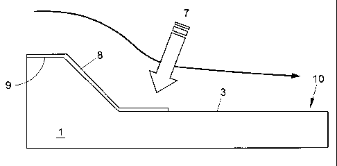
According to one embodiment, the present subject matter provides a
method of making a membrane for use as a vacuum bag. As is depicted in
Figure 1, the method includes providing a substantially non-porous working
surface 10, which in this illustration coincides with a mold surface 3 of a
mold 1,
such surfaces generally being smooth and non porous in nature. Working
surface 10 defines the size and shape of a vacuum bag membrane 20 formed
thereon when a liquid natural rubber 7 is sprayed on working surface 10
leaving
a liquid natural rubber layer 8 which dries to form natural rubber vacuum bag
membrane 20. Correct sizing of vacuum bag membrane 20 helps to eliminate
bridging, where the bag material does not completely conform to concave mold
transitions, and creasing, where excess bag material folds over on itself to
form
an undesirable cavity. In the context of resin transfer molding of composite
articles, each of these fitting problems can lead to non-uniform fiber volume
fractions, higher resin usage, heavier parts, and loss of control over resin
flow
fronts during infusion.
Figure 2 illustrates a method of ensuring that the completed vacuum bag
membrane 20 is properly sized for its intended use. In this alternative,
working
surface 10 is formed by first placing a working surface template 2 on a mold
1,
a surface of working surface template 2 having substantially the exact shape
desired for vacuum bag membrane 20. Working surface template 2 can be an
actual part or a replica of the part that will be molded using vacuum bag
membrane 20 on mold 1. When the surface of working surface template 2 is
porous or cannot readily be made smooth it is difficult to apply liquid
natural
rubber 7 in uniform layers using a spray process. Therefore, working surface
can be made substantially smooth and non porous by covering up the
defective working surface with a thin flexible film 12. Suitable films can
include
thin silicone sheet, urethane film, high elongation nylon film and a thin
natural
rubber sheet produced according to the presently disclosed method. Flexible
film 12 can be sealed around its perimeter using perimeter seals 13 located on
a mold flange 9 or in another suitable location on mold 1. A buffer layer 11
can
be placed on the defective working surface and underneath flexible film 12.
-7-
CA 02679111 2009-08-24
WO 2008/103485 PCT/US2008/002427
The buffer layer 11 can be, for instance, a thin flexible blanket that is
sufficiently permeable to serve as a breather when placed under flexible film
12
such that flexible film 12 can be drawn tightly over working surface template
2
by removing air from of the cavity formed between mold 1 and flexible film 12.
Regardless of which method is used to form working surface 10, it is
further provided that working surface 10 should be substantially non-porous
and generally smooth. Any roughness or surface features on working surface
can transfer to the surface of vacuum bag membrane 20, which can then
transfer ad infinitum to every subsequent part molded with vacuum bag
membrane 20.
Another means of providing a substantially non-porous working surface
10 is to spray or brush a tooling gelcoat or surface primer such as Duratec
High
Gloss on working surface template 2. It is helpful if the gelcoat or primer
material is self leveling and fast drying. Alternatively, if a thicker layer
is
required, it is possible to first spray a foam layer down and then apply a
gelcoat
or primer layer to seal the pores and provide a smooth working surface 10.
Once working surface 10 is prepared, the method can further include
spraying at least one layer of a natural rubber liquid 7 over at least a
portion of
working surface 10. Natural rubber is not considered a toxic material and it
can
be cleaned up with distilled water, resulting in a more advanced "green
technology" than the current art for applying other elastomers (e.g.,
silicone) to
construct mold bags or films. Natural rubber is quite distinct from synthetic
rubber in that it originates from the sap of various trees. The Hevea tree
provides a cis-1,4-polyisoprene variety while the Gutta-percha and Balata
trees
provide a trans isomer of polyisoprene. The two types of raw natural rubber,
field latex and raw coagulum, comprise substantially all natural rubber
downstream grades. Most natural rubber applications require cross-linking via
vulcanization with sulfur to increase resiliency and strength. This treatment
is
well-known to those having skill in the relevant art.
Although synthetic rubbers tend to have better resistance to aromatic
and chlorinated solvents, natural rubber resists being dissolved by virtue of
its
high Molecular Weight (MW), which can be reduced by milling. Synthetic
rubbers also tend to harden overtime, whereas natural rubbers tend to soften.
-8-
CA 02679111 2009-08-24
WO 2008/103485 PCT/US2008/002427
In this way, natural rubber vacuum bags maintain sufficient flexibility to
work
effectively, which provides for better longevity.
Natural rubber generally has good resilience, high tensile strength, low
compression set, and resistance to wear, tear, cut-through, and cold flow.
Each of these properties is desirable to different extents in a reusable
vacuum
bag and can be tailored based on individual fabricator needs by compounding
natural rubber with various enhancing agents. For example, natural rubbers
used in other applications are frequently compounded with waxes to improve
resistance to UV, oxygen and ozone, but such compounding often has the
counter-effect of softening the natural rubber. As a result, if such
compounding
is not performed, it is recommended to keep natural rubber vacuum bags out of
direct sunlight.
Tensile strength and abrasion resistance of natural rubbers are typically
increased by adding carbon black, precipitated pigments, organic vulcanization
accelerators, Baryates, talc, silica, silicates, clays and fibrous materials.
Among these additives, talc, silica and clays are particularly suitable for a
natural rubber vacuum bag that is to be sprayed because fibers typically
interfere with spray equipment and carbon black also pigments the material
which results in a loss of transparency. Since vacuum bags are stretched
during use and are generally exposed to abrasion and abuse, it is desirable to
modify the natural rubber accordingly for longer bag life. For example, using
clay additives in a range between about 5 and 35% with appropriate wetting
agents can provide a natural rubber having high strength and heat resistance.
These same additives that tend to improve tensile strength and abrasion
resistance also tend to improve resistance to heat. Vacuum bags used to
infuse solidifiable resin systems into a preform often see elevated
temperatures
when the resin cures due to the heat of exotherm. Some resin systems have
higher exotherms than others so resistance to heat might be a more important
consideration than transparency or percent strain to failure. The effect of
silica
additives is to increase the viscosity which helps liquid natural rubber to
stick
when sprayed on a vertically oriented working surface.
In addition, coloring agents including iron oxides, titanium oxides,
chromium oxides, and organic pigments can be added. The use of such
-9-
CA 02679111 2009-08-24
WO 2008/103485 PCT/US2008/002427
coloring agents should be limited, however, where there is a desire to see
through a vacuum bag during its use.
Further, surfactants can also be added to remove excess air bubbles
that can cause porosity in vacuum bag membrane 20. A natural rubber
material modified by the addition of enhancing agents can also be filtered to
remove large clumps of additives that can interfere with spraying. For
example,
the material can be filtered through 100 mesh screens. Examples of
commercially available natural rubber materials suitable for use with
embodiments of the subject matter described herein are SprayomerTM
elastomers currently available from SR Composites, LLC of
Henderson, Nevada.
Referring again to Figures 1-3, vacuum bag membrane 20 can be
formed by spraying a liquid natural rubber 7 over at least a portion of
working
surface 10 using a spray applicator that uses minimal atomization air and
pressure. For example, spray equipment that is suitable for applying a natural
rubber applies the liquid to working surface 10 at fluid tip velocities less
than 20
feet per second (e.g., 1-5 feet/sec.) and with gun tips larger than standard
size
8. The use of such equipment results in high transfer efficiency for natural
rubber, provides high quality smooth surfaces and a cleaner work environment.
In contrast, typical gelcoat spray equipment that is often used in the
composites
industry applies material at tip velocities in excess of 20 feet per second: A
natural rubber sprayed with a high tip velocity applicator may not readily
transfer to working surface 10 with the liquid rubber effectively bouncing off
the
surface. Additionally, typical spray processes have high levels of overspray,
which is costly and creates an emission problem when using polymer systems
containing VOC or HAP.
The spraying process can involve spraying liquid natural rubber 7 in a
direction generally perpendicular to working surface 10 as the sprayer is
passed over working surface 10, as is shown by the arrow in Figures 1-4.
Advantageously the spraying process can be substantially automated by using
spray equipment controlled by electronic and/or mechanical systems to provide
a consistent and repeatable application of the uncured elastomer, which can
-10-
CA 02679111 2009-08-24
WO 2008/103485 PCT/US2008/002427
facilitate mass production of vacuum bag membrane 20 for use as a vacuum
bag.
Situations can arise where spraying is difficult due physical constraints of
working surface 10 such as blind areas, overhangs, deep wells that are too
small for the sprayer to fit into, and sharp transitions. As a result it may
be
difficult to apply layers of liquid natural rubber 7 having a uniform
thickness or
smoothness on every section of working surface 10. In such situations, these
incomplete sections of working surface 10 can be filled in by other methods,
such as brushing, pouring, or casting the elastomeric material onto the
incomplete sections of working surface 10.
In addition, as is shown in Figure 4, the spraying can be performed non-
uniformly across working surface 10 such that liquid natural rubber layer 8
has
a variable thickness. Spraying thinner sections can produce more transparency
in the completed vacuum bag membrane 20. Controlling the transparency to
form windows in vacuum bag membrane 20 can thus allow the user to view the
underlying preform 31, the infusing resin 35, or mold 1, for example, to align
vacuum bag membrane 20. By way of further example, thicker sections can be
incorporated into vacuum bag membrane 20 to increase the strength of
vacuum bag membrane 20 in areas where stress, temperature, or mechanical
abuse is likely to occur. Varying the thickness of sections of vacuum bag
membrane 20 can also be desirable to correspondingly vary localized
stretching of vacuum bag membrane 20 across its surface.
After the at least one layer of liquid natural rubber 8 is sprayed onto
working surface 10, the layer or layers can be solidified to form a vacuum bag
membrane 20 having a shape substantially corresponding to that of working
surface 10. Solidifying liquid natural rubber layer 8 into a solid vacuum bag
membrane 20 essentially involves a phase change wherein water is removed
from liquid natural rubber layer 8 by evaporation. The rate of water
evaporation
from the liquid natural rubber is primarily determined by the ambient
temperature and humidity level. It is therefore possible to speed up the phase
change from liquid to solid by adding heat, lowering the relative humidity,
increasing airflow over the surface, or by addressing a combination of these
variables. A convection oven which circulates heated air is an ideal
-11-
CA 02679111 2009-08-24
WO 2008/103485 PCT/US2008/002427
environment for speeding up the phase change. Because natural rubbers do
not have a high resistance to UV it is not recommended to use sunlight as a
heat source for more than short periods of time (e.g., hours) to assist the
phase
change.
Since the phase change from liquid to solid natural rubber involves the
evaporation of water it can be expected that there will be a volumetric change
associated with the phase change which is proportional to the percent solids
present in the liquid. Liquid natural rubber layer 8 formed by spraying liquid
natural. rubber 7 onto working surface 10 has a certain wet film thickness
depending on the spray pattern. As liquid natural rubber layer 8 dries it
becomes thinner to accommodate the water lost to evaporation. Eventually
liquid natural rubber layer 8 dries substantially to a dry thickness of vacuum
bag
membrane 20 and most of the volumetric change is accommodated by the film
thickness change. At some point between being liquid natural rubber layer 8
and vacuum bag membrane 20, the natural rubber is no longer fluid enough
accommodate all of the volumetric shrinkage through the thickness, but rather
develops a residual in-plane tension within vacuum bag membrane 20. This in-
plane tension manifests as an overall shrinkage of the bag relative to working
surface 10 upon which the liquid natural rubber 7 was originally sprayed.
The tendency of liquid natural rubber layer 8 to shrink during the phase
change to solid natural rubber can be used advantageously to ensure vacuum
bag membrane 20 forms a smooth surface. By restraining the position of the
perimeter of the natural rubber material as it solidifies, the tendency of the
material to shrink as a result of the residual tension developed in the
surface of
vacuum bag membrane 20 is inhibited. The residual tension is thus usefully
employed in that the pre-stretched membrane is less likely to develop creases
or folds, which could develop when vacuum bag membrane 20 is oversized for
a particular use. In addition, elastomeric materials can often stretch as the
material ages. As a result, residual tension in vacuum bag membrane 20 can
counteract this aging effect, thereby extending the useful life of vacuum bag
membrane 20.
Of course, the benefits achieved with creation of residual tension must
be balanced against the problem of the tendency of a highly strained elastomer
-12-
CA 02679111 2009-08-24
WO 2008/103485 PCT/US2008/002427
sheet to thin out and become more permeable, which in turn increases the
amount of volatiles that can diffuse through it and or become trapped within
the
material. As the concentration of foreign material builds up within an
elastomer
sheet it begins to lose its flexibility making it more susceptible to strain
induced
damage.
Based on these observations, it is noted that the useful life of vacuum
bag membrane 20 can be dramatically increased by properly sizing working
surface template 2 such that expected in-plane shrinkage is accommodated by
making working surface 10 slightly larger or smaller than a preform 31
depending on whether mold 1 is a male or female type mold, respectively.
The method disclosed hereinabove can thus be used to form a
seamless membrane for use as a vacuum bag. Further, as is depicted in
Figure 9, the method can include arranging two or more sheets of material next
to each other and spraying at least one layer of a natural rubber liquid in
the
gaps between the sheets. This alternative can be used to create extra-large
vacuum bag membranes 20 either by joining multiple spray-formed membranes
or simply connecting multiple sheets of an elastically deformable material.
Referring to Figures 5 and 6, the method can further include
incorporating one or more articles 21 into completed vacuum bag membrane
20. These articles 21 can be incorporated by placing articles 21 on working
surface 10 prior to spraying liquid natural rubber 7 to form liquid natural
rubber
layer 8, thereby anchoring articles 21 to the functional surface of vacuum bag
membrane 20. Alternatively, articles 21 can be positioned within liquid
natural
rubber layer 8 during spraying, embedding articles 21 within vacuum bag
membrane 20. Further still, articles 21 can be positioned on liquid natural
rubber layer 8 after spraying is complete, leaving articles 21 exposed.
For instance, one example of articles 21 can be a perimeter framework
22, which can be incorporated along the edge of vacuum bag membrane 20 to
restrain the edge of the position of vacuum bag membrane 20 as it solidifies.
As noted above, this restraint can result in residual tension developing in
the
surface of vacuum bag membrane 20, which can be useful in preventing
creases from forming in vacuum bag membrane 20 during use as a vacuum
bag. Other examples of articles 21 that could usefully be incorporated into
-13-
CA 02679111 2009-08-24
WO 2008/103485 PCT/US2008/002427
vacuum bag membrane 20 in this manner include an internal framework, seals
or portions of seals, attachments for lifting, ports, pressure intensifiers,
pressure gauges, battens, thermocouples, actuators, sensors, RFID devices,
and/or heating elements. Further examples of incorporated articles 21 can
include discrete pieces of material such as rigid or flexible fiber-reinforced
plastic (FRP), an elastomeric material, a calendared elastomeric sheet, an
impermeable or semi-permeable membrane, a plastic sheet, a metal sheet,
reinforcing fabrics and veils, a ceramic panel, and/or a wood panel.
Of course, some items that can be incorporated as articles 21 that can
usefully be integrated with vacuum bag membrane 20 may not readily adhere
to the natural rubber material. For certain items that can be incorporated as
articles 21, such as a gauge or sensor embedded within vacuum bag
membrane 20, this detachment may be acceptable. Allowing a temperature
sensor to "float" within vacuum bag membrane 20 can be desirable because
articles 21 incorporated in this way do not affect the ability of the vacuum
bag
to elastically deform in response to applied pressures. Other examples of
articles 21 such as strain sensors, position indicators, and pressure
intensifiers
may need to be fixed securely to vacuum bag membrane 20. In these
situations, a primer such as a methacrylate modified natural rubber can be
applied to articles 21 to facilitate bonding of natural rubber layer 8 to
articles 21.
In this way, articles 21 that would not naturally adhere to natural rubber can
be
fixedly incorporated into vacuum bag membrane 20. Still other examples of
articles 21, such as a reinforcing mesh embedded within liquid natural rubber
layer 8, do not generally require a chemical surface primer due to the
mechanical interlocking that takes place when the liquid natural rubber layer
8
dries to become vacuum bag membrane 20.
Referring to Figure 7, another way to advantageously modify vacuum
bag membrane 20 is to alter its surface finish, shape, or texture. This
texturing
can be accomplished by intentionally providing one or more surface features 15
on working surface 10 prior to spraying liquid natural rubber 7 on working
surface 10, the shape and texture of surface features 15 being thereby
incorporated into vacuum bag membrane 20 as membrane surface features 25.
The location of membrane surface feature 25 on vacuum bag membrane 20
-14-
CA 02679111 2009-08-24
WO 2008/103485 PCT/US2008/002427
determines whether membrane surface feature 25 will subsequently come into
direct contact with preform 31, mold flange 9, or a portion of mold surface 3
when vacuum bag membrane 20 is in its final intended position for use. One
membrane surface 25 feature might transfer ad infinitum to a surface of a
composite article formed on mold 1. Another membrane surface feature 25
might provide a useful purpose in conjunction with mold flange 9 as part of a
bag seal 13. Still another membrane surface feature 25 might provide a useful
purpose in conjunction with mold surface 3 such as the creation of conduits
for
moving various waste fluids around on mold surface 3.
Examples of surface features 15 include a matte surface that facilitates
secondary bonding, a textured surface that provides non-slip function or
creates channels in the vacuum bag surface for fluid communication between
points on the vacuum bag surface, a logo, an advertisement, a trademark or
trade name, identifying features, and/or artistic designs. By way of specific
example, Figure 7 shows a logo resembling a tree being transferred from
working surface 10 to a surface of vacuum bag membrane 20. By way of
further example, surface features 15 can be a series of calibration lines
shown
in Figures 8a and 8b that provide reference points for measuring deformation
in
vacuum bag membrane 20 during its attachment to perimeter frame 22 or mold
flange 9. Alternatively, as is depicted in Figure 9, surface features 15 can
be
marks used for aligning multiple vacuum bag membranes 20 for forming a
single large vacuum bag.
As noted above, vacuum bag membrane 20 constructed using this
method can advantageously be used to compact a preform, such in the
process of forming a structural article. For example, vacuum bag membrane
20 can be operable for forming molded products by Vacuum Assisted Resin
Transfer Molding. Alternatively, the structural article formed can be a
compressed stack of material, with vacuum bag membrane 20 being used for
debulking or compaction of the material during processing and in preparation
for shipment. Further, vacuum bag membrane 20 formed can be used in the
common practice of pressing downward against the surface of preform 31 or
uncompressed material stack (See Figure 10), or vacuum bag membrane 20
can be an expandable bladder that can be inserted within a structure to
provide
-15-
CA 02679111 2009-08-24
WO 2008/103485 PCT/US2008/002427
pressure against internal surfaces of the structure. In addition, because of
the
combination of elasticity and toughness of natural rubber, the vacuum bag
constructed by this method can be re-usable for forming plural structural
articles.
In particular, a method for using a vacuum bag to compact a preform
can begin with forming the vacuum bag. As such, the method can include
providing a substantially non-porous working surface 10 having a desired
shape of a vacuum bag, spraying at least one layer of a liquid natural rubber
7
over working surface 10, and solidifying the layers of liquid natural rubber 8
to
form a vacuum bag membrane 20. (See Figures 1-4) As noted previously,
providing a substantially non-porous working surface 10 can include placing a
working surface template 2 on a base mold 1 and securing a substantially non-
porous flexible film 12 over the working surface template 2, between which a
buffer layer 11 can be placed.
Referring to Figure 10, to compact a preform using vacuum bag
membrane 20, the method can further include providing a substantially non-
deformable base surface, such as mold 1, having a desired shape of a
structural article and sealing a preform 31 between base mold I and vacuum
bag membrane 20. To facilitate the sealing of vacuum bag membrane 20 to
base mold 1, base mold 1 can include a mold flange 9 extending beyond at
least one perimeter edge of the desired shape of the structural article.
Vacuum
bag membrane 20 can likewise extend beyond the desired shape of the
structural article and be secured at its periphery to mold flange 9 using seal
13
thus sealing preform 31 between base mold I and vacuum bag membrane 20.
The sealing can be performed by restraining the perimeter of the
vacuum bag membrane 20 to base mold 1. As noted above, this restraint can
be provided by incorporating an article 21, specifically a perimeter framework
22, into vacuum bag membrane 20 as liquid natural rubber 7 is sprayed over
working surface 10. Perimeter framework 22 can then be clamped or otherwise
secured using a bulb seal 14 for example to mold flange 9. Alternatively, one
or more fasteners 32 can be secured to the perimeter of vacuum bag
membrane 20 for fastening vacuum bag membrane 20 to base mold 1. For
example, non-permanent fasteners such as loop-and-hook-type fasteners (e.g.,
-16-
CA 02679111 2009-08-24
WO 2008/103485 PCT/US2008/002427
Velcro) can be secured to the perimeter of vacuum bag membrane 20. Still
another alternative is to provide a strip of expanded vinyl or polyurethane
material that is inherently tacky, thereby creating a high coefficient of
friction
between vacuum bag membrane 20 and strip to hold vacuum bag membrane
20 in place.
Once preform 31 is sealed between base mold 1 and vacuum bag
membrane 20, the method can further include removing air from between base
mold 1 and vacuum bag membrane 20 to draw together base mold 1, preform
31, and vacuum bag membrane 20. In this way, preform 31 conforms
substantially to mold surface 3, which defines the shape of the structural
article.
As discussed above, vacuum bag membrane 20 can elastically deform to
compress preform 31 against the surface of base mold 1. In other
embodiments, vacuum bag membrane 20 can be an expandable bladder that
elastically deforms to expand within a structure.
For the manufacture of structural articles by debulking or compaction,
the above-described method produces an article having a desired shape
defined by the shape of base mold 1 and vacuum bag membrane 20. By
following a similar procedure but then infusing preform 31 with a solidifiable
resin 35 and solidifying resin 35, however, a composite article can be formed.
Examples of composite articles that can be formed by this method include boat
hulls, bridge decks, and wind blades, to name a few.
Stated otherwise, the method for making a composite article can include
sealing a spray-formed natural rubber membrane 20 to a base mold I having a
desired shape for making a composite article, evacuating air from a region
defined by vacuum bag membrane 20 and a preform 31, flowing a solidifiable
resin 35 in the region, and solidifying resin 35 to form the composite
article.
Further, because of the elasticity and toughness of natural rubber, this
process
can be repeated using the same spray-formed natural rubber vacuum bag
membrane 20 to form plural composite articles.
In addition, as noted above, the method for forming a composite article
can also include providing one or more surface features 15 on working surface
prior to spraying. The shape and texture of the surface features 15 is thus
incorporated into the shape of vacuum bag membrane 20 as membrane
-17-
CA 02679111 2009-08-24
WO 2008/103485 PCT/US2008/002427
surface features 25, and the shape and texture can then be transferred to the
compacted preform or composite article. Examples of useful surface features
15 include a matte surface, a textured surface, a logo, an advertisement, a
trademark or trade name, identifying features, artistic designs, calibration
lines,
and combinations thereof.
It will be understood that various details of the presently disclosed
subject matter may be changed without departing from the scope of the
presently disclosed subject matter. Furthermore, the foregoing description is
for the purpose of illustration only, and not for the purpose of limitation.
-18-