Note: Descriptions are shown in the official language in which they were submitted.
CA 02679369 2009-05-15
WO 2008/064126 PCT/US2007/084992
REFERENCE FRAME FIXATOR
CROSS-REFERENCE TO RELATED APPLICATIONS
[0001] This application claims priority to United States Provisional Patent
Application No.
60/866,316 filed on November 17, 2006. The disclosure of this prior
application is incorporated
by reference in its entirety.
BACKGROUND
FIELD
[0002] The present invention relates generally to computer assisted surgery
and more
particularly to reference frames for capturing positions in computer assisted
surgery.
RELATED ART
[0003] Many reference frames are fixed to a patient through percutaneous pins
placed
through the quad muscles into the tibia. The reference frames are attached to
tracking devices
for surgical navigation. Because the reference frames are directly fixed to
the bone through the
percutaneous pins, the size and depth of the pins may cause stress risers in
the bone. In addition,
when using percutaneous pins, there is a potential to hit nerves, arteries and
other structures
resulting in injury, as well as introduce additional openings for infection.
Moreover, the use of
percutaneous pins may also block the intramedullary (IM) canal, which may
cause problems in
fixation if a prosthesis uses an IM fixator, or may cause problems if
additional alignment through
the IM canal is used for component placement and bone resection guidance.
[0004] The reference frame is generally fixed to bone away from the surgical
site. For
example, in a replacement knee surgery, the femur is located within the
computer system using a
reference frame superior to the knee joint. The tibia is referenced through a
reference frame
inferior to the knee joint. By locating the reference frames superior and
inferior to the joint, the
1
CA 02679369 2009-05-15
WO 2008/064126 PCT/US2007/084992
reference frames may be isolated from the surgical zone so that exposure
within the joint is
maximized without additional tools being placed within the initial skin cut.
However, as
previously noted, the placement of the reference frame superior or inferior to
the joint creates
additional problems through stress risers, soft tissue injuries, additional
sites of possible
infection, and IM canal blockage.
SUMMARY
[0005] A device may provide for positioning a fiducial marker on an anatomical
structure.
The device includes a fiducial base and a fixation member. The fiducial base
comprises a turn
and an extension configured to position the fiducial marker within the field
of view of a tracking
sensor. The fiducial marker is positioned away from the anatomical structure.
The fixation
member is configured to have a low profile and further configured to fix the
fiducial base to the
anatomical structure. The fixation member is fixed to the anatomical structure
through a primary
surgical incision and positioned on the anatomical structure such that the
fixation member is
isolated from the surgical approach. The fiducial base extends from the
fixation member through
the primary surgical incision.
[0006] A method may be provided for fixing a fiducial marker to an anatomical
structure.
The fiducial marker is registered in a computer assisted surgical system. The
method accesses
the anatomical structure through a primary surgical incision. A fixation
member is positioned on
the anatomical structure. The anatomical structure is positioned such that the
structure does not
disturb operating surfaces within the surgical incision. The method slides a
fiducial base into the
fixation member. The fiducial base extends the fiducial marker away from the
surgical incision
2
CA 02679369 2009-05-15
WO 2008/064126 PCT/US2007/084992
such that the fiducial marker is positioned in the field of view of a tracking
sensor of the
computer assisted surgical system.
[0007] A low profile bone fixation member for a fiducial marker may be
provided. The
bone fixation member includes a positioning member, a guide and a bias member.
The
positioning member is configured to secure the bone fixation member to an
anatomical structure.
The guide is configured to slidably receive the fiducial marker. The guide is
configured to
slidably receive the fiducial marker in a direction generally perpendicular to
the positioning
member. The bias member is configured to secure the fiducial marker slidably
received by the
guide to the guide.
[0008] A computer assisted surgical system may include a bone fixation member,
a fiducial
marker, a tracking sensor, a guide, and a processor. The low profile bone
fixation member
comprises a positioning member configured to secure the bone fixation member
to an anatomical
structure. The fiducial marker is configured to attach to the bone fixation
member and fix
positional information about the anatomical structure. The tracking sensor is
configured to
receive positional information from the fiducial marker. The guide is
configured to slidably
receive the fiducial marker. The guide is configured to slidably receive the
fiducial marker in a
direction generally perpendicular to the positioning member. The processor
configured to
calculate real positions of bones from the positional information.
BRIEF DESCRIPTION OF THE DRAWINGS
[0009] The accompanying drawings, which are incorporated in and form a part of
the
specification, illustrate the embodiments of the present invention and
together with the written
3
CA 02679369 2009-05-15
WO 2008/064126 PCT/US2007/084992
description serve to explain the principles, characteristics, and features of
the invention. In the
drawings:
FIG. 1 is a view of an embodiment of a fiducial base according to an aspect of
the
invention;
FIG.2 is a view of another embodiment of a fiducial base according to an
aspect of the
invention;
FIG.3 is a view of an embodiment of the fiducial base of FIG. 2 and an
embodiment of a
bone fixation member according to an aspect of the invention;
FIG. 4 is a view of a pair of fixation members coupled to a femur and a tibia;
FIG. 5 is a view of the fiducial bases of FIGs. 1 and 2 coupled to the bone
fixation
members of FIG. 4;
FIG. 6 is a cross sectional view of an embodiment of a fiducial base coupled
to a bone
according to an aspect of the invention;
FIG. 7 is a view of an embodiment of a fiducial base and bone fixation member
coupling
a fiducial marker to a bone according to an aspect of the invention; and
FIG. 8 is a schematic view of a computer assisted surgical system according to
an aspect
of the invention.
DETAILED DESCRIPTION OF THE EMBODIMENTS
[0010] The following description of the preferred embodiment(s) is merely
exemplary in
nature and is in no way intended to limit the invention, its application, or
uses.
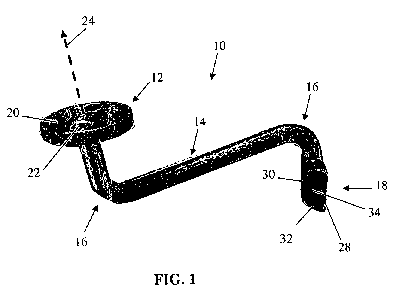
[0011] Turning now to FIG. 1, FIG. 1 is a view of an embodiment of a fiducial
base 10
according to an aspect of the invention. The fiducial base 10 includes a
marker platform 12, an
4
CA 02679369 2009-05-15
WO 2008/064126 PCT/US2007/084992
extending arm 14, turns 16, and a male base fixation member 18. The marker
platform 12 is
configured to couple a fiducial marker to the fiducial base 10. The extending
arm 14 spaces the
fiducial marker attached to the marker platform 12 away from the male base
fixation member 18
according to the number, direction, and degrees of the turns 16. The male base
fixation member
18 couples the fiducial base 10 to a bone fixation member, which then couples
the fiducial base
to a bone.
[0012] The extending arm 14 and the turns 16 may be sized according to a
desired end
position of the fiducial marker. By specifying the length of the extending arm
14 and the
placement, direction, and degrees of the turns 16, the fiducial base 10 may
position the fiducial
marker in a desired position relative to the working area of the surgery and
still within the field
of vision of the computer assisted surgical system. In an alternative
embodiment, the extending
arm 14 and turns 16 may include a continuous turn such that no part of the
extension is primarily
straight. While the extending arm 14 and the turns 16 generally extend the
reference frame and
avoid extending into the working area of the surgeon, any shape of the
extending arm 14 and
turns 16 may be used. The computer assisted surgical system may account for
different shapes
of the fiducial base 10 when the shape of the fiducial base 10 is stored
within the computer
assisted surgical system.
[0013] The marker platform 12 is configured to attach to a fiducial marker. In
one
embodiment, as shown in FIG. 1, the marker platform 12 has a circular mating
surface 20.
Recesses 22 within the circular mating surface 20 receive the fiducial marker.
The marker
platform 12 may have magnets, such as a neodymium magnet, within the recesses
22 so that the
fiducial marker may be coupled to the fiducial base 10 with positive fixation
from the force bias
created by the magnets. In addition, the fiducial marker may also include
magnets on posts
5
CA 02679369 2009-05-15
WO 2008/064126 PCT/US2007/084992
configured to couple with the recesses 22. The posts on the fiducial marker
would be oppositely
polarized from the magnets within the recesses 22. Moreover, in order to
specify a certain
orientation in the fiducial marker, magnets within the recesses 22 may be
oppositely polarized
from one another such that the fiducial marker would only achieve positive
fixation in a single
orientation of the fiducial marker with respect to the fiducial base 10.
[0014] In addition to using magnets to orient and fix the fiducial marker
relative to the
fiducial base 10, the marker platform 12 may have differently shaped recesses
22 so that the
fiducial marker may fit in a specific orientation. In another embodiment, the
mating surface 20
may have a roughened surface so that the fiducial marker is less likely to
slip relative to the
fiducial base 10.
[0015] In order for the fiducial marker to be properly viewed within the field
of view of the
surgical system and properly calculate the position of the bone to which the
fiducial base 10 is
attached, the fiducial marker may need to be rotated relative to an axis 24
perpendicular to the
marker platform 12. Any rotation of the fiducial marker around this axis 24,
as long as the
rotation is completed before registration of the fiducial marker and not
changed after registration,
may fix the relative position of the fiducial marker to the bone for accurate
computer
visualization of the anatomy. The mechanism to rotate the fiducial marker
relative to the marker
platform 12 may be positioned either at the marker platform 12 or on the
fiducial marker.
[0016] The male base fixation member 18 is configured to fix the fiducial base
10 to a
female bone fixation member (as shown in FIG. 3, and discussed below) which
attaches to a
bone. The male base fixation member 18 includes a lower mating edge 28, an
upper mating edge
30, a forward mating surface 32, a side mating surface 34, and a rear surface
portion 36. The
male base fixation member 18 is configured to slide into a recess in the
female bone fixation
6
CA 02679369 2009-05-15
WO 2008/064126 PCT/US2007/084992
member. The forward mating surface 32 is configured to mate with a forward
surface of the
female bone fixation member.
[0017] In this embodiment, the side mating surface 34 is a beveled surface
from the lower
edge 28 to the upper edge 30, and also a beveled surface from the rear surface
portion 36 to the
forward mating surface 32. The double beveled side mating surface 34 allows
for initial gross
positioning of the fiducial base 10 which transitions to fine positioning as
the male base fixation
member 18 is seated fully in the female bone fixation member. Alternatively,
other embodiments
may include a single beveled side mating surface, or a beveled side mating
surface which has a
double beveled surface from the lower edge 28 to the upper edge 30. The bevels
in the mating
surface allows for an operator to generally align the fiducial base 10 into
the female bone
fixation member. As the fiducial base 10 is advanced into the female bone
fixation member, the
beveled surfaces guide the fiducial base 10 into alignment in the base.
[0018] In one embodiment, when the male base fixation member 18 is seated, a
magnet
positively biases the male base fixation member 18 into the female bone
fixation member. The
magnet may be positioned within the male base fixation member 18 or the female
bone fixation
member, or both. The magnet(s) creates a magnetic force between the base
fixation members to
hold the base fixation members together. The force allows for small
perturbations of the fiducial
base 10 without dislodging the fiducial base 10 from the female bone fixation
member. In
addition, the small bias force also allows for a large perturbation (such as
strongly knocking the
fiducial marker, or purposely pulling on the marker) to dislodge the fiducial
base 10 from the
female bone fixation member without pulling the female bone fixation member
from the bone.
Such a system, then, creates a mechanical weak point at the fixation members
to protect the bone
from damage.
7
CA 02679369 2009-05-15
WO 2008/064126 PCT/US2007/084992
[0019] In addition to magnets, other positive bias forces may be used to
retain the male base
fixation member 18 (and thus the fiducial base 10) within the female fixation
base member.
Mechanical locking systems, which may be mechanically released, may be used to
positively
bias the male base fixation member 18 to the female bone fixation member. If
the mechanical
locking system is not releasable, then the locking mechanism may be made
weaker than the other
systems affixing the fiducial to the bone so that when the surgical procedure
is completed, the
fiducial base 10 may be removed by breaking the mechanical locking system.
Such breakable
locking systems may be single-use, disposable systems.
[0020] Turning now to FIG. 2, FIG.2 is a view of another embodiment of a
fiducial base 40
according to an aspect of the invention. The base 40 includes an extending arm
42, turns 44, a
marker platform 46, and a male base fixation member 48. The components 42-48
of the fiducial
base 40 are similar to components of the fiducial base 10 of FIG. 1. The
platform 46 is
configured to support and fix a fiducial marker to the base 40. The male base
fixation member
48 is configured to orient and fix the base 40 to the female bone fixation
member and thus fix the
base 40 to the bone. Similar to the embodiment of FIG. 1, the extending arm 42
and the turns 44
are configured to space the platform 46 from the male base fixation member 48.
[0021] The turns 44 and the extending arm 42 of the base 40 of FIG. 2 are
shaped
differently than the turns and extending arms of the base of FIG. 1. The
different lengths of the
extending arms 42, placement of turns 44, and degrees of the turns 44 orient
the platform 46
relative to the male base fixation member 48 in placement different from the
platform and the
male base fixation member of FIG. 1. Such different orientations between the
platform 46
relative to the male base fixation member 48 allow the base 40 to extend the
fiducial markers in
8
CA 02679369 2009-05-15
WO 2008/064126 PCT/US2007/084992
positions that minimally encroach the surgical area while maintaining the
fiducial markers within
the field of vision of the computer assisted surgical system.
[0022] Turning now to FIG. 3, FIG.3 is a view of an embodiment of the fiducial
base 40 of
FIG. 2 and an embodiment of a female bone fixation member 60 according to an
aspect of the
invention. The female bone fixation member 60 includes spikes 62, attachment
arms 64, and
screw recesses 66 and 70. A guide 71 of the female bone fixation member 60
includes an upper
edge 72 a lower edge 74, a forward mating surface 76 and a side mating surface
78. A bias
member 80 may be located on the forward mating surface 76. A lower surface 82
is defined by a
rear edge 84 and the lower edge 74. The side mating surface 78 is defined
vertically by the
upper edge 72 to the lower edge 74 and horizontally from each side edge 86 to
the front mating
surface 78. The side mating surface 78 is configured to mate with the beveled
surface of the
male bone fixation member 48.
[0023] The bevels in the female bone fixation member 60 are oriented to
receive the male
fixation member 48. The female bone fixation member 60 is beveled from the
rear edge 84 to
the forward mating surface 76, and is further beveled from the lower edge 74
to the upper edge
72. In addition to these compound bevels, it may be desirable to additionally
bevel the male and
female fixation members 40 and 60 with a bevel where the upper edge 72 and
lower edge 74
converge as the upper edge 72 and lower edge 74 are traced from the rear edge
84 toward the
forward mating surface 76. The bevels may allow for initial gross placement of
the male fixator
40 so that an operator may initially align the male fixator 40 with the female
fixator 60. Such a
configuration allows for an operator to be able to confidently place the
fixators 40 and 60 in
obstructed or reduced views by "feeling" for contact between the male and
female fixators 40
9
CA 02679369 2009-05-15
WO 2008/064126 PCT/US2007/084992
and 60. A generally tapered shape to the male fixator 40 allows for this
general gross placement
of the fiducial base.
[0024] M this ein6odiinent, the bias member 80 may use magnets, such as a
neodymium
magnet, within a recess in the forward mating surface 76 so that the male
fixation base member
40 may be coupled to the female bone fixation member 60 with positive fixation
from the force
bias created by the magnet. In alternate embodiments, the magnet may be
positioned within the
male base fixation member 40 or the female bone fixation member 60, or both.
The magnet(s)
creates a magnetic force between the base fixation members to hold the base
fixation members
40 and 60 together. The force allows for small perturbations of the fiducial
base without
dislodging the fiducial base from the female bone fixation member 60. In
addition, the small
bias force also allows for a large perturbation to dislodge the fiducial base
from the female bone
fixation member 60 without pulling the female bone fixation member 60 from the
bone by
ripping out the screws that attach the female bone fixation member 60 to the
bone throught he
screw holes 66 and 70. Such a system, then, creates a mechanical weak point at
the fixation
members 40 and 60 to protect the bone from damage from screw pullout.
[0025] The screw recesses 66 and 70 receive small screws to attach the female
bone fixation
member 60 to the bone. The recesses 66 and 70 may be used alternatively, or
together,
depending upon the placement of the female bone fixation member 60. The
external screw
recesses 66 may provide a lower profile for the female bone fixation member 60
because the
head of the screw used to affix the female bone fixation member 60 to the bone
does not need to
be fully seated within the guide 71 of the female bone fixation member 60. By
utilizing the
recess 70 to screw the female bone fixation member 60 to the bone, the screw
head of the
CA 02679369 2009-05-15
WO 2008/064126 PCT/US2007/084992
affixing screw must be generally flush with the lower surface 82 of the female
bone fixation
member 60 in order to receive the male base fixation member 40.
[0026] While the recesses 66 and 70 generally fix the female bone fixation
member 60 to the
bone, the spikes 62 set the female bone fixation member 60 to the bone. The
spikes 62,
generally perpendicular to the lower surface 82 of the guide 71, are first set
in the bone to orient
the female bone fixation member 60 relative to the bone. The spikes 62 are
pressed or punched
into the bone, for example, by a hammer. The spikes 62 initially orient the
female bone fixation
member 60 so that the operator may check to verify the angles of the female
bone fixation
member 60 and the male base fixation member 48 are properly aligned within the
field of view
of the tracking system prior to permanent fixation of the female bone fixation
member 60 to the
bone. Once the operator is satisfied with the initial setup with the spikes
62, then the operator
may screw the access screws through the recesses 66 and 70 to set the female
bone fixation
member 60 to the bone.
[0027] The spikes 62 and screws are generally short. The small size of the
spikes 62 and
screws allows for placement of fiducials which do not block the IM canal.
Longer spikes or
screws would extend through the bone into the IM canal, which would block the
IM canal and
interfere with placement of additional alignment devices through the IM canal,
such as the
alignment devices commonly used in total knee replacement surgeries. The
smaller spikes 62
and the screws may not need to be as deep into the bone as the screws because
the geometry and
characteristics of the base 40 allow for lower transmitted forces and moments
to the fixation
member 60.
[0028] Turning now to FIG. 4, FIG. 4 is a view of a pair of fixation members
90 and 92
coupled to a femur 94 and a tibia 96. Fixation member 90, may be attached to
the femur 94
11
CA 02679369 2009-05-15
WO 2008/064126 PCT/US2007/084992
proximal to the medial epicondyle 98 and posterior to the adductor tubercle
100. Such a
placement would allow the femoral fixation member 90 to be fixed to the bone
through the
primary incision for the surgical procedure, for example a total knee
replacement. The fixation
member 92 may be placed distal, medial and posterior to the tibial tuberosity
102. Similarly, this
placement also allows the tibial fixation member 92 to be inserted through the
primary incision.
[0029] Both the femoral fixation member 90 and the tibial fixation member 92
are placed to
minimize operator interference, particularly from interfering with a surgeon.
By placing the
fixation members 90 and 92 medial to the center of the joint, the surgeon or
other technicians
may not cross over the fiducials in order to access the joint. Moreover, the
placement of the
femoral fixation member 90 proximal to the joint working surfaces and the
placement of the
tibial fixation member 92 inferior to the joint working surfaces also
minimizes interference
between the fiducials and a surgeon.
[0030] The base fixation members 90 and 92 are oriented to project the
fiducial bases
toward the joint. Such an orientation minimizes the need to increase the
incision size by
allowing for the fiducial bases to project toward the joint while at the same
time projecting
anterior to the joint to move the bases away from the working area of the
joint. The base
fixation members 90 and 92 may be oriented to project the fiducial bases close
to the ends of the
incision, or may be oriented more toward the middle of the incision.
[0031] The base fixation members 90 and 92 are initially set in the bone with
spikes 104 and
106. The spikes 104 and 106 are spaced differently than the spikes from the
fixation member of
FIG. 3. The spikes 104 and 106 are spaced from the front to the back of the
base fixation
members 90 and 92, while the spikes of FIG. 3 are placed laterally from side
to side. Other
12
CA 02679369 2009-05-15
WO 2008/064126 PCT/US2007/084992
embodiments, including spacing the spikes both from side to side and from
front to back may be
utilized according to the position of fixation and user preference.
[0032] The femoral fixation member 90 is fixed to the bone using screw
recesses 108
through attachment arms 110. The attachment arms 110 may be located on the
sides or on either
the front end or the rear end of the fixation member 90. The arms 110 may be
offset from one
another along the length of the sides or the ends, or may be positioned one on
a side and one on
an end. While this embodiment has shown a pair of attachment arms 110, it may
be beneficial to
use a single attachment arm or more than two attachment arms according to the
anatomy of the
placement or the preference of the surgeon. Using a single attachment arm, the
spikes 104 may
help fix the fixation member 90 to the bone without rotation of the fixation
member 90 about the
screw recess 108.
[0033] The tibial fixation member 92 is configured with an open front end 114.
The forward
movement of the base into the fixation member 92 is controlled by beveled side
surfaces 116 of
the fixation member 92. While both sides of the fixation device 92 are
beveled, it may be
possible to have only a single side of the fixation member 92 beveled. In
addition, the tibial
fixation member 92 further includes a single center screw hole 118 to affix
the fixation member
112 to the bone. The additional thickness of the fixation member 92 compared
to the thickness
of the fixation member 90 may be attributed to the center screw hole 118 which
may flush the
screw relative to the fixation member 92.
[0034] While the different fixation members 90 and 92 of FIG. 4 and the
fixation member
60 of FIG. 3 have different features and alternative means for achieving
different functions, the
different features and alternates may be mixed and modified across different
fixation members
both as shown in the drawings and as discussed above. For example, an open-
ended fixation
13
CA 02679369 2009-05-15
WO 2008/064126 PCT/US2007/084992
member like fixation member 92 may have a pair of attachment arms like the
fixation member
90, where the attachment arms are offset along the side walls of the fixation
member.
[0035] Other fixation members may also be configured with male mating
portions. In such
an embodiment, the fiducial base may be configured having a female mating
portion. Such a
configuration may allow for the bone fixation member to have a low profile for
improved ease of
implantation when the bone fixation member is affixed to the bone. In
addition, a male bone
fixation member may have beveled edges as previously described. Generally, the
mating
portions of the bone fixation member and the fiducial base are negatives of
each other, such that
the negative spaces of the female mating portion is shaped like the male
mating portion, and vice
versa.
[0036] Turning now to FIG. 5, FIG. 5 is a view of the fiducial bases 10 and 40
of FIGs. 1
and 2 coupled to the bone fixation members 90 and 92 of FIG. 4. The fiducial
base 10, attached
to the tibial bone fixation member 92, extends toward the inferior portion of
the knee joint,
where the inferior portion of an incision would be located. The fiducial base
40 attached to the
femoral bone fixation member 90 extends toward the knee joint from the
superior location of the
femoral bone fixation member 90 where the superior portion of a skin incision
would be located.
[0037] The orientation of the bases 10 and 40 and bone fixation members 90 and
92 ease
access to the joint while keeping the fiducials in the field of view. The
bases 10 and 40 extend
anterior to the knee joint, which may allow the bases 10 and 40 and the
markers connected to the
bases 10 and 40 to be elevated away from the working area around the knee
joint. In addition, in
this embodiment, the planes of the surfaces of the platforms 12 and 46 of the
bases 10 and 40 are
not parallel when the knee joint is fully extended. However, as the knee is
flexed, the planes of
the surfaces of the platforms 12 and 46 of the bases 10 and 40 rotate into
more parallel
14
CA 02679369 2009-05-15
WO 2008/064126 PCT/US2007/084992
orientations. This may allow fiducials, extending perpendicular to the planes
of the surfaces of
the platforms 12 and 46 to also be parallel and jointly viewable within the
field of view of the
computer assisted surgical system. Moreover, the projections of the bases 10
and 40 may
minimize loss of data caused by obstruction between the sensing system and the
fiducials from
either an operator or the patient by elevating the fiducials away from the
working area of the
joint. Other embodiments which plan for the relative placement of the
fiducials with respect to
the sensing system of the computer assisted surgical system may use
differently oriented bone
fixation members 90 and 92, or differently shaped bases 10 or 40 according to
the field of view
of the computer assisted surgical system.
[0038] Turning now to FIG. 6, FIG. 6 is a cross sectional view of an
embodiment of a
fiducial base 128 coupled to a bone 130 according to an aspect of the
invention. A bone fixation
member 132 is set into the bone 130 using spikes 136. The fiducial base 128 is
inserted into the
bone fixation member 132 and extends toward an incision 142 in soft tissue
144, including skin
and muscle. The bone fixation member 132, then, is located between the soft
tissue 144 and the
bone 130. The soft tissue 144 may also add a slight pressure to the bone
fixation member 132 to
fix the bone fixation member 132 to the bone 130.
[0039] When the bone fixation member 132 and the base 128 are installed, the
surgeon
begins by first making the incision necessary for the surgery. Thus, the
installation of the bone
fixation member 132 may not require a longer incision. The soft tissue 144 is
pulled back to
expose as much of the bone 130 as possible. The surgeon may slide the bone
fixation member
132 under the soft tissue 144. The bone fixation member 132 may be attached to
the bone 130
with a small mallet or other device used to impart a direct force to the bone
fixation member 132,
driving the spikes 136 into the bone. The surgeon may then check the
orientation of the bone
CA 02679369 2009-05-15
WO 2008/064126 PCT/US2007/084992
fixation member 132 by inserting the base 128 into the bone fixation member
132. If the
orientation is correct, then the surgeon may use the small screws to attach
the bone fixation
device 132 to the bone 130. If the orientation is not correct, then the
surgeon may reset the bone
fixation member 132, or may try additional bases that are shaped differently.
Once the bone
fixation device 132 is properly oriented and fixed to the bone 130, then the
fiducial base 128 is
set in the bone fixation member 132.
[0040] When the bone fixation member 132 is fixed under the soft tissue 144 to
the bone
130, the bone fixation member 132 may be accessed "blind." It may not be
necessary for the
surgeon to see the bone fixation member 132 when inserting the base 128 into
the bone fixation
member 132. The beveled surfaces of the bone fixation member 132 and the base
128 allow for
a surgeon to first insert the smaller male mating portion of the base 128 into
the largest female
mating portion bone fixation member 132. Thus, the base 128 is guided into the
bone fixation
member 132 by feel.
[0041] Turning now to FIG. 7, FIG. 7 is a view of an embodiment of a fiducial
base 150
and bone fixation member 152 coupling a fiducial marker 160 to a bone 162
according to an
aspect of the invention. The fiducial marker 160 is extended above the joint
and medial to the
joint so that a surgeon operating from the lateral side of the joint is less
likely to come into
contact with the fiducial marker 160 or any of the other parts of the system.
[0042] The bone fixation member 152, as previously stated above, may be
designed for
fixating to the bone in an obstructed view. The bevels in the mating surfaces
of the bone fixation
member 152 allows for gross placement of the fiducial base 150 into the bone
fixation member
152, which when further slid along the mating surfaces, fixes the fiducial
base 150 into the bone
fixation member 152. In addition, the bone fixation member 152 allows for
fixation of the
16
CA 02679369 2009-05-15
WO 2008/064126 PCT/US2007/084992
fiducial marker 160 without invading the IM canal without using long screws to
fix the fiducial
marker 160 to the bone 162.
[0043] The fiducial base 150 is configured to position the fiducial marker 160
away from the
bone 162. The fiducial base 150 may use a combination of turns and extensions
to extend the
fiducial marker 160 away from the bone 162 through the primary incision, and
elevated from the
working area of the surgery. Depending on the number of turns, degree of the
turns, and length
and placement of the extensions, varying geometries may be achieved to
position the fiducial
marker 16 away from the surgical approach.
[0044] The bone fixation member 152 is positioned to minimally interfere with
the surgical
approach. This requires placement of the bone fixation member 152 away from
the surgical
incisions. The bone fixation member 152, then, is isolated from interfering
with tools in surgery.
For example, a more centrally placed fiducial may use long screws to attach
the fiducial to the
bone. In such a system, bone cuts and guide placement may be affected by the
long screws, or
even the fiducial itself. When the bone fixation member 152 is attached to the
bone 162, its low
profile and gross guides may allow for positioning farther from the surgical
approaches.
Moreover, the structure of the fiducial base 150 extending through the
incision farther from the
more centralized portions of the surgical approach may minimize obstructions
caused by the
fiducial marker during surgery.
[0045] In addition, the connections between the fiducial base 150 and either
the bone
fixation member 152 or the fiducial marker 160 may be detachable. A detachable
connection
may allow for small perturbations of the fiducial marker 160 or the fiducial
base 150 without
dislodging the bone fixation member 152 from the bone 162 or adjusting the
bone fixation
member 152 relative to the bone 162. When the marker 160 is disturbed, the
connections may
17
CA 02679369 2009-05-15
WO 2008/064126 PCT/US2007/084992
detach, which would then require an operator to reconnect the detached
connection. For
example, a slight perturbation may dislodge the marker 160 from the fiducial
base 150. Minimal
forces would be transferred to the bone fixation member 150, and thus preserve
the bone fixation
member 152 to bone 162 connection.
[0046] The devices 150-160 may be fabricated from rigid biocompatible
material. The
material may be worked using standard CNC machining processes, or by other
manufacturing
processes. Magnets, placed in the connections between the devices 150-160, may
be made from
rare earth metal materials such as neodymium. Sensors in the fiducial markers
160 may be made
from a material detectable in the field of view of the computer assisted
surgical system, and
preferentially, the material for the sensors should be different from the
material which makes the
fiducial base 150 the bone fixation member 152 and the frame portion of the
fiducial marker 160
so that the sensors are primarily viewable by a sensor within the computer
assisted surgical
system.
[0047] Turning now to FIG. 8, FIG. 8 is a schematic view of a computer
assisted surgical
system 200 according to an aspect of the invention. The computer assisted
surgical system 200
uses a fiducial marker 202 to obtain the position and orientation of a bone
204 when the marker
202 is distanced from the bone 204 using a fiducial base 206 and a bone
fixation member 208. A
tracking sensor 210 images the marker 202 such that a representation of the
bone 204 may be
displayed on a monitor 212. Other fiducial markers 202 may be placed on
instruments 216 so
that these devices may also be displayed on the monitor 212. An imager 218 may
be used to
correlate the information from the markers 202. A foot peda1220, controlled by
an operator such
as the surgeon may also be used in the computer assisted surgical system 200
for input. Input
from the tracking sensor 210, the imager 218 and the foot pedal 220 may be
input into a
18
CA 02679369 2009-05-15
WO 2008/064126 PCT/US2007/084992
computer interface 222 for collection and processing to output to the monitor
212. The computer
interface 222 may include memory 224, a processor 226 and an input/output
interface 228. The
i/o interface 228 may also be connected to a network 230, for transmission
over a network to
other individuals or other storage mediums.
[0048] When the system is initiated, the marker 202 is registered at a first
position of the
bone 204. As the bone 204 is moved, the marker 202 is moved and rotated in
three dimensions
relative to the first position. By using additional markers attached to the
bone 204, the computer
interface 222 may calculate positions of the bone 204, because the marker 202
does not move or
rotate relative to the bone 204. Additionally, the computer interface 222 may
also register
instruments 216 within the field of the tracking sensor 210 so that instrument
movement may
also be tracked.
[0049] As various modifications could be made to the exemplary embodiments, as
described
above with reference to the corresponding illustrations, without departing
from the scope of the
invention, it is intended that all matter contained in the foregoing
description and shown in the
accompanying drawings shall be interpreted as illustrative rather than
limiting. Thus, the breadth
and scope of the present invention should not be limited by any of the above-
described
exemplary embodiments, but should be defined only in accordance with the
following claims
appended hereto and their equivalents.
19