Note: Descriptions are shown in the official language in which they were submitted.
CA 02679717 2009-04-06
PCT/CA2007/001835
20 May 2008 20-05-2008
H-876-0-WO
APPARATLTS AND METHODS FOR ACTIVE MOLD DECOMPRESSION &
MELT ACCUMULATION IN A SHOOTING POT RESERVOIR
OF AN INJECTION MOLDING MACHINE
TECHNICAL FIELD
This invention relates, in general, to the operation and configuration of a
two-stage injection
molding machine and is particularly, but not exclusively, applicable to a melt
accumulation stage
(involving collaboration between an injection piston and plunger in an
injection cylinder) of an in-
line compounding machine that operates to produce a shot of plastic melt
containing glass fibre (or
similar) additives.
BACKGROUND OF THE INVENTION,
1s Injection molding technology supports the production of molded parts of
varying sizes, e.g. bottle
preforms; car bumpers and component housings. The benefits of injection
molding technology
include cycle speed, consistently reproducible part quality and cost.
Especially in the context of
plastic injection molding, parts are relatively light when compared with cast.
steel or machined metal
alternatives.
In relation to large-sized lightweight molded parts or parts that require high
residual strength,
injection molding platforms are moving towards technologies such as:
i) Thixomolding in which molten magnesium is injected under very low pressure,
but at very
high speed, to form an injection molded metal part. Processing of molten
niagnesium is somewhat
abrasive on the system components, especially the extruder unit, and it is
also necessary for. the
mold to be treated with release agents to facilitate part de-molding; these
are two obvious
drawbacks.
ii) Water Injection Technology (WiT) that operates to produce hollow plastic
components. In
this technology, shortly after injection and prior to plastic solidification,
the molten core of the
plastic part is ejected from the part into a collection reservoir using a
stream of high pressure water.
Depending on part shape, this technology can unfortunately produce non-uniform
wall thicknesses
in the finished article, since the flow and action of pressurized water cannot
be deterministically
controlled. Some of the physical bulk of the molded part is thus removed, but
this also potentially
reduces the inherent physical strength of the molded part.
. iii) Gas-assisted injection technologv employs a similar concept to WIT,
albeit that the phase
of the evacuating component is different.
e.m~mTar. ocfos+m . ,
CA 02679717 2009-04-06
_._.-_ ..__..... _- . __.. . ..__.-_ . _. __ __-------- __..._ ...-- --= ..-
.._ _ _-=-- .. . --=----..__... . .._ ...___.__ _
PCT/CA2007/001835
20 May 2008 20-05-2008
H-876-0-WO
iv) In-line compounding (particularly in the sense of two-stage injection
units).
Single stage, reciprocating screw (RS) plasticizing units have, in the past,
been used to process: i),
"pultruded pellets"; and ii) pre-compounded fibres set into a therenoplastic
resin pellet. In an RS
extruder, the reciprocating screw is drawn or forced backwards along the
barrel during the
plasticizing cycle to permit melt to be accumulated.in front of a tip of the
screw. Pultruded pellets
. .
contain strands of fibres that are initially about -10 millimetres (mm) to -
12mm in length, whereas
the pre-compounded fibres are significantly shorter (typically -lmm to -2mm).
The inevitable
shearing action of the RS extruder leads to a significant shortening of these
fibres to the extent that a
finally molded part includes fibres that are typically less than about -3mm.
to 5mm in length (from
the pultruded pellets) and generally less than -lmm (for pre-compounded
fibres). Additionally, the
_
abrasive nature of these fibres causes barrel wear issues which must be
addressed either through
regular maintenance of the machine or the provisioning of appropriate barrel
liners and/or screw
geometries.
In-line compounding is a two-stage technology that generally commences with a
spooled line. of
fibres, typically glass-fibres (or the like), that are drawn into a two-stage
extruder unit by the (usual
use and) operation of a twin-screw extruder (TSE). Within the barrel, the
flights and configuration
of the TSE initially operate to cut each line of fibres into short lengths in
the range of about 15mm
to 50mm, with the process of melt passage (in the extruder and the associated
channelling to the
mold) then further reducing the length of these already shortened fibres
through the actions of shear
forces. In general, in glass-fibre type compounding, it will be understood
that a certain length of the
TSE is used. to compound the glass-fibre into the polymer matrix, and that the
screws include
typically two sets of cutting elements, namely one near a feed-throat for the
glass-fibre and one
close to a tip of the extruder. Pre-chopped fibres could, however, be used to
. replace. the
requirements of a spool-fed line. In in-line compounding, the objective is a
final average fibre
length of at least -10mm, although the longer the better.
Twin screw extruder technology is favoured, but not essential, to in-line
compounding because it
generally and advantageously provides a less harsh treatment of the chopped
fibres. Beneficially, the
kneading actions of TSEs ensure that the melt is homogenized and that
particles (e.g. fibres or other
additives) are evenly.distributed.
In both the RS and TSE environinents, from a perspective of an overall machine
configuration and
operation of an in-line compounding machine, it will be understood that,
following production of a
homogenized plastic melt by the extruder (irrespective of whether the process
is continuous or
2
CA 02679717 2009-04-06
PCT/CA2007/001835
20 May 2008 20-05-2008
x-s76-0-WO
discontinuous), plastic melt is injected into a mold that is clamped between a
stationary platen and a
moving platen. The mold is, in fact; usually accessed via a suitable
distribution manifold (such as a
hot runner) that is coupled to.the injection unit through a series connection
of sprue bushing (that
interfaces between. the distribution manifold) and a tip of a nozzle adaptor
that provide a flow
s passage for a melt collection chamber, e.g. the shooting pot.
More particularly, in a two-stage environment, a barrel head of the TSE is
coupled to a distributor
valve via a melt transfer channel (in the form of a generally straight pipe
between the extruder barrel
head and, typically, a two-way valve). More specifically, with a two-way valve
configuration,
plastic melt (under pressure flow conditions) flows through the transfer
channel (from the TSE) into
a shooting pot that accumulates a shot of plastic for subsequent.injection
into the mold during a
molding- cycle. As homogenized melt is accumulated, a piston of the shooting
pot is controllably
rnoved backwards to increase the volume of the shooting pot, thus allowing the
shooting pot to store
more melt over time. Once a full shot of plastic has been accumulated in the
shooting pot, the two-
way valve is re-configured t.o couple the shooting pot to the manifold through
the nozzle adaptor
that conventionally interfaces to a sprue on the manifold. An injection piston
is then forced forward
to engage the plunger to eject melt out of the nozzle. Once the injection
stroke is completed, the
injection piston is withdrawn. The injection piston is therefore not connected
to the plunger.
Consequently, the TSE generally operates in a discontinuous mode (where
plasticizing operation is
periodically restricted) since the TSE is periodically isolated from any form
of collection vessel and
continuous plasticization would present logistical storage problems for the
system, since the screws
in a TSE do not reciprocate to create a reservoir downstream of them in the
barrel.
In a two-stage. system, finally, to effect injection of melt under high
pressures into the mold, the
machine platens and the mold are clamped together under applied tonnage and
then the injection
piston is forced forward to empty the shooting pot.
In overview, in a compounding system, to ensure molded part strength, besides
having.to ensure that
the fibres are evenly distributed throughout the plastic melt and hence within
the fiiial molded part,
it is important that the fibres remain relatively long (since this
intrinsically provides bonding
strength). Equally, it is desirable that there is a narrow glass fibre length
distribution from an
average fibre length; this provides uniformity in the bulk properties of the
molded part.
In any two-stage system, one of the problems that must be addressed. relates
to possible drooling of
melt at the non-accessible/non-visible interfaee between the hot and cold
regions of the mold. This
3.
CA 02679717 2009-04-06
PCT/CA2007/001835
20 May 2008 20-05-2006
H-876-0-WO
interface is generally known as the "sprue" and is found at the tip of a
nozzle adaptor (which is itself
located in front of the shooting pot and plunger assembly). Unfortunately,
drooling can result in
solidifica.tion of the plastic and this can cause both future contamination of
an injection shot and/or
a complete blockage or a flow restriction within the melt path from the
shooting pot to the mold. In
relation to any form of flow restriction (whether complete or partial), the
system is therefore
susceptible to different fill profiles between successful cycles; this is
unacceptable. Any change in
the flow fill profile can also result in undesirable weld lines oceurring at
uncontrollable positions
within the molded part. These weld lines are reflective of areas on non-
homogeneity and,
consequently, cause the molded part to experience different, uncontrolled and
undesirable
to mechanical properties at different locations within its struc,ture..
In packaging environments, the plunger and injection unit are permanently
coupled together. As
melt is fed into the shooting pot, a coordinated, slow backwards movement of
the plunger and the
injection unit keeps -the head of the plunger in close proximity to the melt
front, although the melt
front often exerts a positive force to also assist in pushing the plunger
backwards. This slow,
backwards movement may have a limi#ed decompression effect on the hot runner.
At a given point,
this mechanically-assisted movement is stopped, thereby causing the melt to
undertake all the work
required to push back completely the piston-plunger assembly and thereby to
pack out the shooting
pot to eliminate spaces and air pockets within the accumulated melt.
In certain and current PET injection molding systems, the injection piston and
plunger are
mechanically isolated from one another. Specifically, during shot
collection/accumulation, the
injection piston is hydraulically withdrawn to the shot volume minus a small
packing distance,
whereas the injection plunger is singularly driven. back to the requisite shot
volume minus the small
-25 packing distance by the sole action of the melt. In this way, when
extruded melt is.communicated
througb the transfer channel (via a two-way valve and into the shooting pot)
the melt transfer
pressure and therefore melt load is minimized. In other words, the melt does
not have to. undertake
"work" in pushing back the injection piston over the majority of its.distance,
but it does undertake
work in relation to the plunger over the entire distance that the pluriger
travels. The melt does
therefore experience shear and, consequently, fibre length (for in-line
compounding applications)
can be maintained to some extent during this initial phase of melt
accumulations. [As will be
understood, shear effects have the results of both reducing fibre' length (in-
line compounding
appliaations) andaflecting general melt properties/quality]. Eventually,.melt
causes the plunger to
contact the injection piston and both are then forced backwards together over
a sma1l distance to
ensure that the futal accumulated shot contains no air/spaces. During this
time when there is the
final take-up (typically over the last few millimetres of travel of the
plunger) significant work is
4
CA 02679717 2009-04-06
PCT/CA2007/OO1835
20 May 2008 20-05-2006
H-876-0-WO
done against: i) hydraulic oil pressures associated with the injection piston;
ii) the frictional forces
related to movement of the injection piston that is now contacted by the
plunger; and iii) the mass of
(particularly) the injection piston.
s US patent 6,241,932 describes the conventional separation of the melt
preparation and the injection
system in which the plunger is not connected to the injection piston. In this
patent, after the.hold
period, the injection piston is pulled back to the requisite shot size and
extruded melt pushes the
plunger backwards. A sensor is used to measure the instant when the plunger
contacts the injection
piston. Generally, this configuration is used in a PET (multi-cavity)
injection molding environment'
where valve-gating technology is used to shut off and open up the cavities.
Unfortunately, while valve gating can provide an effective shut off (anti-
drool) capability, valve
gate technology cannot be applied to an in-line compounding environment where
long fibres can
potentially became entwined or otherwise wrapped around the valve stem,
whereafter operation of
the valve stem is restricted or stopped.
For in-line compounding, one apparent solution proposed by the company Krauss-
Maffei
Kunststofftechnik GmbH of Munich, Germany, is to include a pressure transduoer
in front of the
extruder unit (i.e. in the transfer channel between the extruder and the
nozzle adaptor): This system
has the. plunger permanently coupled to the injection unit. The pressure
transducer acts to measure
pressure and, based on a pressure signal, actively controls the backwards
movement of the
combined piston and plunger sub-assembly. Consequently, the signal processing
and control is
relatively complex and expensive and the melt always experiences some pressure
as it abuts against
and pushes the plunger (notwithstanding that the plunger's movement is
assisted). This
configuration therefore sees that melt continues to perform work in moving the
combined mass of
the plunger and injection piston and also in overcoming fractional and
resistive forces associated
with these system components and their function. In any event, the location of
the transducer in the
transfer channel is not ideal and its pressure measurement therefore relates
to the extrusion pressure
and not the pressure in the shooting pot reservoir. T,ocation of the pressure
transducer in the barrel is
possible, but not considered particularly viable.
For completeness, it is noted that certain systems already include a pressure
transducer downstream
i. .
of the extruder and typically within the transfer channel between the extruder
and the two-way valve
26. Persons skilled in the art will appreciate that the two-way valve 26 is a
diagrammatic
representation of a two-way value 26 and the representation does not
illustrate the inteznal structure
or mechanics of the two-way valve. Persons skilled in the art will also
appreciate that the two-way
5
CA 02679717 2009-04-06
PCT/CA2007/001835
20 May 2009 20-05-2008
H-876-0-WO
valve operates to permit a transfer of melt from the transfer channel 30 to
the shooting pot reservoir
28, or a transfer of melt from the shooting pot reservoir 28 to the hot runner
20. Sueh pressure
transducers, however, generally act as safety devices and are linked to an
extruder controller that
operates to shut down the extruder whenever excess pressure is measured (for
whatever reason).
The transducer therefore acts to prevent the bearings in the extruder from
being overloaded and thus
' to restrict the likelihood of potentially expensive damage being done to the
extruder.
EP-B-0538286 (Putsch) describes an in-line compounding system that operates in
a continuous
fashion. Homogenized melt is buffered in a temperature-controlled buffer store
before being
introduced into an. injection plunger unit. EP-B-0538286 further discusses the
use of differing types
of additives and fibres to produce a variety of plastic parts having different
properties and uses.
SUMMARY OF THE UWENnON
According to the invention there is provided a method of active decompression
of an injection
molding system having a molding environment containing at least one of a mold
and a runner
system the injection molding system having a combination of an injection
plunger and an injection
piston arranged to effect injection of melt into the molding environment, the
method comprising:
temporarily coupling the injection plunger to the injection piston to effect
limited decompression of
the molding environment, the temporary coupling permitting the injection
plunger and injection
piston to be pulled back together at a time after the injection of inelt; and
at a time after the injection
plunger and injection piston have been pulled back together, physically
separating the injection
piston from the injection plunger to permit the injection piston to be pulled
away from the injection
plunger in an assisted manner.
In another aspect of the present invention there is provided a method. of.
developing volume in a
shooting pot reservoir in an injection cylinder containing a moveable plunger
and an injection
piston, the method comprising: initially connecting together and pulling back
the plunger and the {
injection piston to define a first volume within the shooting pot reservoir,
disconnecting the plungec
from the injection piston and pulling back the injection piston to a
predefined check point; and
accumulating melt in the first volume and permitting the plunger to be pushed
back by action of the
melt, the volume of the shooting pot reservoir thereby increasing as the
plunger moves towards the
injection piston at the predefined check point.
In a further aspect of the present invention there is provided a two-stage
injection unit having: a
shooting pot for accumulatirig, in use, a shot of melt; a plunger axially
movable vvithin the shooting
6
CA 02679717 2009-04-06
pCT/CA2007/001835
20 May 2008 20-05-2008
H-876-0-WO
pot; an injection piston arranged to initiate, in use, ejection of the shot of
melt accumulated in front
of the plunger and within the shooting pot; a drive unit, coupled to the
injection piston, for both
driving the injection piston fonvard to force, in use, ejection of melt from
the shooting pot and for
retracting the injection piston backwards; and a coupling permanently attached
to one of the plunger
and the injection piston, the mechanical coupling selectively connectable to
the other of the plunger
and the injection piston to permit: i) the plunger and the injection piston to
be connected together
temporarily during a portion of the melt accumulation process; and ii) the
injection piston and the
plunger to be retracted together by the drive unit for a first period of time
after the ejection of inelt.
from 'the shooting pot and for the injection piston to be retracted
independently of the plunger
during a second of period of time that follows the first period of time.
In one embodiment, a first sensor is arranged to generate a first control
signal that temporarily
suspends retraction of the injection piston at the end of a decompression
stroke. The fnst control
signal may also cause the coupling to effect disengagement of the plunger from
the injection piston.
In yet another aspect of the present invention there is provided an injection
molding machine
comprising a two-stage injection unit: a shooting pot for accumulating, in
use, a shot of melt; a
plunger axially movable within the shooting pot; an 'injection piston arranged
to initiate, in use,
ejection of the shot of inelt accumulated in front of the plunger and within
the shooting pot; a drive
unit, coupled to .the injection piston, for both driving the injection piston
forward to force, in use,
ejection of melt from the shooting pot and for retracting the injection piston
backwards; and a
coupling. permanently attached to one of the plunger and the injection piston,
the mechanical coupling seleotively connectable to-the other of the plunger
and the injection piston to permit: i) the
plunger and the injection piston to be connected together temporarily during a
portion *of the melt
accumulation process; and ii) the injection piston and the plunger to be
retracted together by the
drive unit for a first period of time after the ejection of melt from the
shooting pot and for the
injection piston to be retracted independently of the plunger during a second
of period of time that
follows the first period of time.
In one embodiment, the injection unit molding machine is an in-line
compounding machine that
uses glass fibres or the like within a polymer matrix.
Advantageously, the present invention provides a simplified de-compression
system that reduces the
likelihood of drool from a cavity or nuiner systems while furthermore reducing
-shear stresses
experienced within a melt during accumulation in a shooting pot. The system is
operator friendly in
that it is easy to set up and requires only knowledge of the final shot
size/volume to be injected and
7
CA 02679717 2009-04-06
PCT/CA2007/001835
20 May 2008 20-05-2008
H-876-0-WO
hence the end point of travel of the injection piston. Use of a simple
position switch or timing
calculation may act as a trigger for coupling and decoupling. Beneficially,
the present invention
does not require detailed signal processingy nor multiple measurements of
pressure or plunger
location.
BRIEF DESCRIPTION OF THE DRAWINGS
Embodiments of the present invention will be described, by way of example
only, with reference to
the drawings in which:
FIG. 1 is a schematic representation of a typical injection molding machine
that can be
adapted to include the present invention;
FIG. 2 is a sectional view through an injection unit of a preferred embodiment
of the present
inventiori;
FIG. 3 is a preferred embodiment of a selectively operational connection
between a plunger
and an injection piston ofFIG. 2;
FIG. 4 is ari alternative embodiment of a selectively operational connection
between a
plunger and an injection piston of FIG. 2;
FIG. 5 is a schematic representation of various and successive stages of
accumulating and
injecting melt employed by the injection unit of FIG. 2; and
FIG. 6 is a timing diagram of an injection cycle that reflects the process of
FIG. 5.
DETAILED DESCRIP'.CION OF THE PREFERRED EMBODIMENT(S)
FIG. 1 shows a typical injection molding machine 10 (although in this case an
in-line compounding
machine) that can be adapted to support an active decompression function
according to the various
embodiments of the present invention. Although represented as a two-platen
system, the machine
could equally be a three platen machine (for example).
Like conventional machines, during each injection cycle, the molding machine
10 produces a
number of plastic parts corresponding to a mold cavity or cavities defmed by
complementary mold
halves 12, 14 located within the machine 10.
The injection-molding machine 10 includes, without specific limitation, a
clamp unit 16 as well as
an injection unit 18 for plasticizing and injecting material. In operation,
the movable platen is.
moved relative to the fixed platen by means of stroke cylinders or the like.
Clamp force is developed
in the machine, as will readily be appreciated, through the use of tie bars
and a tie-bar clamping
8
CA 02679717 2009-04-06
PCT/CA2007/001835
20 May 2008 20-05-2008
x-s76-0-WO
mechanism. The clamping mechanism -is (generally) fixedly attached to the
moving platen (typically
through the use of bolts): Once the tie-bar is positively engaged in its
respective clamp piston, mold
clamp force (i.e. closure tonnage) can be applied through the use of
(typically) a hydraulic system
that is usually directly associated with the clamp piston.
The mold halves 12, 14 together constitute a mold generally having one or more
mold cavities, with
the mold halves 12, 14 each located in one of the movable platen and the fixed
platen. The mold
halves will, as usual, include projections (such as mold cores or leader pin
alignment columns) that
must be aligned and interconnected accurately to avoid wear and to produce
commercially
acceptable parts.
In terms of the injection unit 18, this typically interfaces to some form of
distributor 20 at the back
of a hot half of the mold. The distributor could be a hot runner or a cold
runner, for example. A
sprue 22 provides an interface between the distributor 20 and a nozzle adaptor
24 that houses a two-
way valve 26. The two-way valve 26 permits either: i) the sprue 22 to be in
fluid communication
with a shooting pot reservoir 28; or ii) a transfer channel 30 (connected to
an extruder 32) to be in
fluid communication with.the shooting pot reservoir 28. The injection unit 18
fnrther includes an
injection cylinder 33 that includes an injection piston 34 that is axially
movable by (typically) a
hydraulic drive 36. The injection cylinder 33 further includes an injection
plunger 38 is axially
movable within the injection cylinder, with the plunger 38 helping to define
the shooting pot
reservoir 28 where melt can accumulate.
The extruder 32 contains a plasticizing screw 40 within a barrel 41, the
barrel having at least one
material entry point, e.g'. feed-throat 42, receptive to gravitational dosing
of a matrix material, such
as plastic pellets from hopper/dryer 44. In the case of an in-line compounding
machine, the barrel 41
also includes a rovings entry point 46 into which are fed glass fibres or the
like for compounding
requirements. As appropriate, the barrel 41 may also include a vacuum port 50.
The plasticizing screw 40 is driven by a suitable motor 52 coupled through a
gearbox 54.
Operational control of the system is conventionally performed via a machine
controller 60 that it
includes a human-machine interface (FIlVII) 64 permitting entry and display of
data. Aznongst other
operations, the machine controller 62 controls the operation of the clamp unit
16, the injection unit
18 (including the.injection piston 34 and plunger 38) and the extruder 32.
These operations may be
triggered, controlled or regulated by control signals generated by suitably
Ioca.ted sensors within the
system. Closed loop control architecture is sometimes used.
9
CA 02679717 2009-04-06
PCT/CA2007/001835
20 May 2008 20-05-2008
H-876-0-WO
= ,
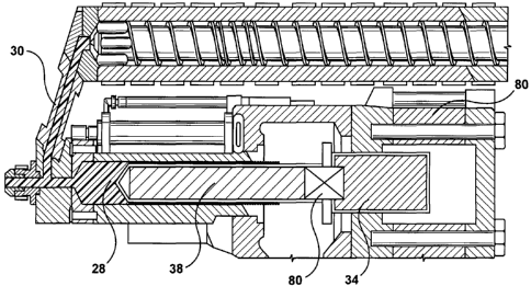
Referring briefly to FIG. 2, a section view through an injection unit of a
preferred embodiment of
the present invention is shown. In addition to the basic component
configuration of FIG.1, FIG. 2
includes a connector (i.e. a coupling) 80 that is preferably, but not
necessarily, located between an
end of the plunger 38 (remote from the barrel head/two-way valve 26) and the
injection piston 34.
The connector 80 permits selective coupling of the plunger 38 to the injection
piston 34. The exact
position and location of this connector is not important, although it must be
permanently coupled toa
at least one of the plunger 38 or the injection piston 34. The exact point of
fixing is also not
important, but presently the end of one of these units is easily accessible
and therefore the most
logical and practical choice.
. - . '
Referring to FIGs. 3 and 4, two altemative embodiments for the connector 80
are shown.
In a first embodiment (FIG. 3), the connector is realised by an electromagnet
82 that is permanently
coupled (e.g. through the use of bolts 84) to the end of the injection piston
34. Provided that the
plunger 38 is made of a magnetic material (usually steel), selective
energization of the
electromagnet 82 permits the injection piston 34 to be coupled to the plunger
38. Control of the
electromagnet 82 is rested with the machine controller 60. For the sake of
simplicity and clarity, the
various electrical connections to the electromagnet have been omitted,
especially since the wiring of
such a circuit is well known and understood by the skilled addressee.
Optionally, the electromagnet
may be recessed into one of the injection piston 34 or the plunger 38, with
accurate recessing
providing stability for the electromagnet's overall installation.
In the alternative (FIGA), rather than in using an electromagnet 82, an
alternative embodiment for
the connector 80 uses an engagement actuator 85. The engagement actuator 85,
which may be
driven hydraulically or electrically (e.g. by a piston assembly located in a
surface of the injection
piston 34 or a servo motor, respectively) includes a pin or shutter 86 that is
extended or rotated by
the actuator 85 to engage within a complementary latch or channel 88 in a
surface 90 of the plunger
38. The rear section of the plunger may therefore be shaped to accommodate
this channel (while =
maintaining structural strength).
The operation of the injection unit of FIG. 2 can best be appreciated with
reference to FIG. 5 which
shows a succession of phases (FIG. 5a to FIG. 50 of a typical injection cycle
and a related
connection state 99 (either connected 99a or disconnected 99b) between the
plunger 38 and the
injection piston 34.
14
CA 02679717 2009-04-06
------ :.............._....---'-'._....,.._..___.__._.._.........._.__....---
~..._~_.......__.... .._..._----- ---. _ _... i
PCT/CA2007/001835
20 May 2008 20-05-2008
H-876-0-WO
In FIG 5a ("injection"), a shot of material (or "melt") 100 has already been
accumulated in the
shooting pot reservoir 28, i.e. within the barrel and in front of the plunger
38. The plunger 38 and
injection piston 34 are simply abutting one another and, for reasons of energy
efficiency, are
preferably not locked together by the connector 80 (e.g. through the use of
the electromagnet 82).
The two-way valve 26 supports a fluid connection between the shooting pot
reservoir 28 and the
distributor 20 in the mold with the extruder therefore isolated (from a fluid
flow/channel
perspective). Actuation. of the hydraulic drive 36 (or the like) forces. the
injeation piston 34 and
therefore the plunger 38 forward to inject melt into the hot half.14 of the
mold, typically via a
distributor 20.
In FIG. 5b ("hold"), the two-way valve 26 continues to prevent extruded
material in the transfer
channel 30 from being routed from the extruder 32 to the shooting pot
reservoir 28. The plunger 38
and injection piston 34 are both pushed forward to hold and pack the molten
material into a cavity
in the mold, as will be readily understood. Again, there is no present need
for a fixed coupling
between the plunger 38 and the injection piston (a permitted by the connector
80), although there is
no significant processing reason for not establishing sucb a connection at
this time.
In FIG. 5c ("decompression"), a small decompression stroke is undertaken; this
involves selectively
coupling the plunger 38 to the injection piston 34 to permit pull back of the
plunger 38. Coupling of
the plunger 38 is achieved by activation of the connector 80, e.g. the
electromagnet 82. The
decompression stroke is preferably merely sufficient to balance approximately
the pressure
differential in the distributor and/or to prevent drooling of melt from the
sprue 22 or distributor 20
(and generally with the system as a whole). The length of active pull-back can
therefore he
determined empirically since it is system/part dependent, but the length of
the pull-back should
preferably also include a small safety factor. Within the system of FIG. 2,
the position at which the
pull-back stops may be determined by a position sensor (or trigger)102 that
communicates a control
signal 102 to the controller 60. The controller is then able to pause the pull-
back by temporarily
switching o#I'the hydraulic drive 36.
In FIG. 5d ("dwell time"), it is preferably that the physical connection
(achieved by connector 80)
between the plunger 38 and the injection piston 34 is maintained; this avoids
the plunger 38 being
pulled towards the mold by any residual vacuum within the flow path. During
this dwell time, the
t.wo-way-valve 26 continues to prevent 'extruded material in the transfer
channel 30 from being
routed from the extruder 32 to the shooting pot reservoir 28.
In FIG. 5e ("transfer of inelt"), the injection piston 34 is disconnected from
the plunger 34 and
t1
CA 02679717 2009-04-06
PCT/CA2007/001835
20 May 2008 20-05-2008
Fi-876-0-WO
pulled backwards (under the control. of the machine controller 60) to just
short of its shot-size
position. Typically, this "short location", 8, is somewhere between about 3mm
to 10mm short of the
total possible axial displacement for the required shot of melt 100: The
hydraulic drive 36 to the
injection piston 34 can now be switched off and the injection piston 34 left
at this "short location".
s A determination of whether the injection piston 34 has reached the "short
location" can be
determined by any conventional trigger, such as a position sensor 105 located
(for example) on a rail
bed. In response to the sensed location of the injection piston 34, the
hydraulic drive 36 can again be
shut down by the machine controller 60.
At the approximate point when dwell time is considered sufficiently complete
(i.e. when melt
accumulation can begin again), the two-way valve 26 is operated to connect the
transfer channel. 30
to the shooting pot reservoir 28 to permit melt to be accumulated for the next
shot. The flow path to
the mold is therefore closed by the two-way valve 26. As melt begins and then
continues to
accumulate in the shooting pot reservoir 28, the melt front forces the plunger
38 backwards towards
the injection piston by virtue of exerted melt pressure only. Only the mass
and frictional forces associated with the plunger 38 need to be overcome by
the melt (since the injection piston has
already been moved away), with these factors influencing the total amount of
work now performed
by the melt. With less work being performed by the plastic, the amount of
induced shear within the
plastic is generally reduced.
The pull-back speed for the injection piston is therefore very much greater
than the slow backwards
progression (caused by push-back) of the plunger under melt pressure alone
(which is the lowest
possible force). Timing of the pull=back of the injection piston therefore at
least initially differs
from the push-back of the plunger 38.
In FIG. 5f ("attain shot size"), the volume of the shooting pot reseivoir 28
has been expanded to an
extent that the plunger now begins to abut against dhe: end of the injection
piston. The melt now
pushes back both the plunger 38 and the abutting injection piston 34 such that
a packing function
within the shooting pot is performed. This packing continues until shot size
is reached, typically
determined by a further position sensor 107, whereafter the process begins
again with FIG. 5a
(where the two-way valve 26 again switches to permit injection of melt and
isolation of the
extruder).
With less work now perfornaed by the melt during its entire accumulation phase
(which now
i
includes a distinct decompression phase),imProved part qualitY s achieved by
implementation of
the present invention. More specifically, fibre length is not adversely
affected to any appreciable
12
CA 02679717 2009-04-06
-----.._... . ------=--___ _..---.......... _ ...---._. _ . .. ... . _ .......
. ... ......~ __.
PCm/CA2007/001835
20 May 2008 20-05-2008
H-876-0-WO
= '
extent by additional shear. And drool or even the likelihood of its occurrence
is at least substantially
(if not totally) eliminated by the assisted decompression stroke.
Finally, refen:ing to FIG. 6, the process employed by the present invention is
shown scheduled
relative to the phases of a typical injection cycle consisting of: injection
120; hold 122; cooling 124;.
and machine time/part ejection 126. As will be understood, cooling includes
sub-phases, namely:
mold decompression 128; dwell time 130; and the timing period 132 required to
change the
orientation (and fluid channel connections) in the twb-way valve 26 located at
the.end of both the
transfer channel and the barre141. According to the preferred embodiments of
the present invention,
the plunger and injection piston are. physically coupled (in a fixed sense) to
each other during.
decompression and (preferably also) hold, but during the remaining phases of
the injection cycle
these units are independently of each other.
It will, of course, be appreciated that the above description (and reference
to an in-line
compounding environment) has been given by way of example only and that
modifications and
variations will be readily apparent to the skilled exponent without departing
from the scope of the
appended claims. For example, the present invention is generally applicable to
any injection
molding system that uses a two-stage unit and which requires decompression of
runner systems.
Indeed, the present invention of plunger-assisted; active decompression can
find application with all
molds with open nozzles and a decompression stroke (e.g. closure systems and
automotive
component molding systems).
, = = ,.
Tlie present invention assists with processing in hot runner and cold runner
systems or systems that
are in fact runnerless, nor is the present invention limited to the particular
type of screw used in the
extruder, e.g. single screw, TSE, co-rotating or counter-rotating variants. In
fact, the present
invention provides a solution to active control of runner decompression that
reduces both work
stresses- induced into plastic melt as. it is accumulated in front of a
plunger and the possibility of
melt drool at the interface between hot and cold regions in the mold.
13