Note: Descriptions are shown in the official language in which they were submitted.
CA 02679863 2009-09-01
WO 2008/109345 PCT/US2008/055307
FIRE SUPPRESSION SYSTEM AND EMERGENCY ANNUNCIATION SYSTEM
REFERENCE TO RELATED APPLICATION
[0001] This application claims the benefit of U.S. Provisional Application No.
60/904,551, filed March 2,
2007, the entirety of which is hereby incorporated by reference.
BACKGROUND OF THE INVENTION
1. Technical Field.
[0002] The present invention relates to a fire suppression system activated
manually (such as by a pull
knob or electronically) or activated automatically (such as by the detection
links in the detection line).
2. Related Art.
[0003] Fire suppression systems may be activated using a pull knob. The pull
knob may be located in
the path of egress or near an operator of a machine, such as an oven, popcorn
machine, etc., and may be
used to activate the fire suppression system. In the event of a fire, the
operator may pull the pull knob,
thereby activating a release mechanism of the fire suppression system.
[0004] The release mechanism may indirectly or directly cause the fire
suppression agent to be
dispensed, thereby reducing or eliminate the fire. For example, Fig. 1
illustrates a fire suppression system
100 that using a pull handle 116 to activate a release mechanism 160.
Specifically, the wire rope 140 may
be connected between pull handle 116 and an oval sleeve 170 of the cable lever
190 of release mechanism
160. The oval sleeve 170 may be used to make a loop in the rope so that the
connection is between the pull
handle 116 and cable lever 190 of the release mechanism 160. The pull handle
116 may be part of a pull
station 110, that includes a faceplate 114 and pull knob body 118, and is
located in an area remote from hot
oil kitchen apparatuses, such as oil fryer ovens. The color of the faceplate
114 is a brushed stainless color in
order to blend with the kitchen apparatuses, etc. In the event of a flash fire
on the hot oil surface, the
operator may pull the pull handle 116, thereby activating the release
mechanism 160 located within the
system pressurizing control cabinet 162. The release mechanism 160 thereafter
indirectly causes release of
the fire suppression agent by creating a pressure surge into a container of
fire suppression agent, such as
foam or flame retardant material, which in turn causes a release of the fire
suppression agent onto the
flaming oil through permanently placed spray nozzles, and thus reducing or
extinguishing the fire.
Alternatively, the release mechanism may directly cause release of the fire
suppression agent, such as the
pull handle 116 activating a triggering release mechanism coupled directly to
a fire suppression agent
container such as a water container or such as a CO2 fire extinguisher. Upon
activation, water may be
dispensed. Or, the CO2 fire extinguisher (or other extinguishing agent) may
discharge CO2 (or nitrogen
cartridges) to cause the pressurization of the agent, thereby expelling the
agent through a fixed piping
system into the containment area to eliminate the fire supporting 02 and thus
minimizing or extinguishing the
fire. Alternatively, COZ may be used as the extinguishing agent
[0005] The pull handle in the fire suppression system is coupled to the
release mechanism. One way to
couple the pull handle 116 to the release mechanism 160 is by using a rigid
conduit mechanical system,
1
CA 02679863 2009-09-01
WO 2008/109345 PCT/US2008/055307
such as shown in Fig. 1. A wire rope 140 is routed from the system
pressurizing control cabinet 162 to the
pull station 110 through rigid electrical mechanical tubing (EMT) 130 and
making 90 degree turns through
pulley elbows 150. Further, the rigid EMT 130 is connected to a junction box
120 via a conduit-to-junction
box coupling 131 to the pull station 110. However, using rigid EMT tubing 130
and 90 degree elbows 150 is
very labor intensive, expensive and not preferable to some building wall
geometries and accesses.
[0006] Another way to couple the pull handle to the release mechanism is to
route the wire rope 140
through an outer diameter (OD) (such as a'/<" diameter) pre-shaped rigid
conduit tubing. The pre-shaped
rigid conduit tubing is commonly used in situations like the popcorn machine
because designs and
component dimensions are known and fixed. The pre-shaped rigid tubing may be
constructed using
aluminum or stainless steel for example, to ensure that in the event of a
fire, the wire rope 140 routing
conduit is non-flammable and will function as designed under high heat
conditions. Because the pre-shaped
rigid conduit tubing does not include pulley elbows 150, the wire rope 140
encounters high friction, making
pulling of the pull handle difficult.
[0007] Still another way to couple the pull handle to the release mechanism is
to route the wire rope
along a predetermined path (length and direction) defined by specific pulley
systems located at each change
in wire rope direction. Disadvantages to this method include the excess cost
associated with the pulley
system along with the lack of controlled routing. A simple loss of wire rope
tension might result in the wire
rope "jumping its pulley" and thus a complete failure of the wire rope system.
[0008] Yet another way to couple the pull handle to the release mechanism is
by using a pneumatic
system. The pull handle may trigger a change is gas pressure, thereby
activating the release mechanism.
While the pneumatic system may be easier to configure than the systems using
the electrical EMT tubing
130 and the 90 degree pulley elbows 150 shown in Fig. 1 or the pre-shaped
rigid conduit tubing, it is typically
less reliable. Therefore, what is needed is an easily configurable and
reliable system for activating a release
mechanism of a fire suppression using a pull handle.
[0009] As discussed above, the pull handle 116 is part of a pull station 110.
An example of a pull
station 110 is illustrated in Figs. 2, 3 and 4A-C. Configuration of the pull
station 110 may include installing a
break rod 112, as shown in Figs. 4A-C. The break rod 112 is slid through break
rod end bushings 113 until a
set-screw end bushing 119 is screwed into break rod end bushing 113. However,
sliding the break rod 112
into the break rod end bushings 113 may prove difficult. Further, pulling the
pull handle 116 from the pull
knob bushing 125 after installation of the break rod 112 may also prove
difficult. The pull station 110 is
illustrated in cross-section with the pull handle 116 connected (Fig. 2) and
disconnected (Fig. 3). Due to the
design, excess force is required when pulling in direction 134 to overcome the
friction forces resulting from
cable friction at friction points such as 132 and 133 shown in Fig. 2 and 3.
What is therefore needed is a pull
station that is easier to configure and to activate.
2
CA 02679863 2009-09-01
WO 2008/109345 PCT/US2008/055307
SUMMARY OF THE INVENTION
[0010] A fire suppression system and/or an emergency annunciation system using
a flexible conduit
and a wire rope is provided. The flexible conduit and wire rope may be used in
a fire suppression system, an
emergency annunciation system, or a combination of a fire suppression and
emergency annunciation
system. The wire rope may be connected to a lever or handle at a pull station
and to a release mechanism
of the fire suppression system. An operator may pull the lever at the pull
station, thereby activating the
release mechanism to release, either directly or indirectly, fire suppression
agent. A flexible conduit may be
used to house the wire rope along at least a part of the connection from the
pull station to the release
mechanism. The flexible conduit may be used to route the wire rope in non-
standard configurations between
the remote pull station and the release mechanism, such as a local system
pressurizing control cabinet.
Alternatively, the wire rope may be connected to a lever or handle at a pull
station and to a switch for a fire
annunciator system. The operator may pull the lever at the pull station,
thereby controlling the switch for the
annunciator system to visually or aurally indicate a chemical leak or the like
(such as by activating strobes,
horns, speakers, or the like with a predetermined output).
[0011] A material on the interior of the flexible conduit and/or on the wire
rope may be used to reduce
the coefficient of friction of wire rope in the flexible conduit. The material
may comprise a liner of the flexible
conduit whereby the wire rope is disposed to slide axially within the liner of
the flexible conduit. The liner
may be composed of a flexible material, such as plastic, with a low
coefficient of friction. The material may
also comprise a lubricant, such as a liquid lubricant. The lubricant may be
applied to the interior of the
flexible conduit, such as the interior of the liner, and/or applied to the
wire rope. With the lower coefficient of
friction, a lower level of force may be necessary to pull the lever at the
pull station in order to activate the
release mechanism of the fire suppression system.
[0012] The fire suppression system may include a pull station that is
configured to allow for easier
installation, such as break rod installation without the use of tools and
break rod installation in wall areas
where there is space limitations. One of, or both, of the faceplate and the
pull knob assembly (which may
include a pull knob and/ pull handle) may be rotated, such as up to rotated 90
degrees (either clockwise or
counterclockwise) or rotated greater than 90 degrees, to facilitation break
rod installation. In particular,
installation of the break rod may occur when the pull knob is inserted into
the faceplate and rotated
approximately 90 degrees clockwise from its normal position (with the
faceplate stationary). Rotation of the
pull knob/break rod assembly in a rotational direction 90 degrees counter
clockwise back into its normal
position may then cause the break rod ends to engage into and then become
fully seated in the
corresponding slots contained within each sidewall protective barrier.
Further, the break rod installation may
be accomplished without the use of tools.
[0013] The faceplate may contain one or more mounting screw bosses, each with
integral containment
boundary diaphragms to prevent grease, dirt or grime from entering behind the
pull station. These screw
bosses may be located to correspond with the associated screw bosses found on
electrical junction boxes
3
CA 02679863 2009-09-01
WO 2008/109345 PCT/US2008/055307
(such as shallow or deep electrical junction boxes). The containment boundary
diaphragm holes aligned
with the electrical junction box mounting screw bosses may be punched out to
enable the faceplate to be
screw mounted to the electrical junction box. Removal of the containment
boundary diaphragms thus may
enable an assembly screw to be inserted through the hole and momentarily
captured in that hole to enable
positioning of the faceplate over the electrical junction box without the
screws falling from the holes. The
faceplate may further include one or more indicia that is a color or texture
that is different from another
portion of the faceplate (such as a contrasting color indicia). For example,
one or more of the words that are
on the faceplate may be red, fluorescent, or glow in the dark in order to
differentiate the words (and the
faceplate) from the surroundings (such as an aluminum background).
[0014] The pull station faceplate may also include functional standing
protective barriers that may
protect the pull knob and pull handle from side impact and may provide a
protective and functional means to
capture the ends of the break rod when the pull knob is installed and ready to
be activated. Further, the
faceplate may include storage for maintenance components. The maintenance
components may include
maintenance parts such as spare break rods or copper compression fittings.
[0015] The faceplate of the pull station may be integrated with a pulley block
system. The pulley block
system may securely engage into and with corresponding features of the
faceplate. For example, the pulley
block system may be press fitted into the faceplate of the pull station. The
combination may create an
assembly that routes the wire rope in the direction of and on centerline to
the flexible conduit or to rigid
conduit as it enters the electrical junction box. The faceplate and pulley
block each may contain multiple and
corresponding inter-engaging features to enable numerous wire rope direction
routing capabilities.
Specifically, the pulley block and pulley may be configured in various ways to
enable the faceplate/pulley
block assembly to be used on multiple electrical junction box designs such as
shallow or deep boxes without
a need for other assembly components. The pulley block assembly may contain
cable quick-connect
capturing features to enable rapid flexible conduit installation/engagement
into the pull station assembly.
This flexible conduit installation may be performed rapidly without tools,
thereby minimizing the manpower
required to field install this system.
[0016] The pull knob assembly of the pull station may be coupled to the wire
rope using one or more set
screws that may be directed perpendicular to the wire rope axis or may be
coupled with the wire rope using a
compression fitting secured at one end, both while allowing at least part of
the pull knob assembly (such as
the pull handle) rotational freedom to enable break rod installation all while
the pull knob assembly is fully
inserted into the faceplate's corresponding center boss. The pull knob
assembly of the pull station may
further include a snap-fit uniform cap for ease of pull knob assembly
installation and ease of providing market
specific labeling or culture specific language alterations without excess
cost. The cap system may be
labeled or colored in any fashion specific to the end user needs, all while
using the standardized pull knob
assembly base element.
4
CA 02679863 2009-09-01
WO 2008/109345 PCT/US2008/055307
[0017] As discussed above, a wire rope may be used to connect the pull knob
assembly to the release
mechanism. An auto wire rope tensioning mechanism may be used to maintain
tension on some or all
excess wire rope after installation. The tensioning mechanism may also
maintain the pull knob assembly to
be seated flush to the faceplate while it is in a ready-to-activate stance.
Slight tension on the excess wire
rope may enable the installation personnel the ability to test pull the wire
rope through the rigid or flexible
conduit without activating the system pressurizing control mechanism (provided
the cartridge is not installed).
The wire rope testing methodology may provide a single person the ability to
validate that the field run
conduit system (either using a rigid or flexible conduit) allowing free,
unobstructed, movement of the wire
rope without activating the system. Further, the tension of the wire rope may
be maintained with a
predetermined amount of force, thereby standardizing the amount of force
required to pull the pull knob
assembly.
[0018] Other systems, methods, features and advantages will be, or will
become, apparent to one with
skill in the art upon examination of the following figures and detailed
description. It is intended that all such
additional systems, methods, features and advantages be included within this
description, be within the
scope of the invention, and be protected by the following claims.
BRIEF DESCRIPTION OF THE DRAWINGS
[0019] The system may be better understood with reference to the following
drawings and description.
The components in the figures are not necessarily to scale, emphasis instead
being placed upon illustrating
the principles of the invention. Moreover, in the figures, like referenced
numerals designate corresponding
parts throughout the different views.
[0020] Fig. 1 is a representation of a prior art fire suppression system using
rigid conduit routing.
[0021] Fig. 2 is a cross-section of a prior art pull handle with wire rope
connection.
[0022] Fig. 3 is a cross-section of a prior art pull handle with wire rope
connection that has been
activated.
[0023] Figs. 4A-C illustrate a prior art sequence for installing a break rod.
[0024] Fig. 5A illustrates a Bowden conduit.
[0025] Fig. 5B illustrates a braided conduit with bends.
[0026] Fig. 5C illustrates a braided conduit with exploded construction view
from Fig. 5B.
[0027] Fig. 6 is a representation of the pull station and flexible cable
routing.
[0028] Fig. 7A is a first cross section of the pull station with integral
pulley block and cable compression
connection (such as a crimp stop) in a shallow junction box.
[0029] Fig. 7B is a second cross section of the pull station with integral
pulley block and cable
compression connection in a shallow junction box.
CA 02679863 2009-09-01
WO 2008/109345 PCT/US2008/055307
[0030] Fig. 7C is a first cross section of the pull station with integral
pulley block and cable compression
connection in a deep junction box.
[0031] Fig. 7D is a second cross section of the pull station with integral
pulley block and cable
compression connection in a deep junction box.
[0032] Fig. 8A is a first cross section of the pull station with integral
pulley block and cable set screw
connection in a shallow junction box.
[0033] Fig. 8B is a second cross section of the pull station with integral
pulley block and cable set screw
connection in a shallow junction box.
[0034] Fig. 8C is a first cross section of the pull station with integral
pulley block and cable set screw
connection in a deep junction box.
[0035] Fig. 8D is a second cross section of the pull station with integral
pulley block and cable set screw
connection in a deep junction box.
[0036] Fig. 9A is an exploded view of the pull station with pulley block snap-
fit.
[0037] Fig. 9B is an exploded view of the pull station with pulley block set
screw fit.
[0038] Fig. 10A is an exploded view of the pulley block with groove fit
features.
[0039] Fig. 10B is a front view and side view of the retaining clip and
flexible conduit.
[0040] Fig. 10C is an exploded view of the pulley block with snap-fit
features.
[0041] Fig. 10D is a front view of the pull station pull knob rotated relative
to the faceplate.
[0042] Fig. 10E is a cross-section (E-E) from Fig. 10D.
[0043] Fig. 1OF is an exploded portion (detail F) from Fig. 10E.
[0044] Fig. lOG is a front view of the pull station pull knob of the faceplate
assembly not rotated.
[0045] Fig. 10H is a cross-section (G-G) from Fig. 10G.
[0046] Fig. 101 is an exploded portion (detail H) from Fig. 10H.
[0047] Fig. 10J is a perspective view of the pulley block pulley.
[0048] Fig. 10K is a front view of the pulley block pulley shown in Fig. 10J.
[0049] Fig. 10L is a cross-section (A-A) from Fig. 10K.
[0050] Fig. 11A is a front view of the faceplate of the pull station with the
pull knob rotated.
[0051] Fig. 11 B is a front perspective view of the faceplate of the pull
station and junction box with the
pull knob rotated as depicted Fig. 11A.
[0052] Fig. 11 C is a front view of the faceplate of the pull station with the
pull knob not rotated.
[0053] Fig. 11 D is a front perspective view of the faceplate of the pull
station and junction box with the
pull knob not rotated as depicted Fig. 11 C.
[0054] Fig. 12A is a front view of the faceplate of the pull station with the
pull knob rotated and with
walls proximate to the pull station.
6
CA 02679863 2009-09-01
WO 2008/109345 PCT/US2008/055307
[0055] Fig. 12B is a front view of the faceplate of the pull station with the
pull knob not rotated and with
walls proximate to the pull station.
[0056] Fig. 12C is a front perspective view of the faceplate of the pull
station and junction box with the
pull knob not rotated as depicted Fig. 12B.
[0057] Fig. 13A is a perspective cross-section of the pull knob, wire rope,
and the set screws holding
the wire rope.
[0058] Fig. 13B is a cross-section of the pull knob, wire rope, and the set
screws holding the wire rope
as depicted in Fig. 13A.
[0059] Fig. 13C is an exploded view of the pull knob, wire rope, and the set
screws holding the wire
rope as depicted in Fig. 13A.
[0060] Fig. 13D is a top perspective exploded view of the pull knob, wire
rope, and compression fitting
capturing the wire rope.
[0061] Fig. 13E is a bottom perspective exploded view of the pull knob, and
wire rope capturing the wire
rope as depicted in Fig. 13D.
[0062] Fig. 13F is a cross-section of the pull knob, wire rope, and
compression fitting capturing the wire
rope as depicted in Fig. 13D.
[0063] Fig. 14 is a representation of the pull station, flexible cable
routing, and auto wire rope tensioning
mechanism.
[0064] Fig. 15A is an exploded view of the auto wire rope tensioning mechanism
illustrated in Fig. 14.
[0065] Fig. 15B is an illustration of the auto wire rope tensioning mechanism
compressed.
[0066] Fig. 15C is an illustration of the auto wire rope tensioning mechanism
extended fully.
[0067] Fig. 15D is an illustration of the auto wire rope tensioning mechanism
with partial movement pull
testing from the pull station.
[0068] Fig. 16A is an exploded bottom perspective view of the junction box and
faceplate with break rod
storage mechanism.
[0069] Fig. 16B is a top perspective view of the faceplate.
[0070] Fig. 16C is a bottom perspective view of the faceplate illustrating
storage of the additional break
rods.
[0071] Fig. 16D is a front perspective view of a portion of the faceplate.
[0072] Fig. 16E is a front perspective view of a portion of the faceplate
illustrating the snap cleat.
[0073] Fig. 17A is a side cross-section of the pull station with rigid conduit
wire rope connection.
[0074] Fig. 17B is a side cross-section of the pull station with flexible
conduit wire rope connection.
[0075] Fig. 17C is a front view of the pull station with wire rope routing on-
center to the junction box
interface hole.
7
CA 02679863 2009-09-01
WO 2008/109345 PCT/US2008/055307
[0076] Fig. 17D is a side view of the pull station with wire rope routing on-
center to the junction box
interface hole.
[0077] Fig. 18A depicts a perspective view of a PG9 cap.
[0078] Fig. 18B depicts a perspective view of the compression fitting.
[0079] Fig. 18C depicts an exploded view of the compression fitting and the
PG9 cap depicted in Figs.
18A-B.
[0080] Fig. 18D depicts a perspective view of the strain relief.
[0081] Fig. 18E depicts a side view of the strain relief and the compression
fitting prior to attachment of
the strain relief.
DETAILED DESCRIPTION OF THE INVENTION
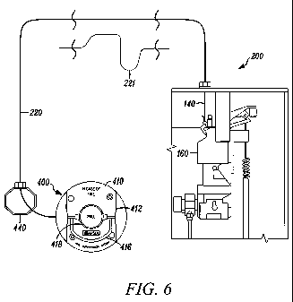
[0082] Fig. 6 is a block diagram illustrating a mechanical system for
connecting the pull handle 416 of
pull station 400 to the release mechanism 160 of the fire suppression system
using a wire rope 140
contained within a flexible conduit 220. An example of the release mechanism
160 is a panel, such as the
Ansul AUTOMAN panel. Another example of the release mechanism 160 is a valve.
Alternatively, flexible
conduit 220 may be used to connect pull station 110 (shown in Fig. 1) with the
release mechanism 160.
[0083] The flexible conduit 220 may be composed of a variety of types of
conduits, such as a Bowden
conduit and a braided conduit, as shown in more detail in Figs. 5A-C. However,
the flexible conduit is not
limited to these types of conduits. The flexible conduit 220 may include a
liner, a liner wrap, and an outer
jacket. Though, the flexible conduit 220 does not need to include each of the
liner, the liner wrap and the
outer jacket. For example, the outer jacket need not be included in the
flexible conduit. The flexible conduit
220 and wire rope 140 are coaxial mechanical devices whereby the wire rope 140
is disposed to slide axially
within the liner of the flexible conduit 220. The flexible conduit 220 may be
routed in non-standard
configurations 221 as shown in Fig. 6. Further, the flexible conduit 220 may
be used in combination EMT
130 and/or pulley elbows 150 to couple wire rope 140 between, for example,
structures such as the pull
station 400 and release mechanism 160. The wire rope 140 may be composed of a
metal, such as an
aircraft quality stainless steel braided wire rope with, for example, 7x7
braiding. The braiding of the wire rope
may allow for the wire rope to be more bendable. Alternatively, the wire rope
may have different braiding or
no braiding at all.
[0084] The liner may comprise a material with a low coefficient of friction.
For example, the liner may
be composed of in part or whole a plastic material such as, for example, an
acetal polymer, a polyethylene
polymer, a PVC polymer, or a Teflon fluoropolymer. In this manner, the liner
may reduce the coefficient of
friction between the liner and the wire rope whereby reducing the force
required to slide the wire rope
through the flexible conduit.
[0085] The liner wrap may comprise metal or composite, and may be a wire braid
(such as a cross-
weave), a flat wrap, or a wire wrap. The liner wrap may provide structural
support to the flexible conduit 220,
8
CA 02679863 2009-09-01
WO 2008/109345 PCT/US2008/055307
such as structural support to the liner. The liner wrap may be a mesh-type
structure, with a plurality of holes
there through. As discussed above, the flexible conduit may include an outer
jacket. The outer jacket may
comprise a polypropylene material, a PVC material, or other suitable plastics
materials. The outer jacket,
which may be free of holes, may be used for a variety of purposes. For
example, the outer jacket may be
used to form an impermeable and ductile outer sheathing for flexible conduit
220. The outer jacket may also
be colored (such as red) thereby serving as a visual warning mechanism to
identify this flexible conduit as
"SAFETY RELATED". In addition to the red color, indicia (such as printed text)
may be printed on the outer
jacket. For example, black text may be printed against the red outer jacket
indicating the "fire suppression
cable - do not disturb".
[0086] One example of flexible conduit may include Bowden lined conduit 500,
illustrated in Fig. 5A.
The Bowden lined conduit 500 may include an outer jacket 502 composed of PVC.
The outer jacket 502
may be a 0.197" outer diameter, for example. The Bowden lined conduit 500 may
also include a wire wrap
506, acting as a liner wrap. And, the Bowden lined conduit 500 may include a
polyethylene liner 504 acting
as a liner. The wire rope 140 may be inside of the polyethylene liner 504.
Another example of flexible
conduit may include a braided conduit 305, illustrated in Figs. 5B-5C. The
braided conduit 305 may include
a polypropylene outer jacket 310. The polypropylene outer jacket 310 may have
a 0.203" outer diameter.
The braided conduit 305 may include a wire braid 330, such as a 12-16 wire
braid, acting as a liner wrap.
And, the braided conduit 305 may include, an acetal liner 320 acting as a
liner. Still another example of
flexible conduit may include a long lay conduit with a polyethylene jacket of
0.187" outer diameter, a wire
wrap, and a polyethylene liner. The flexible conduits illustrated in Figs. 5A-
5C may easily be bent without the
need for permanent deformation (or reshaping) of the liner or liner wrap.
[0087] Further, a lubricant may be used to reduce the coefficient of friction
between the wire rope 140
and the liner. In particular, a lubricant (such as a Silicone lubricant) may
be added to one of, or both, the
flexible conduit 220 and the wire rope 140. For example, the interior surface
of the liner and/or the exterior
surface of the wire rope 140 may be coated with a lubricant to reduce the
coefficient of friction between the
wire rope 140 and the liner. Alternatively, the liner may be attached to the
wire rope 140. For example, the
wire rope 140 may be coated with a lubricant that subsequently solidifies (or
partly solidifies). In this way,
the wire rope 140 and/or the flexible conduit 220 may include a liner. As
discussed above, the flexible
conduit 220 allows the wire rope 140 to be pulled at the pull station 400 in
order to activate the release
mechanism 160. The following is an equation of the forces associated with the
pull station 400 and the
release mechanism 160:
[0088] Fl = F2 x euskB
[0089] where Fl is the force at the pull station 400;
[0090] F2 is the force at the release mechanism 160;
[0091] usk is the coefficient of friction; and
[0092] B is the radians of total flex where 360 degrees = 2 pi radians for the
flexible conduit 220 routing.
9
CA 02679863 2009-09-01
WO 2008/109345 PCT/US2008/055307
[0093] As discussed above, the liner of the flexible conduit 220 may be
composed of a Teflon "
fluoropolymer, which has a usk (coefficient of friction) of .040. According to
the equation above, a flexible
conduit 220 with no bends results in a force Fl at the pull station 400 of 1
pound to generate a 1 pound force
at the release mechanism 160 (basically, no loss in the force generated from
the pull station 400 to the
release mechanism 160). Further, according to the equation shown above, a
flexible conduit 220 with a
summation of angular curves of 4.7 radians (270 degrees) requires a force Fl
at the pull station 400 of 1.21
pounds to generate a 1 pound force at the release mechanism 160. In this way,
even though the flexible
conduit 220 has considerable bends in it, the amount of force necessary at the
pull station 400 to generate a
1 pound force at the release mechanism 160 is substantially the same and not
considerably higher than the
flexible conduit 220 with no bends in it. Therefore, comparing the low
friction flexible conduit to other
conduits of higher friction, the flexible conduit 220 does not cause the
operator of the pull station 400 to exert
an inordinate amount of force to activate the release mechanism 160.
[0094] The fire suppression system may also include a pulley block 610 of Fig.
9A or 710 of Fig. 9B.
Pulley blocks 610 and 710 may be installed proximate to the pull station 400
such as being connected to the
pull station as shown in Figs. 7A-D, 8A-D, 17A-B. Pulley blocks 610 and 710
may be connected to the pull
station so that the wire rope 140 exits from the pulley block in any of
multiple directions. For example, if the
pull station 400 may be mounted flush to a wall, the wire rope 140 may exit
from the pulley block 610 or 710
in any upward direction (toward the ceiling), a downward direction (toward the
floor), to the right, and to the
left.
[0095] The pulley blocks 610 and 710 may allow for installation in a variety
of boxes, such as a
standard electrical box 440, a deep electrical box 445, or no box. For a
standard electrical box, the pulley
blocks 610 and 710 may be configured in a first orientation (as shown in Figs.
7A-B and 8A-B) for a shallow
box. In a first configuration for a standard electrical junction box, portion
615 or 715 may be pressed into the
faceplate 410 in receiving location 420 of the pull station (shown in Figs. 9A-
B and 16D). The portions 615
or 715 may be multi sided, such as square in shape, and may include a series
of grooves 726 or snap fitting
features 627 to provide positive engagement of the pulley blocks 610 and 710
into the faceplate 410. In this
manner and with a square configuration, the pulley blocks 610 and 710 may be
pushed into the faceplate
410 in any one of four positions, thus allowing the cable exit points to exit
the junction boxes 440 and 445 in
any one of four holes 430 or 431. In a second configuration for a deep
electrical junction box, pulley box
portions 620 or 720 may be pressed into the faceplate 410 of the pull station
(shown in Figs. 7C-D and 8C-
D). The portions 620 or 720 may be multi sided, such as square in shape, and
may include a series of
grooves 726 or snap fitting features 627. In this manner and with a square
configuration, pulley blocks 610
and 710 may be pushed into the faceplate 410 in any one of four positions,
thus allowing the cable exit point
of pulley blocks 610 and 710 to exit the junction box 440 and 445 in any one
of four holes 430 or 431
respectively. The junction box 440 and 445 may include a box bottom 436 and a
box screw boss 437. The
junction box 440 may interface with EMT 130 using a conduit-to-junction box
coupling 131 (as shown in Fig.
17A) or may interface with flexible conduit 220 using a strain relief (not
shown in Fig. 17B).
CA 02679863 2009-09-01
WO 2008/109345 PCT/US2008/055307
[0096] The pulley blocks 610 and 710 are uniquely configured to ensure that
field cable entering the
shallow or deep electrical junction boxes may enter on centerline of the
junction box access holes 430 or 431
as illustrated in Figs. 17C-D.
[0097] The pulley blocks 610 and 710 shown in Figs. 10A and 10B may include a
pulley 640 and 740
with bearings, or a pulley with a low friction bushing, in order to reduce the
force necessary to pull the wire
rope 140 out of the pull station when activating the pressurizing control
cabinet 200, release mechanism 160.
The pulley 640 or 740 may be connected to pulley block 610 or 710 using pulley
axle screw threaded boss
and pulley axle retaining clip 147. An example of the means by which to
connect the pulley includes using
pulley axle shaft 641 and threaded pulley axle 642 (for pulley 640), or pulley
axle shaft 741 and threaded
pulley axle 742 (for pulley 740). Alternatively, the pulley axle retaining
clip 147 need not be used. For
example, threaded pulley axle 742 may be turned into the pulley block to
secure the pulley 640 or 740. Fig.
10A further illustrates a pull knob stem receiver 725, a cleat retaining boss
for a flexible cable 745, and a
cleat retaining boss for a pulley axle 747. Fig. 10C further illustrates a
pull knob stem receiver 625, a snap
cleat relief 626, a snap cleat locking surface 628, and a cleat retaining boss
for a flexible cable 645.
[0098] The pulley blocks 610 and 710 may connect to the flexible conduit 220
using an integral or
assembly assisting retaining clip 145. The retaining clip 145 may contain
teeth or cleats 146 dimensioned
such that the inner diameter (ID) of the clip is slightly less than the outer
diameter (OD) of the flexible conduit
220 outer jacket 310 to enable positive engagement of the teeth or cleats 146
with the outer jacket 310. The
teeth or cleats 146 may be angled in such a way to allow the flexible conduit
to be inserted into the pulley
blocks 610 or 710 using reasonable force by hand. Based on the predisposed
angle of the teeth or cleats
146 as shown in Figs. 10A and 10B, removal of the flexible conduit 220 from
the pulley blocks 610 or 710 is
made difficult and thus may require the use of a special tool. Alternatively,
a crimp may be used in place of
the retaining clip 145 to connect the flexible conduit 220 to the pulley
blocks 610 or 710. The pulley blocks
610 or 710 may also include proper circular interface bosses at each wire rope
140 exit point to enable the
pulley blocks 610 or 710 to couple directly to EMT conduit compression
fittings or other forms of conduit
castings or couplings.
[0099] The fire suppression system may include a faceplate 410 that is coupled
to pulley blocks 610
and 710. The faceplate 410 may include lettering in one or more languages. The
faceplate 410 may be
coupled to pulley blocks 610 and 710 in several ways, including using one or
more set screws 417 or snap
lock features 627 (illustrated in Fig. 10C) that may couple the pulley blocks
610 and 710 into engagement
with the faceplate 410. Alternatively, instead of set screws 417, a crimp
connector may be used. The
resulting combination is a faceplate 410/pulley block 610 or 710 coupled as an
assembly. When the
faceplate 410 is configured with the snap lock feature as shown in Fig. 9A,
assembly of the pulley block 610
into the faceplate 410 may be accomplished by hand without tools. The snap
lock feature, as described
herein and depicted in Fig. 9A, enables a faceplate-to-pull knob snap lock
feature 425 to be utilized for
locking the pull knob body 418 in a normal rotational orientation as shown in
Figs. 11 C-D and 16E. The
11
CA 02679863 2009-09-01
WO 2008/109345 PCT/US2008/055307
snap lock feature 425 may be used to engage the pull knob body 418 into place
once the pull knob body 418
is rotated into its final position. In this way, the pull knob body 418 may be
rotated relative to the faceplate
410. Alternatively, the pull knob body 418 may remain stationary and the
faceplate 410 may be rotated.
The faceplate 410 may include one or more faceplate center pulley block
receiver walls 421 and a faceplate
center pulley block receiver step lock 422, as shown in Fig. 16E.
[00100] The snap lock feature 425 enables the pull knob body 418 to be
rotated, such as rotated
sufficiently clockwise to allow the break rod 412 to be inserted into the pull
knob body 418 in preparation for
setting the pull station to a normal orientation as shown in Figs. 11A-D.
Insertion of the break rod 412 may
thus be accomplished in areas where there is adequate wall space on each side
of the pull station and also
within the narrow wall confines. This is illustrated in Figs. 12A-C in which
wall 117 is proximate to the
faceplate 410. In order to insert break rod 412, the pull knob body 418 is
rotated clockwise (illustrated in Fig.
12A), and after installation of the break rod, rotated counterclockwise
(illustrated in Fig. 12B). While the pull
knob body 418 is being rotated counterclockwise towards the snap lock
position, the snap lock cleat 425 may
remain compressed until it moves into the corresponding relief 409 contained
within the pull knob body as
shown in Figs. 10D-1 and 13E.
[00101] The pull station 400 includes pull handle cap 390, cap snap fit boss
391, and cap body snap
fit receiving boss 392, as shown in Fig. 9a. A crimp stop 141 may be used to
hold pull handle cap 390. The
crimp stop 141 is one example of a cable compression connection. Another
example of a cable compression
connection may comprise a compression fitting, which may be used in place of
crimp stop 141. Fig. 9A
further shows a cross hole for break rod 401, a relief hole for wire rope
stopper 402, a ring handle hole 403,
and a tool slot 404.
[00102] The faceplate 410 may contain one or more protective side walls 411,
such as one on each
side of the pull knob body 418 and pull handle 416 assembly as shown in Figs.
16B and 16D. The
protective walls 411 may provide a robust barrier to protect the pull knob
body 418 and pull handle 416
against inadvertent side impact by foreign objects. These protective side
walls 411 may also provide slots
413 for receiving the ends of the break rods 412 when installed, illustrated
in Fig. 17A-C. Further, the
faceplate 410 may include a pull handle circular race of faceplate 423 and a
pull knob set screw threaded
boss 424.
[00103] Activation of the pull station may be accomplished by pulling the pull
knob body 418 away
from the pull station 400. This action may cause the break rod 412 to fracture
allowing the pull knob body
418 to move away from the faceplate 410 and thus moving the wire rope 140
through the flexible conduit
220, thereby activating the release mechanism 160. Coupling of the wire rope
140 to the pull knob body 418
may be accomplished in several ways, such as shown in Fig. 9B. Two methods are
provided for illustration
purposes only. The first method, as illustrated in Figs. 13A-C, uses one or
more set screws 417 to secure
the wire rope 140 into fixed or permanent configuration with the pull knob
body 418. In this configuration, the
wire rope 140 may be threaded into the wire rope recess 426 of the pull handle
cable boss 428, such as
12
CA 02679863 2009-09-01
WO 2008/109345 PCT/US2008/055307
shown in Fig. 13C. Set screws 417 may be tensioned against the wire rope 140
to cause a sufficient binding
on the wire rope to prevent it from being removed, such as shown in Fig. 6. As
discussed above, set screws
417 need not be used and alternative methodologies, such as using a crimp
connector, may be used. The
second method, as illustrated in Figs. 13D-F, uses a compression fitting 141
to create an oversized end of
wire rope coupling to inhibit or prevent the wire rope 140 from being removed
from the pull knob body 418.
In this configuration, the OD of the compression fitting 141 may be larger
than the OD of the wire rope
access hole 426 in order that removal of the wire rope 140 from the pull knob
body 418 is inhibited or
prevented.
[00104] The faceplate 410 may also contain containment boundary diaphragms 415
(illustrated in
Fig. 16D) located in each faceplate 410 mounting screw boss 414, (illustrated
in Figs. 9A-B and 16D). The
containment boundary diaphragms 415 may be used to reduce or minimize any
contaminate such as grease,
dirt or grime from penetrating the faceplate 410 outer surface and entering
into the working components
and/or wire rope conduit 140 or 200 sections of the pull station assembly,
such as shown in Fig. 11A.
[00105] The faceplate 410 and/or the pull handle cap 390 may further include
various indicia, such
as words, as shown in Figs. 9A-B and 10D. The indicia may be of a color that
is different from another
portion of the faceplate 410 and the pull handle cap 390.
For example, the color may be red, fluorescent, or glow in the dark in order
to differentiate the words (and
the faceplate) from the surroundings (such as an aluminum background). The
break rod 412 may be
composed of plastic or glass and therefore may be transparent or opaque. The
color on the faceplate 410
may be highlighted when viewed through the break rod 412. Moreover, a part (or
all) of the pull handle 416,
break rod 412, screw boss 414, or containment boundary diaphragms 415 may be
of a color that is different
from another portion of the pull handle 416, break rod 412, screw boss 414, or
containment boundary
diaphragms 415. Or, the pull handle 416, break rod 412, screw boss 414, or
containment boundary
diaphragms 415 may entirely be red, fluorescent, or glow in the dark in order
to differentiate it from an
adjacent part. Finally, the colors of two parts that are designed to mate may
be selected such that the colors
match when installed properly (e.g., continuous color red for screw boss 414
and containment boundary
diaphragm 415 if they are installed properly) or such that the colors are
different when installed properly
(e.g., color red next to color aluminum when screw boss 414 is installed
properly with containment boundary
diaphragm 415).
[00106] The faceplate 410 may further be adapted to serve as a storage
mechanism for service
items, such as extra break rods 412. One method is shown in Figs. 16A and 16B.
In the event that the pull
station 400 needs to be reconfigured or reinitialized, such as by inserting a
new break rod, the hardware
used for the reinitializing may be stored proximate to the pull station 400,
such as storing additional break
rods 412 on an underside of the faceplate 410, as shown in Fig. 16A. The break
rods 412 may be stored at
a 90 angle to that depicted in Figs. 16A and 16C.
13
CA 02679863 2009-09-01
WO 2008/109345 PCT/US2008/055307
[00107] When the pull station 400 is installed in the field, the technician
may often leave extra wire
rope 140 inside the pressurizing control cabinet 200. This extra length of
wire rope 140 may have the effect
of allowing the pull knob body 418 to move away from the pull station 410
without activation of the release
mechanism 160. A wire rope auto tensioning device may be used to control the
"dead band" of wire rope
140 and maintain the wire rope 140 under tension, though this is not required.
One example of an auto
tensioning device comprises an auto tensioning spring 142, illustrated in
Figs. 15A-D. The auto tensioning
spring 142 may be used to reduce the "dead band", as shown in Figs. 15A-B. The
auto tensioning spring
142 may allow the technician the ability to field test the conduit 130 or 220
routing without activating the
system, as illustrated in Fig. 15D, by partial movement pull testing from the
pull station. For example, a
single technician located at the pull station 400 may pull the pull handle 416
in order to test the device. If
after pulling the pull handle 416, the handle returns to its position (i.e.,
springs back), then the technician may
determine that the auto tensioning spring 142 is operational and the wire rope
is properly configured. The
auto tensioning spring 142 may further ensure activation of the system upon
deployment of the pull knob
body 418, as illustrated in Fig. 15C, by extended full movement.
[00108] As shown in Fig. 15A, the auto tensioning device (such as the auto
tensioning spring 142) is
located proximate to the release mechanism 160. Alternatively, the auto
tensioning device may be located at
any point along the path of the wire rope 140 from the pull station 400 to the
release mechanism 160. The
auto tensioning device may comprise a variety of shapes, such as a "Z" shaped
spring, as shown in Fig. 15A.
[00109] The equation F, = F2eisk6 may be used to describe the characteristics
of the flexible conduit
system shown in Figs. 6 and 14. F, may be the force at one end of the wire
rope (such as where the wire
rope 140 is connected to the pull station 400), and F2 may be the force at the
other end of the rope (such as
where the wire rope 140 is connected to the release mechanism 160 of the
pressurizing control station 100
or 200). The coefficient of static or kinetic friction may be represented by
usk. The angle B may be
expressed in radians.
[00110] As discussed above, there are a variety of ways by which the flexible
conduit 220 (and the
wire rope 140 inside the flexible conduit) may be attached to various
structures in the fire suppression
system. One example is depicted in Figs. 18A-E. Fig. 18A depicts a perspective
view of a PG9 cap 800. As
discussed in more detail below, the PG9 cap 800 works in combination with
compression fitting 810 and
strain relief 820 to connect the flexible conduit 220 and the wire rope 140 to
structures within the fire
suppression system, such as junction boxes, valves, AUTOMAN panel, etc.
[00111] The PG9 cap 800 includes a hole 802. As discussed in more detail
below, the hole 802 may
have a radius large enough to pass wire rope 140 through and a radius small
enough so that the flexible
conduit 220 cannot pass through. For example, the hole 802 may be sufficiently
small so that the liner of the
flexible conduit 220 (such as polyethylene liner 504 and acetal liner 320)
cannot pass through. A further
example may be where the hole 802 diameter is equivalent to the outer jacket
diameter of the flexible conduit
502 and 310 to create an effective flexible conduit guide into the junction
boxes 440 or 445 (as viewed in
14
CA 02679863 2009-09-01
WO 2008/109345 PCT/US2008/055307
Figs. 7B and 7D). Further, the PG9 cap 800 has an interior surface that
includes threading 804. As
discussed in more detail below, a portion of the strain relief 820 may connect
to the threading 804.
[00112] Fig. 18B depicts a perspective view of the compression fitting 810.
The compression fitting
810 includes compression fitting cap 812 and compression fitting main body
814. The compression fitting
main body 814 may be connected to a structure within the fire suppression
system, such as junction box
120, using bolt 816.
[00113] Fig. 18C depicts an exploded view of the compression fitting 810 and
the PG9 cap 800. The
PG9 cap 800 may be sandwiched in between the compression fitting cap 812 and
the compression fitting
main body 814. The compression fitting cap 812 may then be attached to the
compression fitting main body
814, such as by screwing the compression fitting cap 812 onto the compression
fitting main body 814 via
threads 817 on the compression fitting main body 814 and threads on an
interior surface of the compression
fitting cap 812 (not shown). The outer diameter of the PG9 cap 800 may be less
than the inner diameter of
the compression fitting cap 812 so that the compression fitting cap 812 may
slide onto the PG9 cap 800.
Further, the outer diameter of the PG9 cap 800 may be less than or equal to
the outer diameter of the
compression fitting main body 814. In this way, when the compression fitting
cap 812 is screwed onto the
compression fitting main body 814, the PG9 cap 800 may be securely compressed
in between.
[00114] Fig. 18D depicts a perspective view of the strain relief 820. The
strain relief 820 includes
strain relief cap 822 and strain relief main body 824. The strain relief cap
822 includes a hole 826 by which
the flexible conduit 220 may be attached. The strain relief main body 824
includes threading 828 for
threading with the threads 804 of the PG9 cap 800. In this way, the strain
relief 820 may be attached.
[00115] Fig. 18E depicts a side view of the strain relief 820 and the
compression fitting 810 prior to
attachment of the strain relief 820. As shown, the flexible conduit may be
attached to the strain relief 820.
And, using PG9 cap 800, the wire rope 140 may be guided into the junction box
120.
[00116] Considering Teflon to steel usk = 0.04 (such as where the liner 320
is composed of Teflon
and the wire rope 140 is composed of steel), F2 = 6 lbs and F, = 40 Ibs, then
B = 47.4 radians or 2717
degrees. Without a liner and/or lubricant, the coefficient of friction is
higher, such as usk = 0.15. Using the
same forces of F2 = 6 lbs and F, = 40 Ibs, the B = 12.6 radians or 724
degrees. Comparing these two
examples illustrate the significant impact that a lower coefficient of
friction has on the flexible conduit
constraints. In the example using usk = 0.04, the flexible conduit may be bent
30 times at right angles
whereas the example using usk = 0.15 (without the liner), the flexible conduit
may be bent at the same angle
only 8 times.
[00117] The flexible conduit 220 in the fire suppression system may be easier
to install than the EMT
130 and the 90 degree pulley elbows 150 shown in Fig. 1. Further, the flexible
conduit 220 still provides a
reliable system similar to the fire suppression system shown in Fig. 1. The
flexible conduit system was
cycled more than 8,000 times without signs of degradation. The system passed a
500 cycle test with 150
feet of lined and coated Bowden conduit, eight 90 degree bends with a 3"
radius, 15 pulley elbows, a pull
CA 02679863 2009-09-01
WO 2008/109345 PCT/US2008/055307
station with a built-in pulley block, and a 6 lb load at one end, the
resulting force on the other end being
37.23 lbs on average with a standard deviation of 1.45 lbs. With a similar
setup, except with a pull station
having an ultrahigh molecular weight polyethylene (UHMW) busing and a three
pound load, the resulting
force was 30.83 pounds with a standard deviation of 1.25 lbs.
[00118] As discussed above, the flexible conduit may be connected to the Ansul
AUTOMAN panel,
gas valve, corner pulleys, electrical box, EMT conduit, etc. For example, the
flexible conduit may be
connected between the Ansul AUTOMAN panel and the pull station, up to 140 ft
and four 90 bends. When
the flexible conduit is used to make 90 bends, these bends may start from the
AUTOMAN panel or gas
valve, with some or no mechanical 90 elbows being used in between these
bends. If more than four 90
bends are used, then mechanical pulleys may be used. The flexible conduit may
also be connected between
the Ansul AUTOMAN panel and the gas valve, up to 75 ft and four 90 bends and
four corner pulleys. The
flexible conduit may be placed along the same path as the EMT conduit would
normally be run. Stainless
steel rope may be routed through the flexible conduit. The flexible conduit
may be distanced from hood or
other high temperature items by more than 6 inches. These examples are
provided for illustration purposes
only.
[00119] Alternatively, instead of using wire rope 140 to connect the pull
handle 416 to the release
mechanism 160, other means may be used. For example, activation of the pull
handle 416 may in turn
activate a circuit (such as a switch) which could send a signal to a releasing
mechanism. The signal may be
an electrical signal transmitted via an electrical wire. Or, the signal may be
a wireless signal, which may be
transmitted via a transceiver and received at the release mechanism (such as
the Ansul AUTOMAN panel,
which may include a wireless receiver and/or transmitter).
[00120] Moreover, instead of using wire rope 140, a fiber optic cable may be
used. For example, the
pull station may be connected between a first fiber optic cable and a second
fiber optic cable. Specifically, a
light source may be connected to the first fiber optic cable, sending a beam
through the first fiber optic cable.
A panel may be connected to the second fiber optic cable. In the event that
the pull station is not activated,
light traveling through the first fiber optic cable may be interrupted,
indicating to the panel that the pull station
has not been activated. In the event that the pull station is activated (such
as by pulling the pull handle 416),
light traveling through the first fiber optic cable may not be interrupted,
indicating to the panel that the pull
station has been activated.
[00121] While various embodiments of the invention have been described, it
will be apparent to
those of ordinary skill in the art that many more embodiments and
implementations are possible within the
scope of the invention. Accordingly, the invention is not to be restricted
except in light of the attached claims
and their equivalents.
16