Note: Descriptions are shown in the official language in which they were submitted.
CA 02680457 2009-09-10
. '
=
Spreading Device for Spreading Out Fiber Filament Bundles, and Spreading
Method Carried Out Using Same
The invention relates to a spreading device to spread fiber filament bundles
to form a
flat fiber band. The spreading device according to the present invention is
particularly
suited for use in a method for manufacturing a preform for a load path aligned
fiber
composite structure. Moreover, the invention relates to a spreading method
carried out
using such a spreading device.
At the construction of vehicles of all kinds, particularly at the construction
of aircrafts
and spacecrafts, but also in other branches of industry such as mechanical
engineering,
there is an increasing need for strong and yet lightweight, cost-efficient
materials.
Especially fiber composite materials offer an outstanding lightweight
construction
potential. The principle resides in the fact that particularly high-strength
and stiff fibers
are embedded in a matrix in a load path aligned fashion, thus producing
components
having outstanding mechanical properties by using previous techniques and
having a
weight which at a comparable performance is typically 25% less than that of
aluminum
structures and 50% less than steel structures. A drawback is the high material
costs and
particularly the laborious and mainly manual fabrication.
Accordingly, there is a desire for an automated manufacture facilitating
machine
positioning of the fibers in space. Nowadays, fiber-reinforced plastic
materials are
characterized by an extremely high strength and stiffness at a low weight,
particularly if
oriented long fibers, for instance carbon fibers, are used. They also have a
high weight-
specific energy absorption potential and good fatigue characteristics.
Up to now this is achieved by endless fibers being incorporated in a matrix
(e.g. epoxy
resin) in a load path aligned fashion. Depending on the direction of
reinforcement,
anisotropic materials having direction-dependent mechanical properties can be
produced. For instance, a material can have characteristics which are
different from
each other in the length and in the width of the material. Already today, a
high
CA 02680457 2009-09-10
2
percentage of the structural weight In modern aircrafts and spacecrafts, is
made up of
fiber-reinforced plastic materials.
Currently, the most important manufacturing process is based upon the so-
called
prepreg technology. This technology involves positioning the reinforcing
fibers in a
parallel (unidirectional) fashion and embedding the fibers in a matrix. After
a curing step,
semi-finished products are produced which are rolled up as a thin layer.
During
processing, these layers are cut corresponding to the contour of the component
and are
laminated in a tool layer by layer and preferably by hand. Thereafter, curing
takes place
under pressure and temperature inside an autoclave. The resulting components
exhibit
a very high light construction potential, but the manufacture is laborious and
expensive.
For this reason material searchers have for long dealt with the question in
which way
fibers can be positioned aligned to the load path and three-dimensionally and
with a
contour which matches the final contour of the component as closely as
possible, in an
automated process.
To produce fiber composite structures with load path aligned fibers, so-called
preforms
as textile semi-products have been manufactured up to present for selected
applications
in addition to prepregs. These are mostly two- or three-dimensional structures
having a
load path aligned fiber orientation. Up to present endless fibers are placed
in the load
direction and prefixed by using means and techniques from textile engineering,
normally
sewing, knitting or the like. Examples of devices and processes for producing
such
preforms are disclosed in DE 30 03 666 Al, DE 196 24 912, DE 197 26 831 Al and
DE
100 05 202 Al.
However, the known processes for manufacturing preforms are complicated
concerning
their implementation and process technique. Particularly for components where
curved
load path lines with a varying density are to be expected, it is not possible
with previous
processes to manufacture a correspondingly load path aligned component.
Particularly,
the fibers cannot be oriented arbitrarily along defined curved paths and the
fiber content
cannot be locally varied.
CA 02680457 2009-09-10
. . "
3
For manufacturing the textile semi-finished parts, so called rovings are
interwoven to
form the textile preform by using the above explained preform manufacturing
techniques. For example 12k rovings with 12000 single filaments are used. A
uniform
penetration of such rovings by the material of the matrix is very complicated
to
accomplish. Alos, at the location of the rovings high fiber concentrations
exist with only
a low fiber moiety in between, so that it is difficult to vary the rate of
fibers locally
according to the individual requirements of the component.
Different spreading techniques for spreading fiber filament bundles are known
in textile
engineering for completely different fields of application. In figure 4 the
basic principle of
a conventional spreading technique known from DE 715 801 A is shown. Here, a
fiber
strand 14 consecutively passes a bent rod 76 and then a straight rod 78. The
combination of a straight and a bent rod in this known radius spreaders as
shown in
figure 4, causes a redirection of the tension force acting on the fiber. Now
also a force is
effective that presses the fiber onto the bent rod. At the highest point of
the deflection
the highest force acts on the filaments. The force decreases with an
increasing
distance from this point, i.e. the filaments can evade this load if moving
outwardly on the
bent rod. However, the result of the spreading operation is dependent on the
tension
force acting on the fiber, the friction between the fiber and the rod, the
position of the
rods relative to each other and the bending of the rod. If the bending is
extreme, the
difference of the acting forces between the highest point and an outer
position is high to
an extent that the surface friction of the rod is no longer important. The
filaments will
abruptly move outwardly, i.e. the fiber strand 14 would slip off or split. If
the bending is
too low, the bending ratio will be too low. Thus the result of the spreading
operation is
very irregular with an irregular fiber distribution. In particular, the result
of the spreading
operation is very much dependent on the quality of the material.
In view of the above-mentioned prior art it is an object of the invention to
provide a
spreading device and a spreading method for spreading fiber filament bundles
to form a
CA 02680457 2011-12-20
4
flat fiber strand, in which device and method the material quality only has a
miner
influence on the result of the spreading operation.
With the spreading method and the spreading device according to the invention
s problems concerning the quality of the material of fiber filament bundles
to be spread
are solved by the fiber filament bundle being repeatedly placed again and
again onto at
least one convexly bent spreading edge. For this purpose, the spreading device
at least
includes one convexly bent spreading edge moving with at least one direction
component perpendicular to the longitudinal extension of the fiber filament
bundle
relative to the fiber filament bundle in such a manner that the same is placed
under
tension onto the convexly bent spreading edge and thereafter moves again with
at least
one direction component perpendicular to the fiber filament bundle away from
the fiber
filament bundle, so that the same becomes detached from the spreading edge.
In a method for manufacturing a preform having a load path aligned fiber
composite
structure, which is the method that is preferably used in the spreading
device, a preform
can be manufactured by first of all spreading a fiber filament bundle,
preferably a roving,
into a flat shape. From this bundle of spread fiber filaments a fiber band
piece ¨
hereinafter also referred to as patch ¨ is cut off preferably with a
predetermined length.
Thereafter, the fiber band piece is taken up by means of a lay-up device and
is placed
at a predefined position. There the fiber band piece is fixed by means of a
binder
material. The cutting, placement and fixing of fiber band pieces is repeated,
with the
fiber band pieces being placed and fixed at different predefined positions.
Preferably,
this is performed in such a way that from the several patches which are fixed
to each
other and/or to possible additional component parts of the preform the desired
preform
having a load path aligned fiber orientation is formed. In this way it is also
possible for
example to specifically reinforce also a part of a conventionally produced
preform by
patches being placed in a load path aligned fashion at positions which are
particularly
subjected to stress.
CA 02680457 2011-12-20
Generally, such a method ¨ which is also referred to as fiber patch preforming
technology ¨ enables by a special laying operation the lay-up of short fiber
pieces
(patches) exactly at their position. The required properties of the preform
can be
achieved through the orientation and the number of fiber pieces.
5
By means of the invention a fiber filament bundle, especially a roving, can be
spread
especially flatly and uniformly. Thus, by using the above-mentioned method,
thickenings
or other undesired fiber concentrations can be avoided, and the individual
filaments can
be better embedded in the matrix. But the invention can be used also for other
purposes
where a flat and uniform spreading of fiber bundles composed of individual
fibers is
desired.
As a filament bundle which is spread by means of the spreading device a
roving,
particularly a carbon roving, is preferred.
The spreading device according to the invention particularly enables
individual filaments
of a roving being spread more widely than with previous techniques.
Accordingly, in a
preferred embodiment a fiber band which is as flat as possible can be provided
from a
number of layers of juxtaposed individual filaments which is as small as
possible. For
this purpose, the spreading device in embodiment includes a spreading
installation and
a downstream loosening installation.
Embodiments of the invention will now be described in more detail with
reference to the
attached drawings wherein it is shown by
Figure 1 a schematic overview of a device for manufacturing a preform
for
producing load path aligned fiber composite structures;
Figure 1a a schematic view of an alternative embodiment of the device of
figure 1 at
a separation plane indicated by a chain line;
CA 02680457 2011-12-20
6
Figure 2 a schematic view of a pay-off device employed in a device
according to
figure 1 for paying off a fiber filament bundle processed in the device
according to figure 1;
Figure 3 a schematic perspective view of a position sensor for use in
a pay-off
device of figure 2 and its characteristic curve;
Figure 4 a perspective view of a spreading device for explaining the
principle of
operation of the spreading of a fiber filament bundle applied in a device
according to figure 1;
Figure 5 a schematic perspective view of a spreading device for use in
a device
according to figure 1;
Figure 6a a schematic lateral view of a loosening device for use in a
device
according to figure 1;
Figure 6b a schematic illustration of the principle of operation of the
loosening device
of figure 6a;
Figure 7 a schematic lateral view of a binder impregnation device for
use in a
spreading device;
CA 02680457 2009-09-10
7
Figure 8 a schematic lateral view of a combination of a cutting and
laying device
employed in one embodiment of a device for manufacturing a preform;
Fig. 9/10 schematic illustrations of the principle of operation of the
cutting device of
figure 8;
Figure 11 a schematic view of predetermined paths for the placement of
fibers by
one of the devices according to figure 1 or figure 8;
Figure 12 a series of fiber band pieces placed by the device according to
figure 1;
Figure 13 a schematic view of a preform to be manufactured in a device
according to
figure 1 or figure 8;
Figure 14 a schematic cross sectional view of a laying head for use in a
laying device
according to figure 1 or figure 8;
Figure 15 a bottom view of the laying head of figure 14 and
Figure 16 a detailed schematic perspective view of the laying device of
figure 8.
Figure 1 shows an overall representation of a preform manufacturing device
generally
designated by reference number 10. This preform manufacturing device allows
the
fabrication of a complicated textile semi-product with load path aligned fiber
filaments
for manufacturing fiber composite structures in an easy manner even if the
semi-product
has a complicated structure. Such textile semi-products are called preforms.
The
fabrication of these preforms takes place from individual short fiber pieces
that are fixed
with a binder material and cut off from a specially prepared strand of fiber
filaments or
fiber band. Accordingly, the preform manufacturing device can divided up into
a
preparation module 12 for the possible preparation of the fiber bind 14 and a
cutting and
CA 02680457 2009-09-10
8
laying module 16 for cutting-off and laying the fiber band pieces. A possible
separation
17 between these module 12 and 16 is indicated by a chain line.
Figure 1 illustrates a first embodiment of such a cutting and laying module
16; a second
embodiment of such a cutting and laying module 16 is illustrated in figure 8.
First of all the overall structure and the principle of operation of the
preform
manufacturing device 10 are explained with reference to figure 1. Thereafter
the
individual modules will be described with reference to the additional figures.
As can be seen from figure 1, the preform manufacturing device 10 includes a
pay-off
device 18, a spreading device 20, a binder impregnation device 22, a cutting
device 24,
a transfer device 26, a laying device 28 and a preform 30. These individual
devices 18,
20, 22, 24, 26, 28 and 30 can each work independently and can also be used to
serve
their intended purpose without the respective other devices. The present
disclosure
hence comprises the respective devices 12, 16, 18, 20, 22, 24, 26, 28, 30
individually
and alone.
The pay-off device 18 serves to supply a fiber filament strand, for example a
roving 32.
As described in more detail in the following, the pay-off device 18 is
constructed in a
manner such that the rovings 32 can be paid off without twisting. For
manufacturing
carbon fiber reinforced (CFC) components, a carbon roving is used in the
illustrated
embodiment.
The spreading device 20 serves to spread the individual filaments of the
rovings 32 as
widely as possible, to provide a fiber band 14 as flat as possible from a
number as small
as possible of layers of individual filaments placed side by side. For this
purpose the
spreading device 20 includes a spreading installation 34 and a loosening
installation 36
as will be explained in more detail further down.
CA 02680457 2009-09-10
9
The binder impregnation device 22 serves to provide filaments of the fiber
band 14
and/or individual fiber band pieces thereof with a binder material 38 serving
to fix the
fiber band pieces in the preform. In the embodiment illustrated in figure 1,
the binder
impregnation device 22 forms a part of the preparation module 12 and is thus
used to
provide the spread fiber band 14 with binder material 38. In embodiments of
the preform
manufacturing device 10 which are not further illustrated, a binder
impregnation device
22 can be additionally or alternatively associated to the cutting and laying
module 16, to
then provide the fiber band pieces already cut off with binder material 38.
The cutting device 24 is constructed for cutting off pieces of a defined
length from the
fiber band 14 (fiber pieces). In the following the individual fiber band
pieces are referred
to as patches 40, 40', 40".
The transfer device 26 serves to separate the patches 40 and to transfer the
same to
the laying device 28.
The laying device 28 is constructed in such a way that it can pick up
individual patches
40 and place them at predefined positions, in the present case on the preform
30. The
preform 30 serves to give the preform 42 a predetermined three-dimensional
surface
design.
The preform manufacturing device 10 further includes a control device 44
comprising
several controls 44a, 44a. The control device 44 controls the individual
devices or
installations 12, 18, 20, 22, 26, 30 in a manner such that the preform 42 is
formed from
the individual patches 40 in the manner of a patchwork quilt.
Accordingly, the preform manufacturing device 10 allows the following process
for
manufacturing a preform 42 for a load path aligned fiber composite structure
being
carried out automatically:
CA 02680457 2009-09-10
First of all a fiber filament bundle present in the form of a roving 32 is
spread and
activated with binder material 38 which in the present embodiment can be
thermally
activated. The binder-impregnated fiber band 14 thus provided is thereafter
cut into
pieces ¨ patches 40 ¨ having a predefined length. The patches 40 are separated
and
5 transferred to the laying device 28. The laying device 28 places each
patch 40 at the
respective predefined position 46 on the preform, and presses the patch 40
onto the
preform.
Accordingly, with this preform manufacturing device 10 a fiber patch
preforming
10 technology can be implemented which allows the exact positioning of
short fiber pieces
through a special laying process. The required properties of the preform 42
can be
achieved through the orientation and the number of fiber pieces. It is thus
possible to
orient fibers along defined curved paths and the fiber content can locally
vary.
By the placement of spread, short-cut fiber band pieces ¨ patches 40 ¨
optimally load
path aligned preforms 42 can be fabricated. A fiber cutting device 48 cuts the
specially
prefabricated binder-impregnated fiber bands 14 into short pieces and delivers
the
same to a vacuum band-conveyor 50 of the transfer device 26.
The delivery of the patches 40 from the vacuum band-conveyor 50 to a laying
head 52
of the lay-up device 28 takes place smoothly through a combination of suction
and
blow-off modules. The laying head 52 heats the patch 40 during the transfer to
its
placement position and thus activates the binder material 38. The laying head
52
presses the patch 40 onto the predefined position and then moves away by a
blow-off
pulse. Thereafter the laying head 52 returns to the initial position.
This technology allows the fully automatic production of complex fiber
preforms.
Parameters like fiber content, fiber orientation and curve radii can be
largely varied.
CA 02680457 2009-09-10
11
In the embodiments illustrated herein, spread carbon fibers are used instead
of textile
semi-products. The length of the fibers is very short (only a few centimeters)
compared
to pre-fabricated layings which use long fibers. By a specific positioning of
the short
fibers ¨ in the patches 40 ¨ high mechanical characteristics can be achieved
which are
similar to those of long fiber composites.
The short fibers can be relatively precisely placed along complex load paths.
Textile
cuttings as previously used for manufacturing such preforms merely allow
preferential
orientations being set. Thus with the technology herein described extreme
geometric
shapes can be produced. The manufacturing process is fully automated, and
thickness
variations within a preform and/or modified fiber volume contents can be
achieved.
In the embodiment of the preform manufacturing device 10 illustrated in figure
1, a laser
54 is used as a fiber cutting tool 48 within the cutting and laying module 16.
The laser is
process-controlled and is precisely movable with respect to the fiber band 14.
Further in
figure 1, a robot arm is indicated as a mechanical laying system 184 for
moving the
laying head. The preform 30 can be precisely moved and rotated in a defined
fashion
relative thereto, in order to produce complex 3D structures of preforms 42 in
a simple
way.
In summary, a principle of the embodiment of the fiber patch preforming
technology
herein described is based on spreading carbon fiber rovings 32 as widely as
possible,
coating them with binder powder and cutting them into pieces of a defined
length, so-
called patches 40, by employing a novel cutting technique. These patches are
then
picked up by a special laying device, placed at a predefined position and
fixed by
means of the binder material 38. In this way, the most varying component
geometries
and fiber architectures can be produced.
In the fabrication process herein described, spread fibers are used. Fiber
spreading
forms a basis for avoiding local accumulations of fiber ends within the later
composite
CA 02680457 2009-09-10
12
material, since the same cause stress concentrations which in the worst case
may
result in a failure of the component. Spreading reduces the thickness of the
rovings 32.
Thus more continuous fibers can reach the zone of influence of a fiber end and
compensate peaks of stress. Further, in an overlapping placement, the step or
shoulder
on the cutting end of a roving 32 is reduced. In a non-spread roving such a
step or
shoulder could be as high as 250 pm and could cause a deflection of the carbon
fiber
situated on top of it from the load path direction. Additionally, a zone rich
in resin could
be formed there, negatively affecting the strength of the material.
To carry out the spreading operation as effectively as possible, twisting of
the roving 32
shall be avoided, since filaments running transversely could again constrict a
spread
roving. The tension within the roving 32 in its spread state should be
constant, since the
spreading width and the spreading quality could be influence by tension
differences.
The pay-off device 18, which is described in more detail in the following with
reference
to figure 2, serves to enable delivery of a roving 36 in a non-twisted state
from a supply
reel 56 and to compensate the oscillating movement of the roving 32 during its
withdrawal from the supply reel 56. For this purpose the pay-off device 18
comprises a
movable support 58 of the supply reel 56 which is so designed that the supply
reel 56
will correspondingly join up the position of the part of the roving 32 just
being paid off,
so that the pay-off position remains as constant as possible.
For this purpose, the support 58 comprises a carriage 62 supported along a
linear
guideway 60. The carriage 62 is movable by means of stepping motors and, in
the
illustrated embodiment, by means of a drive screw 64 in the direction of the
rotation axis
of the supply reel 56. The carriage 62 is driven by a motor 66 with an
integrated control.
A sensor 68 monitors the current position 70 of the roving 32 and thus
controls the
rotation of the motor 66.
CA 02680457 2009-09-10
13
A photodiode 72 which is illustrated in figure 3 together with its
characteristic curve
serves as a sensor 68. A diode line of the photodiode 72 registers the shadow
of the
roving 32 and outputs the position via an amplifying circuit (not further
shown) as an
analog signal. The center of a shadow corresponds to a particular voltage as a
function
of the position. The analog signal is transmitted as a bipolar tension signal
to the control
of the motor 66, with 0 Volt corresponding to the center of the sensor.
Additionally, the
sensor 68 is exposed to a flash from an IR-LED spotlight at a particular
frequency, for
example 10 KHz, to prevent the measuring signal from being influenced by
ambient
light. This sensor 68 is optimized for the special requirements of a pay-off
operation
1.0 compensating the position of the roving 32 on the supply reel 56 and
also allows still
further adjustments such as the displacement of the center and the adjustment
of the
bending. The combination of a spatial resolution photodiode 72 and a
controlled servo
motor 66 has the advantage that the counter movement is caused in dependence
of the
current speed of movement of the roving 32. Relatively low-speed compensation
movements are caused at low pay-off speeds, whereas high pay-off speeds cause
correspondingly fast counter movements. This enables the roving 32 being
unreeled
mainly oscillation-free as a flat band or tape 74. On the end of the pay-off
device 18
the roving 32 passes in an S-like movement around two little reels 75 - in the
present
case two waisted stainless steel reels which additionally calm final
oscillations.
Differently from the way illustrated in figure 1, the pay-off device 18 can
also be
operated completely autonomously, i.e. independently of the remaining modules
and
normally only requires power supply, e.g. an electrical connection.
After the pay-off device 18 the roving 32 passes a spreading line in the
spreading
device 20.
As already mentioned above, the spreading device 20 comprises the spreading
installation 34 which is shown in more detail in figure 5 and the function
principle thereof
is described with reference to figure 4.
CA 02680457 2009-09-10
14
Figure 4 shows the basic layout of a conventional spreading principle already
known
from DE 715801 A. Here a fiber strand 14 successively passes a bent rod 76 and
thereafter a straight rod 78. In the conventionally known radius spreaders
illustrated in
figure 4, the combination of a straight rod and a bent rod provides for a
pulling force
which acts on the fiber being redirected. Now also a force acts through which
the fiber is
pressed onto the bent rod. At the highest point of deflection the filaments
are subject to
the highest force. This force decreases with an increasing distance from this
point. This
means that the filaments can evade the load if they move outwardly on the bent
rod. But
the result of the spreading operation depends on the pulling force acting on
the fiber,
the friction between fiber and rod, the position of the rods relative to each
other and the
curvature of the rod. If the curvature is extreme, the difference of the
forces acting
between the highest point and an outward position is so big that the surface
friction of
the rod does no longer play a part. The filaments would abruptly move
outwardly, i.e.
the roving 32 would slip off or split. If the curvature is insufficient, the
spreading ratio
would be too small.
For this reason, the radius spreader illustrated in figure 4 is not suitable
for the industrial
processing of rovings 32 to prepare the same for the preform fabrication on an
industrial
scale. In particular, defects in the roving 32 such as twisting, gaps or folds
would cause
the spread material to slip off or split.
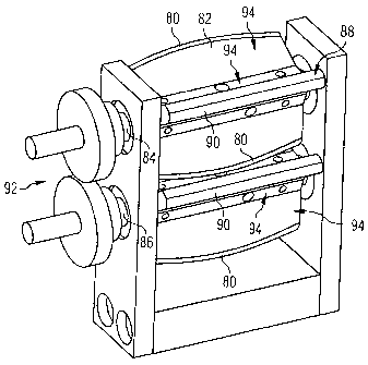
With the spreading installation 34 illustrated in figure 5 the problems
concerning the
quality of the material of rovings or of other fiber filament bundle intended
to be spread,
in that the roving 32 or the fiber filament bundle is newly placed again and
again onto at
least one convexly bent spreading edge. For this purpose the spreading
installation 34
includes at least one convexly curved spreading edge 80 which moves relative
to the
roving 32 or any other fiber filament bundle by at least one component
direction
perpendicular to the longitudinal extension of the roving 32 or any other
fiber filament
bundle, so that the same is placed under tension onto the convexly curved
spreading
edge 80 and thereafter moves away vertically from the roving 32 or the fiber
filament
CA 02680457 2009-09-10
bundle by at least one direction component, so that the fiber filament bundle
becomes
detached from the spreading edge 80.
In its practical configuration the at least one spreading edge 80 is formed on
a radial
projection 82 on a rotary shaft 84.
5
In the preferred construction according to the embodiment illustrated in
figure 5, at least
two edges, at least one of which being constructed as a convexly curved
spreading
edge 80, is movable from opposite directions towards the roving 32 or the
fiber filament
bundle. For this purpose this embodiment provides two rotary shafts 84, 86
having
10 radial projections 82. The rotary shafts 84, 86 rotate in mutually
opposite directions.
In addition to first radial projections 82, where the convexly curved
spreading edges 80
are formed, a preferred embodiment also provides second radial projections 88
terminating in straight edges 90. A spreading device is thus provided in which
at least
15 one convexly curved spreading edge 80 and at least one straight
spreading edge 90
can move from opposite directions towards the roving 32 or the fiber filament
bundle
until the roving 32 or the fiber filament bundle is spread between the edges
80, 90 in the
manner similar to that illustrated in figure 4. The edges 80, 90 can also be
returned in
the opposite direction to relieve the roving 32 or the fiber filament bundle.
In the embodiment according to figure 5, this is particularly easily
implemented in that
several wings 94 forming the radial projections 82, 88 are formed on the
rotary shafts
84, 86 driven in the opposite directions by means of a gear mechanism 92. The
wings
94 substantially extend in the axial direction and the edges 80 or 90 are
formed on their
radially outermost regions. A wing 94 comprising the straight edge 90 is
followed in the
circumferential direction by a wing comprising a convex radially outwardly
curved
spreading edge 80, and this wing is in turn followed by a wing 94 comprising a
straight
edge 90 and so on.
CA 02680457 2009-09-10
16
In a different embodiment, the edges of all wings 94 are constructed as
radially
outwardly curved spreading edges 80. By the arrangement on moving elements
that
move in the opposite directions, in the present embodiment the two rotary
shafts 84, 86,
the fibers are each spread between two oppositely curved spreading edges 80.
In this way the spreading installation 34 is constructed as a so-called wing-
type
spreader which provides for a repeated placement of the rovings 32 on the
spreading
edges 80. Additionally, a finishing layer on the roving 32 or on the fiber
filament bundle
is broken open by the alternating bending operation, and the filaments 100 can
move
independently from each other.
The spreading installation 34 in the spreading device 20 constructed as a wing-
type
spreader is followed in the conveying direction of the rovings 32 by a
loosening
installation 36 which in the present embodiment is constructed as a suction
chamber
according to the so-called Fukui principle. The suction chamber 96 can be of a
type
which is described in US-A-6 032 342. The loosened and pre-spread roving 32 is
drawn
into the suction chamber 96 by a strong laminar air stream 98. Air is caused
to flow
around the individual filaments 100 so that the filaments can relatively
easily slide one
above the other. Further the suction chamber 96 is able to compensate minor
fluctuations in the tension of the rovings 32.
At the production of plastic fibers the bundles of filaments are frequently
freely guided
and passed through eyelets. During this operation, parts of the filaments 100
can twist
around the remainder of the bundle and cause constrictions of the rovings
already at the
time of manufacture. After the reeling of the bundle of filaments on a roving
reel these
defects are hardly visible, because the bundle of filaments is reeled up in a
flat
condition. But after the bundles of filaments have been loosened in the
spreading
installation 34 roving parts running in the transverse direction can be
clearly seen. This
effect can cause gaps and displacements within the roving 32 which negatively
influence the spreading quality.
CA 02680457 2009-09-10
17
To achieve a spreading pattern which is as homogeneous as possible, an
embodiment
of the invention which is not explicitly shown provides for a multistep
spreading
operation, in which the spreading ratio is stepwise increased. For this
purpose a first
spreading installation 34 and a first loosening installation 36 for spreading
the roving 32
to a first width, for example a value between 8 and 16 mm, are provided. This
is
followed by a next step comprising a further spreading installation 34 having
a larger
width and a further loosening installation 36 having greater dimensions than
the first
spreading installation and the first loosening installation, in order to
effect spreading to a
3.0 larger width, for example to a value between 20 and 35 mm.
Thereafter, the roving 32 is present in form of a wide, thin band, i.e. the
fiber band 14.
In the further process, this fiber band 14 is still provided with a small
amount of the
binder material 38.
Theoretically, only three filaments are placed one on top of the other in a
12k roving
which is 30 mm wide and perfectly spread. In this case a diameter of the
filaments 100
of 7 pm and the highest packing density have been assumed. But in reality a
roving 32
still includes spreading defects that may locally cause thicker areas and thus
a higher
number of filament ends.
The impregnation of the thus spread rovings 32 with binder material 38 takes
places in
the binder impregnation device 22, the principle thereof is illustrated in
figure 7. The
basic principle of the binder impregnation device 22 is similar to that of a
powder shaker
of a kind described for example in US-A-3 518 810, US-A-2 489 846, US-A-2 394
657,
US-A-2 057 538 or US-A-2 613 633. Accordingly, this powder shaker comprises a
funnel 102 with a roller 106 having radial raised portions 104 moving past the
exit of the
funnel.
CA 02680457 2009-09-10
18
In the illustrated embodiment said roller 106 is a knurled steel roller which
is transports
the powder with its rough surface. This roller 106 is in turn treated by a
brushing roller
108 removing the powdery binder material 38 from the roller 106 and sprinkling
the
same onto the fiber band 14 passing under the roller 106.
Between the fiber band 14 and the application mechanism a voltage U can be
applied,
so that the powder will electrostatically adhere to the fiber band 14 like in
a powder
coating process.
The transfer roller 106 and the brushing roller 108 are driven by two separate
electric
motors 110 and 112 to enable free adjustment of the sprinkling parameters.
Control
takes place through a control unit 114 which can be a part of the control
device 44.
To avoid the powder from becoming blocked thus causing jamming of machine
parts,
the funnel 102 is not rigidly fixed to the remainder of the binder
impregnation device 22,
but is supported on a holder 116 which allows compensating movements. An
advantage
of the holder 116 is that the funnel 102 can oscillate during operation thus
automatically
shaking the powder downwards. The powder is sprinkled in an amount which can
be
exactly dosed onto the surface of the roving 32 which moves past under the
funnel at a
defined speed of 3 to 6 m/min for example. Excessive powder falls into a
collection
container (not shown) outside of the roving 32 and can be recycled to the
process at a
later time.
Measurements have shown that the amount of binder material applied by
sprinkling is
almost a linear function of the rotating speed of the roller 106.
The binder impregnation device 22 also includes a heating installation 118
serving to fix
the powder particles of the binder material 38 melting at heating temperatures
to the
surface of the filaments 100.
CA 02680457 2009-09-10
19
In the illustrated embodiment the heating installation 118 comprises a heating
line which
is about 100 to 500 mm long. The preferred embodiment of the heating
installation 118
is equipped with radiant heaters, in the present case infrared radiant heaters
120. The
heating power of the heating installation 118 can be precisely set through the
control
unit 114.
The binder particles are slightly melted and adhere to the fiber surface.
Thereafter ¨ as illustrated in figure la ¨ the finished fiber band 14 can be
reeled up on a
special film reel 121 and stored for later use.
In the embodiment illustrated in figure 1, the fiber band 14 provided as a
semi-product
or specially prefabricated is supplied to the cutting installation where it is
cut into the
patches 40, 40', 40" and thereafter laid by the laying device 28.
Figure la shows an embodiment with separate modules 12, 16 and the use of film
reels
121 as an example for intermediate storage. The modules 12, 16 in this form
could also
be situated in different production sites.
Figure 8 illustrates in more detail a second embodiment of the cutting and
laying module
16. In the embodiment according to figure 8 the cutting device 24 comprises a
fiber
cutting tool 122 having a knife system 124 and a counter roller 126 and at
least one or,
as in the present case, several transport rollers 128.
The knife system 124 can be operated in dependence of the rotating speed of
the
counter roller 126 and/or the transport rollers 128, for cutting patches 40 of
a defined
length.
CA 02680457 2009-09-10
In particular, the knife system 124 includes a coupling mechanism (not further
illustrated) coupling a drive unit of the knife system 124 with the drive unit
of the rollers
126, 128.
5 In the illustrated example the knife system 124 is provided with a
cutting cylinder 130
which, as a radial projection, includes at least one and in the present case
several
cutting edges 132. In the illustrated embodiment the cutting cylinder 130 can
be coupled
by a coupling means not further shown to the drive unit of the counter roll
126 in such a
manner that the cutting edges 132 move with the same peripheral speed as the
surface
10 of the counter roller 126.
The cutting device shown in figure 8 and in more detail in figure 9
accordingly
comprises a coupled cutting system 134 in which two pairs of transport rollers
128 and
a rubberized counter roller 126 are driven by means of a motor not further
shown via a
15 central form-locking transmission, for example a toothed belt (not
shown). The transport
rollers 128 feed an endless fiber band ¨ in the present case particularly the
spread fiber
band 14 ¨ and direct the same over the counter roller 126 rotating at the same
speed.
Above the counter roller 126 a cutter bar 136 is in the waiting position.
20 If a cut is to be made, an electromagnetic clutch couples the cutter bar
136 into the
movement of the cutting system. At the contact point the cutter bar 136 and
the counter
roller 126 have the same rotating speed. The material to be cut is broken by a
knife
blade 138. Thereafter the cutter bar 136 is decoupled and stopped for example
by
means of an electromagnetic brake (not shown). The second pair of transport
rollers
128 removes the cuttings.
The coupled cutting system 134 enables the cutting of spread fiber bands
without
distortion. The cutting act or the cutting length can be adjusted computer-
controlled
during operation.
CA 02680457 2009-09-10
21
The brake system (not explicitly shown) provides for a permanent locking of
the cutting
cylinder 130 when the clutch is not active. The coupling and braking
operations take
place via a common changeover relay (not shown) thus excluding failure caused
by
program errors. A sensor system (not further shown), for example an inductive
proximity
switch, registers the position of the knife and provides for a braking effect
on the knives
in a horizontal position. If the connected control unit, for example the
control unit 44,
outputs a cutting command, the cutting cylinder 130 is coupled, accelerates
and makes
a cut. If at this time the cutting cylinder 130 has the same peripheral speed
as the
counter roller 126, as provided in this embodiment, the knife blade 138 is not
bent or
deformed resulting in an endurance of the knife which is much higher than that
of a
simple vertical knife. After the cutting operation the cutting cylinder 130 is
decoupled
and decelerated and held at the same position as at the beginning. The cutting
length is
programmed in control software.
Figure 10 schematically illustrates the flow of the cutting system control. As
shown in
figure 10, the cutting cycle is predetermined in dependence of the feeding
speed of the
cutting system. The minimum cutting length results from the dimension of the
cutting
cylinder 130 and the counter roller 126 and is within a range for example of
the width of
the spread fiber band 14. The maximum cutting length is theoretically
unlimited.
In both illustrated embodiments of the cutting and laying module 16, after
leaving the
cutting device 24, the patches 40, 40', 40" are transferred to the transfer
device 26
which removes the patches 40, 40', 40" from the cutting device 24 at a
transporting
speed which is higher than the conveying speed of the fiber band 14 to the or
in the
cutting device 24. Thus the patches 40, 40', 40" are separated and
sufficiently spaced
from each other. The transfer device 26 comprises a holding system to hold the
patches
40, 40', 40" against the transfer device and a delivery system to deliver the
patches 40,
40', 40" to the laying head 52 of the laying device 28.
CA 02680457 2009-09-10
22
The holding system and the delivery system are here implemented in the form of
a
vacuum band-conveyor 50. A large-volume suction chamber 140 distributes the
suction
force of a vacuum source not further shown, for instance a suction blower,
over the
entire transfer device 26. A band comprising many through pores, for example a
polypropylene band, is passed over a perforated metal sheet 142 covering the
suction
chamber 140.
The transfer device 26 is driven through its coupling to a conveyor unit of
the cutting
device 24. In the illustrated embodiment, the vacuum band-conveyor 50 is
coupled to
the form-locking transmission driving the transport rollers 128 and the
counter roller
126. A corresponding transmission ratio, e.g. a transmission ratio of 1:2,
provides for a
sufficiently large distance between the patches 40, 40', 40". At the end of
the
transferring distance a suction-type blow-off chamber 144 is situated and
driven by a
pneumatic vacuum module. The suction-type blow-off chamber is in operation as
long
as a fiber piece ¨ patch 40 ¨ is passed over the suction-type blow-off chamber
144. As
soon as the laying die is at a predetermined delivery position 146, a blow-off
pulse is
output at the right moment to deliver the patch 40 to the laying head 52.
The laying head 52 attracts the patch 40 by suction, heats and transfers it
with a
predetermined orientation to its predetermined position.
As illustrated in figure 11, during this operation the patches 40, 40', 40"
are placed onto
the preform 30 along predetermined curved paths 148. Pos. 150 indicates
patches laid
with a corresponding orientation along these curved paths 148 and their
overlapping. In
the overlapping zones the patches 40 are fixed to each other by the binder
material 38
heated by the laying head 52.
The cutting device shown in figure 1, in conjunction with a laser 54 (or any
other kind of
beam cutting technique) even allows the production of complicated shapes of
cutting
edges. Figure 12 illustrates a particularly preferred shape of cutting edges,
with the
CA 02680457 2009-09-10
23
cutting edges 152, 154 being curved in a complementary fashion convexly or
concavely
with respect to each other. The oppositely directed cutting edges 152, 154 on
each
patch are curved in a circular arc fashion. Thus the cutting edges 152, 154 of
patches
40, 40', 40" that are arranged one behind the other can be placed very close
to each
other without producing gaps or thickenings even if the patches 40, 40', 40"
are angled.
In this way a lay-up is possible with the fiber pieces constantly tightly
abutting and
having a corresponding fiber orientation also along small curvature radii of
the paths
148. The fixing of the patches 40, 40', 40" can be effected by overlapping
with adjacent
patches or those arranged above or underneath (not shown).
In this manner it is possible to produce even very complicated preforms 42
like those
indicated for example in figure 13. In this example, short fiber pieces
according to the
patchwork type make up a preform 192 for a load path aligned fiber composite
structure
for a window funnel of an aircraft or spacecraft for example. The patches 40,
40', 40"
are oriented corresponding to the load paths.
Concerning the technical process, the illustrated annular shape can be
achieved by a
defined rotatable preform 30 as indicated by the arrows 156 in figure 1.
Now, the laying device 28 and its laying head 52 of the embodiment of the
cutting and
laying module 16 illustrated in more detail in figure 8 will be further
explained with
reference to the figures 14 to 16.
The laying head 52 has the function to pick up a fiber piece or patch 40, 40',
40" and to
transfer the same to the respective next predetermined position 46 on the
preform 30
requiring lay-up of a patch 40, 40', 40". For this purpose the laying had 52
includes a
holding device. While other holding devices are also conceivable, the holding
device in
the illustrated example is constituted by a suction device 158 which makes
picking up
the patches from the transfer device 26 easier.
CA 02680457 2009-09-10
24
Further, it is advantageous to activate the binder material 38 with which the
picked-up
patch 40 is provided, during the transfer by means of the laying head 52. For
this
purpose the laying head 52 includes an activation system for activating the
binder
material 38. The configuration of the activation system depends on the binder
material
which is used. For example, if a binder material is used which is activated by
an
additive, the laying head comprises means for adding the additive. In a
different
embodiment not further illustrated, an instantly activated binder material
such as an
adhesive is supplied only during the transfer of the patch on the laying head.
In this
case the laying head includes means for the addition of binder material. For
use in the
above-described preform manufacturing device employing a thermally activated
binder
material 38, the activation system is constructed as a heating device 160 in
the
illustrated embodiment.
It is further preferable for the laying head 152 being able to lay-up the
patch 40, 40', 40"
even against complicated three-dimensional surface architectures of the
preform. To
this end, the laying head 52 includes a pressing device 162 suitable for
pressing the
transferred patches 40 against different surface architectures. The pressing
device 162
includes in a preferred construction a flexible surface 164 where the patch 40
can be
held by means of a holding device. Further preferably, the flexible surface
164 is formed
on an elastic carrier 166.
Figure 14 shows a cross sectional view of a laying die 168 of the laying head
52
combining the holding device, the activation system and the pressing device.
The laying
die 168 shown in figure 14 accordingly comprises the suction device 158, the
heating
device 160 and the pressing device 162 with the flexible surface 164 on the
elastic
carrier 166.
Figure 15 is a bottom view of the flexible surface 164.
CA 02680457 2009-09-10
If the fiber patch preforming technology (FPP) is applied, the laying die 168
enables
fiber pieces (patches) which are binder-impregnated and cut into defined
geometries
being precisely placed at the intended position according to a laying pattern
(for
example the laying pattern shown in figure 11). The laying die 168 is a
central
5 component of the laying technology and can be used also in other
geometrical
variations. For example, square or roller-shaped laying dies are also
conceivable.
In the concrete embodiment according to figure 14, the laying die 168 is
configured as a
silicone die. The surface adaption of the silicone die is similar to pad
printing, although
10 the present field of application is completely different.
The laying head 168 can quickly and gently pick up and transfer fiber cuttings
to the
defined location through an integrated suction ¨ suction device 158. During
the transfer,
a heater¨ heating device 160¨ integrated in the contact surface ¨flexible
surface 164
15 - heats up the material and thus activates the binder ¨ binder material
38 ¨ on the fiber
cutting. The fiber cutting is pressed onto the surface, with the soft die
material adjusting
to the surface geometry. When the laying die 168 moves away from the surface,
a blow-
off pulse is output, the binder material 38 is cooled and the fiber material
remains where
it has been placed.
The laying die 168 enables the production of fiber patch preforms 42.
In figure 14, the elastic carrier 166 ¨ elastic pressing body ¨ is represented
including an
air distribution 170 which forms a part of the suction device 158. The part of
the suction
device 158 which is not illustrated is provided with the usual pneumatic
sources and
pneumatic controls (not shown). Further, the flexible surface 164 is
represented as an
elastic heating surface 172 including suction and blow-off channels 174.
CA 02680457 2009-09-10
26
The elastic carrier 166 is seated on a coupling plate 4 which is provided with
removable
fixing elements (not shown) for fixing the laying head 168 to a positioning
device 176
(see figure 16).
Further, a thermo element 178 is provided as a control element of the heating
device
160. A highly flexible electrical power line 180 connects the thermo element
178 to the
elastic heating surface 172.
Figure 15 shows a suction surface ¨ flexible surface 164 ¨ including the
suction and
blow-off channels 174.
The use of the laying die 168 as well as further details of the laying device
28 will be
described in the following in context with its use in the preform
manufacturing device 10.
In the fiber patch preforming technology individual fiber patches 40 are
arranged to form
a three-dimensional preform 42, 192. To achieve this, the layout plan is
implemented by
applying a suitable laying technique. The laying device 28 is delivered the
binder-
impregnated and cut fiber patches 40 from the vacuum band-conveyor 50
associated
with the cutting device 24 and places the fiber patches 40 onto a surface, at
a cycle
which is a quick as possible. In the illustrated embodiment the fiber patches
40,40', 40"
are placed onto a surface of the preform 30.
The patches 40, 40', 40" shall be pressed onto the forming surface to produce
a robust
preform 42. The laying die 168 shall be as soft as possible to adjust to a
three-
dimensional surface with uniform force. For this configuration it is further
preferred that
shortly before the placement of the patches a certain amount of heat can be
provided
for activating the binder material 38. For this purpose the flexible surface
164 includes
the heating device 160 which influences the mechanical properties of the die
material as
less as possible. Similar to the vacuum band-conveyor 50, a two-dimensional
fixing of
CA 02680457 2009-09-10
27
the filigree fiber patches 40 is beneficial. For this purpose the flexible
surface 164 also
has a suction function.
The manufacture of the laying die 168 is similar to the manufacture of
printing pads
known from printing engineering. For the manufacture of printing pads a series
of
special silicones are available which are able to resist for a long time the
permanent
alternating mechanical loads. From these silicones a silicone rubber is
selected which
meets the additional requirements caused by the heating device 160 and the
contact
with the binder material 38 as perfectly as possible. Since the laying die 168
has
incorporated a heater, tests have been made with regard to the temperature
stability of
the die material. In this case it is advantageous for the laying die 168 being
able to
resist permanent temperatures of up to 200 C. A softener for the silicone
material is
selected corresponding to these requirements.
For heating the lay-up surface of the laying die 168 various heating devices
160 can be
used, among others also electric heating devices, fluid circuits or hot air.
Concerning the
fabrication technique, the variant comprising an electric heating device 160
is the most
convenient to implement and simultaneously offers the possibility of a high
heating
power and an exact temperature setting.
To not influence the flexibility of the carrier 166, the electric power lines
180 are
advantageously formed by means of carbon fiber yarn. The high flexibility of
such a fiber
yarn prevents the flexible surface 164 from becoming stiff. Also, such a fiber
is able to
stand several 100,000 load cycles.
The thermal conductivity of the elastic carrier 166 can be increased by
admixing
thermally conductive material to the silicone.
For instance, with a moiety of the thermally conductive material of about 10-
30 percent
by weight the thermal conductivity of the flexible surface is sufficiently
high, so that a
CA 02680457 2009-09-10
28
heating element of the heating device 160 and the flexible surface 164 can be
kept at
almost the same temperature.
The suction and blow-off channels 174 are integrated in the flexible surface
164 of the
laying die 168 and join each other inside the laying die 168 through a chamber
182. In
the chamber 168 an absorbing suction fleece (not shown) is inserted preventing
collapsing when subject to the pressure load of the laying die 168.
To avoid electrostatic charging, the flexible surface 164 is advantageously
made of a
flexible material having antistatic properties.
The mechanical lay-up system of the laying device 28 will still be explained
in the
following with reference to figure 16.
The mechanical lay-up system 184 illustrated in figure 16 serves to move the
laying die
168, in order to transfer fiber patches 40 from the cutting device 24 to the
predefined
position 46. The mechanical lay-up system 184 allows a rapid laying cycle and
an
adjustable lay-up angle.
As explained above, the patch 40 is delivered in contactless fashion from the
vacuum
band-conveyor 50 to the laying die 168. For this purpose the control device 44
outputs a
blow-off pulse of the suction/blow-off chamber 144 of the vacuum band-conveyor
50
after a preset delay time and in dependence of the cutting command. The patch
40 is
delivered via an air path of a few millimeters (about 0.5 ¨ 10 mm) to the
aspiring laying
die 168. Thereafter, the movement cycle of the mechanical lay-up system 184
commences.
The mechanical lay-up system 184 comprises a translational drive for the
transfer of the
laying die 168 from the pick-up position to a position above the predetermined
position.
In the illustrated embodiment of the mechanical lay-up system 184 the first
drive unit is
CA 02680457 2009-09-10
29
constituted by a horizontal pneumatic cylinder 186. This horizontal pneumatic
cylinder
186 is adapted to move the laying die 168 from its pick-up position to the
placement
position. A second drive unit constituted by a vertical pneumatic cylinder 188
presses
the laying die 168 onto the surface, preferably at a pressure that can be
adjusted.
During the displacement, the surface of the die is permanently kept at an
adjustable
temperature, so that the binder can activate its adhesiveness. As soon as the
patch 40
contacts the surface the binder material 38 cools down and becomes solid.
Then, under
the control of the control device 44, the blow-off pulse in the suction device
of the laying
die 168 is output causing the laying die to move away and thereafter return to
its initial
position. Here the separating properties of the silicone are beneficial,
because there is
not any binder material 38 remaining on the die.
By means of a third drive unit, which in the illustrated embodiment is
constituted by a
stepping motor 190 including a spline shaft system 191, the laying die 168 can
be
rotated. Accordingly it is possible to even produce traces of inclined patches
40 without
requiring the entire laying head (e.g. the laying die 168 including the
mechanical lay-up
system) being rotated.
To achieve an economic laying process a very high cycle time of more than two
laying
operations per second has been planned. Five laying operations per second or
even
more are performed for example. With a patch length of 60 mm and using a 12k
roving,
a fiber throughput of theoretically 14.4 g/min is achieved. If it is intended
for instance to
cover one square meter with fiber patches 40 having the thickness of a biaxial
laying
(approximately 500 g/m2), the preform manufacturing device 10 would require 35
minutes. Shorter times are possible by using several laying devices 28 in
conjunction
with several robots working together on one surface.
Because of the relatively low achievable speeds, the FPP technique in its
currently
presented form is still mainly applied for the reinforcement of other types of
preforms
CA 02680457 2009-09-10
and for thin-walled and complex components, for example the reinforcement of
the rims
of holes in multi-axial layings or fabrics. A window funnel, the preform 192
thereof is
shown in figure 13, could also be produced with a very thin wall and with a
defined fiber
layer.
5
Certain types of preforms require lesser degrees of freedom in a FPP system ¨
preform
manufacturing device 10. If it is only reinforcement profiles that are to be
produced, the
individual modules could be simplified and combined into one production line.
Modules
which are not required could be omitted. Alternatively, the device could be
separated in
10 several modules including intermediate storage of the semi-finished
material.
This would help to reduce system costs and to increase productivity.
CA 02680457 2009-09-10
31
List of reference numbers
preform manufacturing device
12 preparation module
5 14 fiber strand
16 cutting and laying module
18 pay-off device
spreading device
22 binder impregnation device
10 24 cutting device
26 transfer device
28 laying device
preform
32 roving
15 34 spreading installation
36 loosening installation
38 binder material
40, 40', 40" patch (section of a fiber band; fiber band pieces)
42 preform
20 44 control device
46 predefined position
48 fiber cutting system
50 vacuum band-conveyor
52 laying head
25 54 laser
56 supply reel
58 support
60 linear guideway
62 carriage
30 64 drive screw
CA 02680457 2009-09-10
32
66 motor
68 sensor
70 position
72 photodiode
74 flat band
75 little reel
76 bent rod
78 straight rod
80 spreading edge
82 first radial projection
84 rotary shaft
86 rotary shaft
88 second radial projection
90 straight edge
92 gear mechanism
94 wing
96 suction chamber
98 laminar air stream
100 filaments
102 funnel
104 radial raised portions
106 roller
108 brushing roller
110 electric motor
112 electric motor
114 control device
116 holder
118 heating device
120 infrared heating radiator
122 fiber cutting system
CA 02680457 2009-09-10
,
, =
,
33
124 knife system
126 counter roller
128 transport roller
130 cutting cylinder
s 132 cutting edges
134 coupled cutting system
136 cutter bar
138 cutting blade
140 suction chamber
142 perforated metal sheet
144 suction/blow-off chamber
146 delivery position
148 curved paths
150 overlapping patches
152 cutting edge
154 cutting edge
156 mobility of the preform ¨ multidimensional
158 suction device
160 heating device
162 pressing device
164 flexible surface
166 elastic carrier
168 laying die
170 air distribution
172 elastic heating surface
174 suction and blow-off channels
175 coupling plate
176 positioning device
178 thermal element
180 electric power line
CA 02680457 2009-09-10
34
182 chamber
184 mechanical lay-up system
186 horizontal pneumatic cylinder (first drive unit)
188 vertical pneumatic cylinder (second drive unit)
190 stepping motor (third drive unit)
191 spline shaft system
192 window funnel preform