Note: Descriptions are shown in the official language in which they were submitted.
CA 02680515 2009-09-10
WO 2008/110012 PCT/CA2008/000499
1
Method for Purifying Silicon
J!rjolily of Invention
This non provisional application claims the benefit of priority to U.S.
Provisional
Patent Application Serial No. 60/894,587, filed March 13, 2007 which is herein
incorporated by reference.
Backgromd ofthe Invention
Solar cells are currently utilized as an energy source by converting sunlight
to
electrical energy. Silicon is used ahnost exclusively as the semiconductor
material in
such photovoltaic cells. A significant limitation currently on the use of
solar cells has to
do with the cost of purifying silicon to solar grade. In view of current
energy demands
and supply limitations, there is an enormous need for a more cost eff-xcient
way of
purifying metallurgi.cal grade silicon (or any other silicon having higher
impurities than
solar grade) to solar grade siiieon. US I'atent No. 4,312,848 "Boron Removal
in Silicon
Purification" discloses the removal of boron from silicon through treatment of
molten
aluminurn-silicon with a metal selected from the group consisting of titanium,
vanadium
or zirconie2m and gas injection. US Patent No. 4,312,849 "Phosphorous Removal
in
Silicon Purification" discloses the removal of phosphorous by bubbling a
chlorine
containing gas tbxough the molten alurninum-silicon bath.
Biief Description of the Figurse
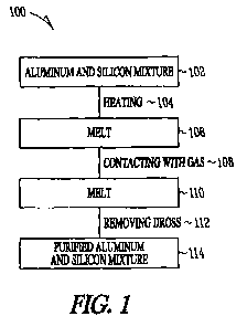
FIG 1 illustrates a block flow diagram of an exemplary process of the present
invention, according to some embodiments.
Detailed Descri2tion of the Ynvention
Reference will now be made in detail to certain claims of the invention,
examples
of which are illustrated in the aecompanying structures and formulas. While
the
invention will be described in cozjxnction with the enumerated claims, it will
be
understood that they are not intended to limit the invention to those claims.
On the
CA 02680515 2009-09-10
WO 2008/110012 PCT/CA2008/000499
2
Attorneybocktt No. SLWX 2552.002'tivOt
contrary, the invention is intended to cover aII alternatives, modifications,
and
equivalents, whicb may be included with'sn the scope of the present invention
as defined
by the claims.
References in the specification to "one cinbodiment", "an embodimcnt", "an
example embodiment", etc., indicate that the embodiment desaibed may include a
particular feature, structure, or characteristic, but every embodiment may not
necessarily
include the particular feature, structure, or c}aalaeteristic. Moreover, such
phrases are not
necessarily refcrring to the same cmbodiment. Further, whcn a particular
feature,
structure, or characteristic is described in connection with an embodiment, it
is submitted
that it is within the knowledge of one slalled in the art to affect such
feature, structure, or
characteristic in connection with other embodiments whcthcr or not explicitly
described.
Definitions
Unless stated otherwise, the following terms and phrases as used herein are
intended to have the following meanings:
In the methods of manufacturing described herein, the steps can be caried out
in
any order without departing from the principles of the invention, except when
a temporal
or operational sequence is explicitly reCited. Recitation in a claim to the
effect that first a
step is performecl, then several other steps are subsequently performed, shall
be taken to
mean that the first step is performed before any of the other steps, but the
other steps can
be performed in any suitable sequence, unless a sequence is fiuther reoited
within the
other steps. For example, claim elements that recite "Step A, Step B, Step C,
Step D, and
Step E" shall be construed to mean step A is carried out first, step E is
canied out last,
and stcps B, C, and 7) can be carried out in any sequence between steps A and
E, and. that
the sequence still falls within the literal scope of the claimed process.
Furthenmare,
specified steps can be carried out concurrently unless explicit claim language
recites that
they be carried out separately. For example, a cl.aimed step of doing X and a
claimed
step of doing Y can be conducted simultaneously within a single operation, and
the
rasalting process will fa11 within the literal scope of the elaimod proccss.
As used herein, "7nultiple" refers to two or more, e.g., 2, 3, 4 or 5.
CA 02680515 2009-09-10
WO 2008/110012 PCT/CA2008/000499
3
Attorney Docket No. SLWK 2552.002W01
As used herein, `purifying" refers to the physical separation of a chemicaI
substance of interest from foreign or contaminating substances.
As used herein, "contacting" refers to the act of touching, malQng contact, or
of
immodiato proximity.
As used herein, "decanting" or "decantation" includes pouring off a fluid,
leaving
a sediment or precipitate, thereby separating the fluid from the sediment or
precipitate.
As used herein, "separating" refers to the process of removing a substance
from
another (e.g., removing a solid or a liquid from a mixture). The process can
employ any
technique known to those of slcill in the art, e.g., decanting the mixture,
sldmming one or
more liquids from the mixture, centrifLiging the mixture, filtering the solids
from the
mixture, or a combination thereof.
As used herein, "filtering" refers to the process of removing solids from a
mixture
by passing the liquid through a filter, thereby suspending the solids on the
filter. Filtering
may include a mechanical method to separate solids fi+om liquids by passing
the feed
stream through a porous sheet such as a ceramic or metal membrane, which
retains thc
solids and allows the liquid to pass through. This can be accomplished by
gravity,
pressure or vacuum (suction). The filtering effectively separates tlxe
sediment or
precipitate from the liquid.
As used herein, "skimtni.ng" refers to the process of removing one or more
liquids, sol.ids of combination there of from a mixture, wherein the one or
more liquids
are floating on top of the mi7cture.
As used herein, "agitating" refers to the process of putting a mixture into
motion
with a turbulent force. Suitable methods of agitating include, e.g., stirring,
mixing, and
shaldng.
As used herein, "precipita,ting" refers to the process of causing a solid
substance
(e.g., crystals) to be separated from a solution. The precipitating can
include, e.g.,
crystallzing.
As used herein, "silicon" refers to the chcmical element that has the
symbol Si and atomic number 14. Measured by mass, silicon malces up 25.7% of
the
Earkh's crust and is the second most abundant element on Earth, a$er oxygea
Pure
silic,on crystals are only occasionally found in nature; they can be found as
inclusions
CA 02680515 2009-09-10
WO 2008/110012 PCT/CA2008/000499
4
Atoorney Docket No. Sx.'17J'K 2552.002W01
with gold and in volcanic exhalations. Silicon is usually found in the form of
silicon
dioxide (also known as silica), and silicate. Silica oecurs in minerals
consisting of
(practically) ptzre silicon dioxide in different crystalline forms (quartz,
chalcedony, opal).
Sand, amethyst, agate, quartz, rock crystal, flint, jasper, and opal are some
of the forms in
wliich silicon dioxide appears (they are known as "lithogenic", as opposed to
"biogenic",
silicas). Silicon also occurs as silicates (various minerals containing
silicon, oxygen and
one or another metal), for example feldspar. These minerals occur in clay,
sand and
various types of rock such as granite and sandstone. Asbestos, feldspar, clay,
hornblende,
and mica are a fcw of the many silicate minerals. Silicon is a principal
component of
aerolites, which are a class ometeoroids, and also is a component of
tektites, vcahic.h are a
natural form of glass.
As used herein, "metallurgical grade silicon" (MG) refers to relatively pure
(e.g.,
at least about 96.0 wt.%) silicon.
As used herein, `4nolten" refers to a substance that is melted, wherein
melting is
the process of heating a solid substance to a point (called the melting point)
nv'here it turns
into a liquid.
As used herein, "solvent metal" refers to one or more metals, or an alloy
thereof,
which upon heating, can effectivoly dissolve silicon, resulting in a molten
liquid.
Suitable exemplary solvent metals include, e.g., copper, tin, zinc, antimony,
silver,
bismuth, alunainum, cadmium, gallium, indium, magnesium, lead, an alloy
thereof, and
combinations thereof.
As used herein, an "alloy" refers to a homogeneous mixture of two or more
elements, at least one of which is a metal, and where the resulfmg material
has metaliic
properties. The resulting metallic substance usually has diferent properties
(sometimes
significantly different) from those of its components.
As used herein, "liquidus" refers to a line on a phase diagram above which a
given substance is stable in the liquid phase. Most commonly, this line
represents a
transition temperature. The liquidus may be a straight line, or it may be
curved,
depending upon the substance. The liquidus is most often applied to binary
systems such
as solid solutions, including metal alloys. The liquidus may be contrasted to
the solidus.
The liquidus and solidus do not necessarily align or overlap; if a gap exists
between the
CA 02680515 2009-09-10
WO 2008/110012 PCT/CA2008/000499
Attorney DoCkdc No_ SLWK 2552.002W01
liquidus and solidus, then within that gap, the substance is not stable as
either a liquid or
a solid.
As used herein, "solidus" refers to a line on a phase diagram below which a
given
substance is stable in the solid phase. Most commonly, this line represents a
transition
temperature. The solidus may be a straight line, or it may be curved,
depending upon the
substance. The solidus is most often applied to binary systems such as solid
solutions,
including metal alloys. The solidus may be oontrasted to the liquidus. The
solidus and
liquidus do not necessarily align or overlap. If a gap exists between the
solidus and
liquidus, then within that gap, the substance is not stable as either a solid
or a].iquid; such
is the case, for example, with the aluminum-silicon system.
As used herein "evolve" or "evolwc a gas" refers to the process in which a
liquid
or solid will undergo a chemical reaction or decomposition to release a gas
under certain
conditions (typically high temperature).
As used herein, "dross" refers to a mass of solid impurities floating on a
molten
metal bath It appears usually on the melting of low melting point met,als or
alloys such
as tin, lead, zinc or aluminum, or by oxidation of the metal(s). It can be
removed, e.g., by
slamming it off the surface. With tin snd lead, the dross can also be removed
by adding
sodium hydroxido pellets, which dissolvo the oxides and form a slag. With
other metals,
salt fluxes can be added to separate the dross. Dross is distinguished from
slag, which is
a(visoous) liquid floating on the alloy, by being solid.
As used herein, "slag" refers to by-product of smelting ore to purify metals.
They
can be considered to be a mixture of metal oxides; however, they can con,tain
metal
sulphides and metal atoms in the elemental form. Slags are generally used as a
waste
removal mechanism in metal smelting. In nature, the ores of inetals such. as
iron, copper,
lead, aluaninum, and other metals are found in impure states, often oxidized
and mixed in
with silicates of other metals. During smelting, when the ore is exposed to
high
temperatures, these impurities are separated from the molten metal and can be
removed.
Ttie collection of compounds that is removed is the slag.
As used hcrcin, "inert gas" refers to any gas, or combination of gases, that
is not
reactive under normal circutnstances. Unlike the noble gases, inert gases are
not
necassarily elemental and are often molecular gases. Like the noble gases, the
tendency
CA 02680515 2009-09-10
WO 2008/110012 PCT/CA2008/000499
6
Attorney 17oclret No. SLWK 2552.002'W'Q 1
for non-reactivity is due to the valence, the outermost electron shell, being
complete in a11
the inert gases. Exemplary inert gases include, e.g., helium (He), neon (Ne),
argon (Ar)
and nitrogen (N2).
As used herein, "rotary degasser" refers to an apparatus for removing
impurities
from molten metal that includes a degasser shaft, an impeller block and a
coupling. The
shaft is preferably hollow to allow for the passage of gas therethrough. The
impeller
block is connected to the degasser shaft, is typically formed of heat
resistant material and
has at least one metal-transfer recess, which displaces molten metal when the
bloalc is
rotated. The block preferably includes at least one gas inlet in communication
with the
hollow portion of the degasser shaft and a gas-release opening formed in each
metal-
transfer recess. Each gas-release opcning communicates with one of the gas
inlets. The
coupling connects the degasser shaft to a drive shaft and is formed of two or
more
coupling members.
As used herein, "vortex" refers to a spinning, often turbulent, flow (or any
spiral
motion) with closed streamlines. The shape of media or mass swirling rapidly
around a
center forms a vortex. It flows in a circular motion.
As used herein, the tenn "solar panel" refers to a photovoltaic module which
is
an a,ssesnbly of solar cells used to generate electricity. In all cases, the
panels are
typically flat, and are available in various heights and widths. An array is
an assembly of
solar-thermal panels or photovoltaic (PV) modules; the panels can be connected
either in
parallel or series depending upon the design objective. Solar panels typically
find use in
residential, commercial, institutional, and light industrial applications.
The present invention provides a process that can be used as part of a
relatively
low cost method oÃpurifying silicon aluminium mixtures by removing one or more
of
phosphorus and boron. The purified silicon aluminum mixtures may be fiuther
pmcessed
to remove aluminum and the purified silicon may be used in the manufacture
solar cells,
for example. The methods of the embodiments of the pment invention relate to
boron
and phosphorus removal from silicon ahu*+++++m*+n mixtures in less steps and
less cost than
traditional processes. For example, in one step of the method, the melt may be
optionally
cooled before removing the dross. In addition, the dross may be optionally re-
heated
prior to removal for more effective removal of boron and phosphorus while
maintaining
CA 02680515 2009-09-10
WO 2008/110012 PCT/CA2008/000499
7
Attorney Docket No. SLWK 2552,002WO1
higher silicon and/or silicon aluminum mixture recovery yields. The removal of
dwss
substantially prevents ` back-contamination" of impurities in the melt.
Injection of chlorine gas directly into molten silicon has limitations due to
the
high temperature required to melt silicon (approximately 1410 C). Additions of
aluminium lower the melting temperature making lower temperature gas injection
posstble. This helps to minixnize contamination from the equipment and fumace
and
prevent ccrtain gascs from forming at higher temperature`a. Compounds formed
with the
chlorine or oxygen gas arc also liquid or solid at the lower temperahxres
instead of gases.
The present invention can be carried out on a large commercial scale (e.g., at
least about
70 tons per year).
Referring to FIG. 1, a block flow diagram 100 of an exemplary process of
purifying silicon is shown, according to some embodiments. A mixture 102 of
aluminum
and silicon may be heated 104 to form a melt 106. The rnelt 106 may be
optionally
cooled to a temperature above the solidus temperature, providing a cooled
melt. The melt
106 may be contacted 108 with a gas comprising at least onc of clilorine and
oxygen.
Dross may be removed 112 from the melt 110 in contact with a gas. The process
removes at least one of boron or phosphorus from the aluminum-silicon mixture
to
provide purified aluminum-silicon mixture 114, Optionally, the dross may be
heated
above the liquidus of the melt prior to removal 112.
An aluminuni and silicon mixture 102 may be heated 104 to provide a melt 106.
The heating 104 may be at a temperature close to, at or above the liquidus
temperature of
the mixture to provide a melt 106. The mclt 106 may be substantially liquid, a
slush or
completely liquid, for example. Heating 104 may be within about I00 C, about
50 C or
about 10 C of the liquidus temperature, for example. The heating 104 may be
at or above
thc liquidus temperature of the mixture 102, sufficient to provide a melt 106.
The mixture 102 may also include ealcium. Calcium may reduce the amount of
aluminum chloride (A1C13) fumes and may also help to reduce the phosphorus
levels
during gas contacting (e.g., injecting). The components other than silicon and
conta**>inA* ts in the mixturc, act as a solvent for the silicon in the
mixture 102. In
addition to aluminum, one or more additional solvent metals may be present.
For
example, about 25% to about 70% silicon may be present and about 30% to about
75%
CA 02680515 2009-09-10
WO 2008/110012 PCT/CA2008/000499
8
Attorney Doclwx No. SLWK 2552,002W01
aluminum. About 30% to about 60% or about 40% to about 50 /a silicon may also
be
present in the mixture. About 40% to about 65% or about 45% to about 55%
aluminum
may also be present, for example, In addition, aluminum-silicon mixtures may
be
combined with calcium-aluminum miatures, titanium-aluminum mixtures, vanadium-
aluminum mixtures, zirconium-aluminum mixtures, chromium-aluminum mixtures,
hafnium-aluminum mixtures silicon dioxide, copper and sodium chloride and
other salts,
or any combination thereofy for example.
When the silicon to be purified is about 99.0 wt.% purity, aluminum may be
commercial grade, e.g. 99.5 wt.% aluminuxn. Aluminum having 99.9 wt.% purity
introduces less impurities to the system. l-Tigher purity metallurgical grade
silicon andlor
aluminum may give better results but may increase the cost to achieve sueh
higher
purities. Further, it will be understood that aluminum-silicon type alloys
containing large
amounts of silicon may be used without adversely affeoting the quality of
purified silicon
obtained from the process. However, other materials which would be regarded as
impurities with respect to silicon should be controlled rather closely in
certain instances
in order that high purity silicon may be obtained econoxnically:
Substantially all silicon crystals may be dissolved to get any phosphorus and
boron into the melt 106 and out of the silicon crystals. An induction furnace,
gas furnace
or electric resistance furnace may be used. Crraphite, silicon carbide,
silicon carbide-
alumina, alumina, fused silica, quartz or silicon nitride (Si3N4) material may
be utilized
for tools and rotary impeller or a combination of these materials. Non-
phosphate bonded
refractory may be used for the furnace lining or crucible. Approximately 25-70
wt%
silicon may be present in the rnixture 102 or alloy, before adding additional
components.
Lower concentrations of silicon may detxease the process yield and higher
concentrations
may cause increased dross and silicon loss during gas injection.
Aluminum with low impurity limits for iron, manganesc, titanium etc. may be
utilized. The phosphorus and boron levels may not need to be minirnized, but
higher
levels may increase the time and cost to complete the process. One suggested
alloy is
P0404 or P 1020 primary aluominum alloy which has low impurity limits and a
reasonable
cost.
CA 02680515 2009-09-10
WO 2008/110012 PCT/CA2008/000499
9
Attorney Docket No. SLVVIC 2552.002W01
Metallurgical silicon may be used with a low phosphorus and boron content. It
is
preferable that phosphorus and boron levels be mininiized, as higher levels
may increase
the time and cost to complete the process. Metallurgical silicon may be used
with about
14-135 ppm wt%, aboul 14-75 ppm wt% or about 14-30 ppm wt% phosphorus and
about
4-50 ppm wt%, about 4-35 ppm wt'/o or about 4-15 ppm wt% boron. Aluminum
(e.g.,
1000 series) may be used with about 0.3-7 ppm wt%, about 0.5-5 ppm wt% or
about 1-
3.5 ppm wt% phosphorus or boron. Also, aluminum concentration may he varied.
Heating 104 may occur in a molten bath, sufficient to provide a molten liquid
or
melt 106. Heating 104 may include increasing the temperature of the bath above
about
750 C, about 890 C or about 1200 C, for example. If chlorine gas is not
utilized to help
lower thc melt temperatures, higher tonaperatures may be needed to heat the
mixture and
subsequently contact with oxygen, for example. The temperature of the bath may
be
optionally lowered down to approximately 725-950 C, approximately 750-900 C
or
approximately 600-1000 C after the bath has been heated. The melt may be
optionally
cooled to a temperature between the solidus and liquidus tanpcrature of the
melt 106, for
example. The temperature to lower the bath to may be dependent on the
composition of
the original mixture. The bath may be well mixed during the cool down so that
the
silicon crystals do not form on the walls of the furnac:e or the surface of
the bath
Any mixing, such as from a rotating impellor or ftom induction currenats, may
form a vortex, which may introduce oxygen in order to create dross high in
boron.
Contacting 108 the mixture with oxygen may be by mixing to fonn a vortex, for
example.
The formation of a vortex may also create morc dross and may contaminate the
melt 106
when boron or phosphorous diflbse out of the dross back and Into the bath. The
bath may
be optionally cooled over approximately one hour or longer at a rate of about
30-
1 S0 C/hour. Optionally cooling the melt 106 before contacting with gas may
help to
improve the process by pushing the impurities out of the forming silicon
crystals into the
liquid part of the melt 106, where they can be removed. Mixing during oooling
prevents
the sides of the fuanace from building up crystals and also helps to improve
the purity of
the forrniing crystals. As the orystals grow, the boundary layer between the
growing
silicon crystal and molten mixture becomes depleted in silicon. The mixing
helps to
CA 02680515 2009-09-10
WO 2008/110012 PCT/CA2008/000499
Attornoy Dockct No. SLWK 2552.002W01
prevent the depletion of silicon in this boundary layer, thereby improving the
purity of
the crystals.
A mixture of about 3-20%, about 4-15%, about 5-12% chlorine gas or oxygen and
about 80-97 %, about 84-93% or about 87-90% inert gas (e.g., argon, nitrogen
or a
combination thereof) may be contacted 108 with the melt 106, such as injecting
through a
rotary degassing device. A mixture of about 16 wt.% chlorine gas and about 84
wt,or6 of
an inert gas may also be utilized. Chlorine gas, oxygen gas or a combination
thereof may
provide from about 3% to about 100%, about 5% to about 90%, about 15% to about
75%
or about 20% to about 70% of a gas mixture. The remaining gas or gases may be
inert
gases, for example. After contacting 108 the melt 106 with chlorine or oxygen,
the melt
110 may be furthcr contactod with hydrogen, one or more inert gases or a
combination
thereo~ for example. Sources of chlorine include gaseous chl.orin.e (C1Z),
carbonyl
chloride (COC12), hydrochloric acid (HC1) and carbon torachloride (CC14), for
example.
A solid blowing agent that ev'olves a gas or gas mixture may also be contacted
108 with
the melt 110. Oxygen may also contact the melt 106 without contact from
chlorine, such
as by mixing. A higher concentration up to 100% chlorine gas may also be used.
Hydrogen or hydroehloric acid gas, hydrochloric acid and/or water vapour or a
combination of these gases may also be used. Af4er contacting with chlorine or
oxygen,
the melt may be contacted with argon or nitrogeen for about 15 minutes, about
30 minutes
or for an hour or more.
. In one embodiment, the molten liquid may contact the gas employing an
apparatus configured to release a gas witlhin the molten bath, such as a
rotary degasser. A
rotary degasser can effectively introduce the gas or gas mixture into the
molten liquid.
Additionally, a rotary degasser may effectively agitate (e.g., stir) the
molten liquid while
the gas is introduced into the molten liquid, creating relatively small
bubbles. For
example, the bubbles may be about 1-10 mm, about 2-8 mm or about 3-5 mm in
diameter, on average.
If utilized, a rotary degasser may spin fast enough to inject fme bubbles into
the
melt. The degasser may operate at about 300-400 revolutions per mintrte
(RPIVi),
depending on the bath size and mixer desigr.t. The smaller the bubbles, the
faster the
reaction kinetics and the more efficient the phosphoras, boron and other
impurity
CA 02680515 2009-09-10
WO 2008/110012 PCT/CA2008/000499
11
Attorney riocket No. S1.wYC 2$52,002'W41
removal. Gas bubbles may be about 1-10 mm, about 2-8 mm or about 3-5 mm in
diameter on avmge, for etrample. A graphite impeller and standard refractory
used with
aluminum (e.g., alumina refractory with low phosphorus) can be used without
significant
phosphorus contAmi*+ntion problems from the impeller and furnace wa11s. During
the gas
c,ontacting, the rate of gas injection may be controlled to prevent excess gas
usage. Por
example, a flow rate of about o.5-91/min, about 2-7 I/min, or about 3-5 Umin
may be
utilized in various size fitrnaces. In fnrnaceg of differing sizes, flow rate
ranges may be
adjusted accordingly (e.g, a flow rate of about 61Jmin in a 9301b and about 3-
5 Um in a
2501b furnace). Chlorine gas can be smelled and white aluminum chloride
(A1C13) smoke
can be seen when the gas is being injeoted too quiclrly: A fume hood may be
preferably
used to suck out any black or brdwwq, powdcr that fonals around the impeller,
this shaft
minimizing dross sitting on the surface of the bath and helps prevent the
pllosphorus and
boron from difl'using back into the bath from the dross. The excess dross that
forms may
be removed without removing the aluminum-silioon or silicon crystals in the
melt. The
inixer may be used to xuix the dross into the bath to speed up the reaction
rates witlwut
generating too much dross, but care must be taken not to contaminate the bath.
The chlorine gas may react with any magnesium, aluminum, strontium, sodium,
calcium and/or other alkali metals or alkali earth metals in the melt to form
salts. These
salts may help to wet impurities in the melt that have formed compounds. It is
believed
that as the gas bubbles rise through the melt, the impurities such as Ca3P4,
zirconium
boride (ZrBz), perboric acid (I:TBO3), titaniure diboride (TiB2), 7rAl3+TiB2
agglomerates
or eaiciutn phosphatc (Ca3(PO4)Z) stick to the surface of thes bubble and are
dragged to the
surface of the melt where they can be removed with the dross. Magnesium,
strontium,
sodium and calcium concentrations are lowered in the bath from the formation
of sodium
chloride (NaC1), magnesium chloride (MgCl)7 calcium chlori.de (CaCIZ) and
strontium
chloride (SrC12) salts which float on the surface of the bath and may be
removed with the
dross as are other alkali metals or alkali earth metals salts formed with
chlorides.
Potassium chloride-magnesium chloride (KC1-MgC1) salts may also be used to
lower the phosphorus levels in the melt, but this may result in increascd
levels of
magnesium in the melt, which may then be removed by chlorine injeotion into
the molten
bath. Using salts followed by a chlorine gas mixture can speed up the process
by
CA 02680515 2009-09-10
WO 2008/110012 PCT/CA2008/000499
12
Auormey Doolact No. SLWK 2552.002W01
lowering the phosphorus quickly to lower levels. Other examples of such salts
include
sodium chloride (NaCI), sodium fluoride (NaF), sodium bicarbonate (N'a]HCO3),
sodium
carbonate (Na2CO3), sodium oxide (Na20) and calcium fluoride (CaF2) salts. It
is
possible to use higher levels of chlorine gas in the gas mixture, speeding up
the process,
but this may cause increased emissions that may require using increased
pollution control
equipment
After the phosphorus and boron have bccn lowered to an acceptable level, the
melt 110 may be optionally heated up close to or above the liquidus
t,empcrature and the
dross removed 112. Removing 112 the dross at temperatures much lower than the
liquidus may cause some removal of the silicon crystals as dross, since a
dross strainer
may remove dross and silicon crystals which both float near or on the surface
of the bath.
The cooled dross can be screened to separate the metal chucks, oxide porwwd.er
and silicon
crystals. The dross may subsequently be removed from the molten liquid, for
example,
using a skimmer. Typically, the dross may be a gray powder, semi-solid dross
with
oxides mixed with a mother liquor or black powder, located on the surface of
the molten
liquid. In one embodiment, the rotary degasser can create a vortex of the
molten liquid,
whic,h can effectively mix the dross in the molten liquid. In such an
embodiment, the
vortex can contact oxygen to provide additional dross. Thc formed silicon
crystals in the
dross may also have low impurities. Phosphorous maybe reduced to about 0.1-20
ppm
wt%, about 2-15 ppm wt% or below about 5 pprn wt%. Boron may be reduced to
about
0.1-10 ppm wt%, about 0.5-5 ppm wt% or about 1-3.5 ppm wt%, for example_
Strontium
and calcium may be reduced to about 0.1-5 ppm wt%, about 0.5-3.5 ppm wt% or
about 1-
2.5 ppm wt% and magnesium may be reduced to below 10 ppm wt%, below about 8
ppm
wt% or below about 5 ppm wt%, for example.
The proccss according to the present invention removes the boron to
unexpectedly
low levels for two reasons. It is believed the boron forms TiBz inclusions
which get
dragged to the surface of the bath. These inclusions are wet by the chlorine
containing
bubbles and by oxygen from the air that seems to react with the boron in the
melt forming
oxides with the boron. This means that the boron may be removed in an aluminum-
silicon-calcium or aluminum-silicon melt by introducing a vortex which creates
drosses
rich in boron or by injecting gases oomprising at least one of chlorine and
oxygen directly
CA 02680515 2009-09-10
WO 2008/110012 PCT/CA2008/000499
13
Attorno'y Dockct No. SLWK 2552.002W01
into the aluminum-silicon-calcium or aluaminum-silicon melt. Higher
temperatures may
accelerate the formation of dross and boron removal so this process may be
performed at
temperatures around 1000-1300 C without chlorine injection. Either with or
without
chlorine injection the process can remove boron from the melt down to about
0.1-10 ppm
wt'/o, about 0.5-5 ppm wt% or abotit 1-3.5 ppm wt%.
The process may also be used to remove calcium, lithium, magnesium, strontium,
alumiutum, titanium and other elements with a higher affnity for oxygen or
chlorine than
silicon. This means that injection of an oxidizing gas (C02, 02, etc.) or
mixing to cause
oxygen in the air to react with the aluminum silicon melt can be used to
remove the
aluminum solvent from the aluminum silicon mixtures as aluminum oxide or
dross. The
process of the present invention, or any step thereof, may be repeated ono or
more times
to fiuther remove boron, phosphorus or both. The process, or any step thereof,
may be
repeated using different equipment to reduce contamination, such as by using a
second
and subsequent fumaces for heating. The process may also be carnied out on a
eommcrcial scale (c.g., using about 10001bs (453.592 kg) to about 40,000lbs
(18143.694
kg)) ofmixture.
F~x=vlss
EIA=le
A 2101b. mixture of 30% silicon - 70 wt'% aluminum, made of low grade
metallurgical
silicon with approximately 120 ppm wt% phosphorus and 30 ppm wt'/o boron was
mixed
with scrap 1000 sexies electrical conducting ahuninum wi:ro resulting in a
aluminum-
silicon mixture with ] 9 ppm wt% boron and 90 ppm wt*/o phosphorus. The melt
was
heated up to 905 C and lowered over 4 hrs with a graphite mixer to 725 G. A
mixture of
3.5% ohlorine gas and 96.5% nitrogen gas was injeeted for 11 hours at 4 Lmin.
Dross
was carefUlly pulled off the surface of the bath to prevent theriniting dross
during the gas
injection. The temperature of the bath was then raised to 950 C and the dross
was
rexnoved from the molten bath. C3DMS results indic:ated that the phosphorus
level was
5.7 ppm wt !a and the boron was 1.1 ppm wt !o after 11 brs of gas injection.
The dross
contained 650 ppmwt% phosphorus and 300 ppmwt boroa The first 3 hours lowered
the
phosphorus level from 90 to 50 ppm wt'/o. Calcium, strontium and magnesium
were also
significantly reduced. The process produced approximately 20 wt`/o dross as a
by
product.
Example 2
CA 02680515 2009-09-10
WO 2008/110012 PCT/CA2008/000499
14
Attosaey Docket No. SLWK 2552.002W01
A miattue similar to example one was melted with KCl-MgCI salt on the surface
for
several hours and then tested. The resulting phosphorus level in the aluminum-
silicon
mixture was reduced to 20 ppm rvt% from the initial 120 ppm vrt% in the
silicon.
Example 3
A mixturc of 40% silicon and 60% aluminusn was heated up to 1200 C and mixcd
with a
silicon carbide rotor to create dross from oxygen in the air. The original
bath had 19
ppm'vvt% in it and the resulting dross had 590 pplnwt% boron in it.
Example 4
2.5 lbs of 10% calcium-90% aluminum master alloy was added to a 40%
metallurgical
grade silicon + 60% primary aluminum in a 9301b furnace. The mixture was
heated to
950 C until everything was molten. The bath was then cooled to 890 C over 30
minutes
while NZ was injected into the bath through a rotary injector. 1 Y./min
chlorine gas and 5
L/min N2 gas was then injected for four hours into the molten bath. The bath
was then
heated to 920 C and the dross removed from the surface. Boron was between 1-5
ppmwt
atid phosphorus was between 10-20ppmwt after treatment.
Examgle 5
51bs of 10% titanium-90% aluminum master alloy and 2.5 lbs of 10% zirconium-
90%
aluminwn master alloy is added to a 40% metallurgical grade silicon + 60%
primary
aluminum in a 9301b furnace. The mixture is heated to 950 C until everything
is molten.
The bath is then cooled to 890 C over 30 minutes while N2 is injected into the
bath
through a rotary injector. 1 T Jmin chlorine gas and 5 Umin N2 gas is then
injected for
four hours into the moltcn bath. 7he bath is then heated to 920 C and the
dross is
removed from the s1ldace.
Exam e 6
51bs of 10% titanium-90% aluminum master alloy was added to a 40%
metallurgical
grade silicon + 60% primary alumininn in a 9301b furnace. The mixture was
heated to
950 C until everything was molten. The bath was then cooled to 890 C over 30
minutes
while N2 was injected into the bath through a rotaryy injector. 1 LJmin
chlorine gas and 5
YJmin N2 gas was then injected for four hours into the molten bath. The bath
was then
heated to 920 C and the dross removed from the surface. Boron was between 1-5
ppmwt
and phosphoras was between 10-20pppmwt after treatment.
Exam a~le 7
lbs of 10% vanadium-90% aluminum master alloy is added to a 40% metallurgical
grade silicon + 60% primarq aluminum in a 9301b furnace. The mixtnre is heated
to
950 C until everything is molten. The bath is then cooled to 890 C over 30
minutes
while N2 is injected into the bath through a rotary injector. I I.fmin
chlorine gas and 5
L/min N2 gas is then injected for four hours into the molten bath. The bath is
then heated
to 9200C and the dross is rem.oved from the surface.
CA 02680515 2009-09-10
WO 2008/110012 PCT/CA2008/000499
Attorney Docloct No. SLWK 2552.002W01
E7cmple 8
40% metallurgical grade silicon + 60% primaryy aluminum in a 9301b furnace.
The
mixture was heated to 950 C until everything was molten. The bath was then
cooled to
890 C over 30 minutes while N2 was injected into the bath through a rotary
injector
which created a vortex. Chlorinc and an inert gas were then injccted for three
hours
follovved by 5 Ilmin 2.5 % hydrogen gas and 97.5% argon gas injected for three
hours
into the molten bath. The bath was then heated to 920 C and the dross removed
from the
surface. Boron was between 1-5 ppmwt and phosphorus was between 10-20 ppmwt
after
treatment.
Examplc 9
51bs of silicon dioxide (SiO2) was added to a 40% metallwrgical grade silicon
+ 60%
primary aluminum in a 9301b fuinace. The mixture was heated to 950 C until
everything
was molten. The bath was then cooled to 890 C over 30 minutes while N2 was
injected
into the bath through a rotary injector. I Umin chlorine gas and 5 L/min N2
gas was then
injected for four hours into the molten bath. The bath was then heated to 920
C and the
dross removed from the surface. Boron was betwem 1-5 ppmwt and-phosphorus was
betwean 10-20ppmwt after treatin.ent.
Examulc 10
2.51bs of 10% strontium-90% aluminum master alloy was added to a 40%
metallurgical
grade silicon + 60% primary aluminum in a 9301b fnrnace. The mixture was
heated to
950 C until everything was moltan. The bath was then cooled to 890 C over 30
minutes
while N2 was injected into the bath througb a rotary injector. 1 1,/min
chlorine gas and 5
T,/min N2 gas was then injected for four hours into the molten bath. The bath
was then
heated to 920 C and the dross removed from the surface. Bornn was between 1-5
ppmwt
and phosphorus was between 10-20ppmwt after treatment.
Example 11
1751bs of copper was added to a 40 /a metalhrrgical grade silicon + 60%
primary
aluminum in a 9301b farnace. The mixture was heated to 950 C until everything
was
molten. The bath was then cooled to 890 C over 30 minutes while N2 was
injected into
the bath tlumugh a rotary injector. 1 Lmi.n chlorine gas and 5 Lmin N2 gas was
then
injected for four hours into the molten bath. The bath was then heated to 920
C and the
dross removed from the surface. Boron was between 1-5 ppmwt and phosphoxus was
betvaeen 10-20ppmwt after treatment.
)EXdn]Dle 12
40% inetallurgical grade silicon + 60% primary aluminum in a 9301b fiamace.
The
mixture was heated to 950 C until everything was molten. The bath was th.en
cooled to
890 C over 30 minutes while N2 was injected into the bath through a rotary
injector_ 1
L/cnin r.hlorine gas and 5 L/min N2 gas was then injected for four hours into
the molten
bath. The bath was then heated to 920 C, N2 was injected for 30 minutes and
the bath
CA 02680515 2009-09-10
WO 2008/110012 PCT/CA2008/000499
16
Attornoy bo ket No. SLWK 2552.002 Wq2
was heated to 950 C before the dross was removed from the surface. Boron was
betwccn 1-S ppmwt and phosphorus was between 10-20ppmwt after treatment.
Examle 13
40% metallurgical grade silicon + 60% primary aluminun in a 9301b furnace. The
mixture was heated to 950 C until everything was molten. The bath was then
cooled to
890 C over 30 minutes while N2'yv'as injected into the bath through a rotary
injector.
20% Umin oxygen gas and 80% argon gas was then injected for four hours into
the
molten bath. The bath was then heated to 920 C N2 was injected for 30 minutes
and the
dross removed from the surface. Boron was between 1-5 ppmwt and phosphorus was
between 10-20ppmwt affter treatment.
ExaWle 14
40% metallurgical grade silicon + 60% prim,ary aluminum in a 9301b furnace.
The
mixture was heated to 950 C until ,everything was molten. The bath was then
cooled to
890 C over 30 minutes while N2 was injected into the bath through a rotary
injector.
20% L/min oxygen gas and 80% argon gas was then injected for four hours into
the
molten bath thenl Llmin chlorine gas and 5 L/min N2 gas was then injected for
four
hours into the molten bath.The bath was then heated to 920 C N2 was injected
for 30
minutes and the dross removed from the surface. Boron was between 1-5 ppmwt
and
phosphorus was betwcxn 10-20ppmwt after treatment.
ExamRle 15
40% metalltrgical grade silicon 1- 60% prinxary alunminuum in a 9301b furnacc.
Thc
mixture is heated to 950 C until everything is molten. The bath is then cooled
to 890 C
over 30 niinutes while N2 is injected into the bath through a rotary iWector.
20% lJmin
C42 gas and 80% argon gss is then injected for four hours into the molten bath
thenl
Umin chlorine gas and 5 L/min NZ gas is then injectad for four hours into the
molten
bath. The bath is then heated to 920 C N2 is injected for 30 minutes and the
dross is
removed from the surface.
EZASggle 16
201bs of high purity sodium chloride (NaCI) to surface of 40% metallurgical
grade silicon
+ 60% primary aluminum in a 9301b furnace. The mixture is heated to 950 C
until
everything is molten. The bath is then cooled to 890 C over 30 minutes while
N2 is
injected into the bath through a rotary injector. 1 lJmin chlorine gas and 5
lJmin N2 gas
is then injected for four hours into the molten bath. The bath is then heated
to 920 C N2
is injected for 30 minutes and the dross is removed from the surface. The
molten bath is
then poured through a eeramic foam filter.
Exam le 17
40% metallurgical grade silicon + 60% primary aluminum in a 9301b furnace. The
mixture is heated to 950 C until everything is molten. The bath is then oooled
to $90 C
over 30 minutes while N2 is injeeted into the bath through a rotary injector.
I lJmin
CA 02680515 2009-09-10
WO 2008/110012 PCT/CA2008/000499
17
chlorine gas and 5 Y.hnin N2 gas is then injected for four houra into the
molten bath. The
bath is then heated to 920 C, N2 is uxjectod for 30 minutes and the bath is
heated to 950 C
before the dross is removed from the surface. The molten bath is th= poured
through a
ceramic foam filter.