Note: Descriptions are shown in the official language in which they were submitted.
CA 02680520 2015-05-29
DYNAMIC RECIPROCATING-BOB RHEOMETRY
BACKGROUND OF THE INVENTION
Field of the Invention
The present invention concerns measurements of viscosity and related fluid
properties. It finds particular application in uses of sensors that employ
reciprocating
magnetically driven bobs.
Background Information
Fluids' rheological characteristics have been subjects of study for well over
a century,
and measurements have for nearly as long been made in laboratories routinely
to characterize
fluids that have been newly developed or encountered. Instruments used for
this purpose
usually employ some rotated cylindrical member to subject the fluid of
interest to shearing,
and various rheological properties are inferred from the fluid's resistance to
such shearing at
various cylinder speeds. Examples of the characteristics that such instruments
determine are
whether the fluid is Newtonian, what its shear sensitivity is, what its
relationship is between
shear stress and shear rate, what its yield stress is, and whether it is
complex in the sense that
its viscosity drifts with extended exposure to shearing.
Such methods of rheological-characteristic determination have proved quite
effective
and accurate, but there are a range of applications in which they have not
proved very
practical. Some research, for example, involves screening large numbers of
fluids that are
expensive to formulate. The expense of some such fluids has tended to dissuade
researchers
from screening them.
1
CA 02680520 2015-05-29
SUMMARY OF THE INVENTION
But I have recognized that such a barrier is greatly lowered by applying to
such
rheological measurements a type of sensor apparatus that has been used for
decades to
perform industrial viscosity measurements.
That type of sensor is exemplified by the device described in U.S. Patent No.
4,864,849 to Wright. A ferromagnetic bob is driven alternately in opposite
directions by two
coils through a bob channel that contains the fluid to be measured. Drive
current flowing
through one of the coils draws the ferromagnetic bob through the path in one
direction. The
bob's movement causes a change in the mutual inductance between the two coils
and
therefore in the amplitude of the signal induced in the other of the coils by
an AC component
in the first coil's drive current. By monitoring that signal's amplitude,
circuitry can determine
when the bob has reached a predetermined point in its travel. The circuitry
can then switch
the coils' functions so that the erstwhile driving coil becomes the sensor
coil and vice versa,
and the bob therefore switches direction. Since the geoMetry of the bob and
the channel
within which it travels are known, as is the force with which the coils drive
the bob through
that channel, the fluid's viscosity can be computed from the time taken by the
bob to traverse
the bob path.
Such sensors' low cost, ruggedness, and simplicity have made it practical to
monitor
the properties of fluids as diverse as printing ink, hydraulic fluid, and
paint so as, for
example, to enable their characteristics to be adjusted automatically or to
trigger automatic
replacement at economically optimum intervals. But I have now recognized that
another
characteristic of this type of sensor makes additionally applying it to other
rheological
measurements particularly advantageous: it can be employed on samples small
enough to
make it practical to screen fluids that are too expensive to screen with
conventional
laboratory instruments.
Additionally, I have made an advance in the way in which this sensor type of
sensor
makes measurements. Conventionally, the bob velocity on which computations of
viscosity
are based is determined by measuring the time required for the bob to reach a
predetermined
position as indicated, for example, by the detection-coil amplitude's falling
to some
predetermined fraction of its peak value. Since this type of sensor's basic
design allows it to
2
CA 02680520 2015-05-29
be provided in a wide range of geometries, automatic monitoring of critical
process variables
has in the past been made possible by simply selecting a combination of bob
size and bob-
channel dimensions that best matches the subject fluid's typical viscosity. I
have now
recognized, though, that a given individual sensor's range can be extended as
a practical
matter by making a subtle but significant change in the measurement technique.
Specifically, the approach I have devised bases the velocity determination (or
computation of other velocity-related quantities) on position values inferred
from the
detection coil's output at predetermined times. As will be explained below,
one of this
approach's advantages is that it can be employed in such a fashion as to
discriminate between
data taken in portions of the path from which viscosity can be inferred with
relative accuracy
and data taken in portions from which velocity inferences would tend to be
less accurate. As
will also be explained in more detail below, using this approach to take
multiple position
measurements within a single traversal of the bob path can enable the sensor's
range to be
extended even without discriminating between the bob path's high-accuracy and
low-
accuracy measurements' positions.
Accordingly, in one aspect, the present invention resides in a method of fluid
characterization that includes: A) driving current through a first coil in
such a manner as
thereby to drive a ferromagnetic bob magnetically through a bob path occupied
by a sample
fluid and induce in a second coil by mutual inductance a resultant detection-
coil signal that
depends on the bob's position along the bob path; B) taking measurements of
the detection-
coil signal's values at a plurality of times during a single traversal of the
bob path; C)
determining respective bob positions from a plurality of the values of the
detection-coil
signal thus measured during that single traversal; D) determining a
rheological characteristic
of the sample fluid from a plurality of the bob positions thus determined by:
i) computing a
plurality of velocity values from the determined bob positions; ii)
classifying sequences of
the measurements taken in a single traversal into acceleration and terminal-
velocity regimes
in accordance with comparisons of successive said velocity values; and iii)
basing
determination of the rheological characteristic from the measurements taken in
the terminal-
velocity regime without employing the measurements taken in the acceleration
regime; and
E) generating a characterizer output signal indicative of the rheological
characteristic thus
determined.
3
CA 02680520 2015-05-29
In another aspect, the present invention resides in a fluid characterizer
comprising: A)
a ferromagnetic-bob-type instrument comprising: i) a sample well; ii) a
ferromagnetic bob
disposed in the sample well for reciprocation in first and second directions
along a bob path
therethrough; and iii) first and second coils so disposed with respect to the
sample well that
current driven through the first coil results in magnetic force that drives
the bob in the first
direction, that current driven through the second coil results in magnetic
force that drives the
bob in the second direction, and that mutual inductance between the coils
depends on the
bob's position; B) control circuitry that includes: i) driver circuitry for so
driving current
including an AC component through at least the first coil as to drive the bob
in at least the
first direction through fluid contained by the sample well; ii) sensor
circuitry for sensing a
signal that the AC component driven through one of the coils causes in the
other of the coils
by mutual inductance and for generating a sensor output representative
thereof, and iii)
computation circuitry for generating from the sensor output a characterizer
output that
represents the fluid's yield stress.
In a further aspect, the present invention resides in a fluid characterizer
comprising:
A) a ferromagnetic-bob-type instrument comprising: i) a sample well; ii) a
ferromagnetic bob
disposed in the sample well for reciprocation in first and second directions
along a bob path
therethrough; and iii) first and second coils so disposed with respect to the
sample well that
current driven through the first coil results in magnetic force that drives
the bob in the first
direction, that current driven through the second coil results in magnetic
force that drives the
bob in the second direction, and that mutual inductance between the coils
depends on the
bob's position; B) control circuitry that includes: i) driver circuitry for so
driving current
including an AC component through at least the first coil as to drive the bob
in at least the
first direction through fluid contained by the sample well; ii) sensor
circuitry for sensing a
signal that the AC component driven through one of the coils causes in the
other of the coils
by mutual inductance and for generating a sensor output representative
thereof, and iii)
computation circuitry for generating from the sensor output a characterizer
output that
represents the shear stress on the fluid as a function of the shearing that
the fluid undergoes.
In a still further aspect, the present invention resides in a fluid
characterizer
comprising: A) a ferromagnetic-bob-type instrument comprising: i) a sample
well; ii) a
ferromagnetic bob disposed in the sample well for reciprocation in first and
second directions
3a
CA 02680520 2015-05-29
along a bob path therethrough; and iii) first and second coils so disposed
with respect to the
sample well that current driven through the first coil results in magnetic
force that drives the
bob in the first direction, that current driven through the second coil
results in magnetic force
that drives the bob in the second direction, and that mutual inductance
between the coils
depends on the bob's position; B) control circuitry that includes: i) driver
circuitry for so
driving current including an AC component through at least the first coil as
to drive the bob
in at least the first direction through fluid contained by the sample well;
ii) sensor circuitry
for sensing a signal that the AC component driven through one of the coils
causes in the other
of the coils by mutual inductance and for generating a sensor output
representative thereof,
and iii) computation circuitry for generating from the sensor output a
characterizer output
that indicates how sensitive the fluid's viscosity is to shear rate.
In a still further aspect, the present invention resides in a fluid
characterizer
comprising: A) a ferromagnetic-bob-type instrument comprising: i) a sample
well; ii) a
ferromagnetic bob disposed in the sample well for reciprocation in first and
second directions
along a bob path therethrough; and iii) first and second coils so disposed
with respect to the
sample well that current driven through the first coil results in magnetic
force that drives the
bob in the first direction, that current driven through the second coil
results in magnetic force
that drives the bob in the second direction, and that mutual inductance
between the coils
depends on the bob's position; and B) control circuitry that includes: i)
driver circuitry for so
driving current including an AC component through the first and second coils
as to drive the
bob in at least the first direction through a sample fluid contained by the
sample well; ii)
sensor circuitry for taking measurements of the values, at a plurality of
times during a single
traversal of the bob path, of a detection-coil signal that the AC component
driven through one
of the coils causes in the other of the coils by mutual inductance and for
generating a sensor
output representative thereof; and iii) computation circuitry for: a)
determining respective
bob positions from a plurality of the values of the detection-coil signal thus
measured during
that single traversal; b) determining a rheological characteristic of the
sample fluid from a
plurality of the bob positions thus determined by: 1) computing a plurality of
velocity values
from the determined bob positions; 2) classifying sequences of the
measurements taken in a
single traversal into acceleration and terminal-velocity regimes in accordance
with
comparisdns of successive said velocity values; and 3) basing determination of
the
rheological characteristic from the measurements taken in the
3b
CA 02680520 2015-05-29
terminal-velocity regime without employing the measurements taken in the
acceleration
regime; and c) generating a characterizer output signal indicative of the
rheological
characteristic thus determined.
In a still further aspect, the present invention resides in a method of fluid
characterization that includes: A) providing a ferromagnetic-bob-type
instrument that
includes: i) a sample well; ii) a ferromagnetic bob disposed in the sample
well for
reciprocation in first and second directions along a bob path therethrough;
and iii) first and
second coils so disposed with respect to the sample well that current driven
through the first
coil results in magnetic force that drives the bob in the first direction,
that current driven
through the second coil results in magnetic force that drives the bob in the
second direction,
and that mutual inductance between the coils depends on the bob's position; B)
so driving
current including an AC component through at least the first coil as to drive
the bob in at
least the first direction through fluid contained by the sample well; C)
sensing a signal that
the AC component driven through one of the coils causes in the other of the
coils by mutual
inductance; D) generating a sensor output representative thereof, and E)
generating from the
sensor output a characterizer output that indicates at least the fluid's yield
stress.
In a still further aspect, the present invention resides in a method of fluid
characterization that includes: A) providing a ferromagnetic-bob-type
instrument that
includes: i) a sample well; ii) a ferromagnetic bob disposed in the sample
well for
reciprocation in first and second directions along a bob path therethrough;
and iii) first and
second coils so disposed with respect to the sample well that current driven
through the first
coil results in magnetic force that drives the bob in the first direction,
that current driven
through the second coil results in magnetic force that drives the bob in the
second direction,
and that mutual inductance between the coils depends on the bob's position; B)
so driving
current including an AC component through at least the first coil as to drive
the bob in at
least the first direction through fluid contained by the sample well; C)
sensing a signal that
the AC component driven through one of the coils causes in the other of the
coils by mutual
inductance; D) generating a sensor output representative thereof, and E)
generating from the
sensor output a characterizer output that indicates at least the shear stress
on the fluid as a
function of the shearing that the fluid undergoes.
In a still further aspect, the present invention resides in a method of fluid
characterization that includes: A) providing a ferromagnetic-bob-type
instrument that
3c
CA 02680520 2015-05-29
includes: i) a sample well; ii) a ferromagnetic bob disposed in the sample
well for
reciprocation in first and second directions along a bob path therethrough;
and iii) first and
second coils so disposed with respect to the sample well that current driven
through the first
coil results in magnetic force that drives the bob in the first direction,
that current driven
through the second coil results in magnetic force that drives the bob in the
second direction,
and that mutual inductance between the coils depends on the bob's position; B)
so driving
current including an AC component through at least the first coil as to drive
the bob in at
least the first direction through fluid contained by the sample well; C)
sensing a signal that
the AC component driven through one of the coils causes in the other of the
coils by mutual
inductance; D) generating a sensor output representative thereof, and E)
generating from the
sensor output a characterizer output that indicates at least how sensitive the
fluid's viscosity is
to shear rate.
BRIEF DESCRIPTION OF THE DRAWINGS
Fig. 1 is a simplified cross-sectional view of one type of reciprocating-bob
sensor's
coil-and-bob assembly.
Fig. 2 is a block diagram of the sensor's circuitry.
Figs. 3A and 3B (together, "Fig. 3") form a flow chart of a routine that the
sensor
uses to determine a fluid's shear dependence.
Fig. 4 is a plot of the sensor's sensor-coil output as a function of bob
travel.
Figs. 5A and 5B (together, "Fig. 5") form a flow chart of a routine that the
sensor
uses to determine shear-rate sensitivity.
Fig. 6 is a graph containing viscosity-vs.-shear-rate plots that result from
different
shear-rate sequences applied to a fluid that exhibits shear memory.
Fig. 7 is a typical plot of shear stress as a function of shear rate.
Fig. 8 is a flow chart of a routine that the sensor uses to detect fluid
complexity.
Figs. 9A and 9B (together, "Fig. 9") are a flow chart of a routine that the
sensor uses
to determine a fluid's yield stress.
Figs. 10A and 10B (together, "Fig. 10") form a flow chart of a routine that
the sensor
uses to measure viscosity.
3d
CA 02680520 2015-05-29
DETAILED DESCRIPTION OF AN ILLUSTRATIVE EMBODIMENT
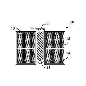
Fig. 1 is cross-sectional view of one type of sensor that can employ the
present
invention's teachings. The sensor 10 is largely cylindrical and includes two
separately
driven coils 12 and 14 displaced axially from each other and isolated by a
housing 16
from the liquid whose viscosity or other property is to be measured. But fluid
is allowed
to flow into a central sample well 18 at whose mouth is located a bob-
retention spider 20,
which confines a ferromagnetic bob 22 to the well 18. Alternately driving the
two coils 12
and 14 causes the bob 22 to reciprocate against the sample liquid's viscous
drag.
Fig. 2 depicts control circuitry for achieving that result. A microprocessor
24 con-
trols an AC-signal generator 26 to cause it to produce an AC signal that an
adder circuit
28 adds to a DC signal from a microprocessor-controlled digital-to-analog
converter 30.
The resultant adder-28 output is a low-level AC voltage superimposed on a DC
voltage
whose level the microprocessor dictates. Filter 28 applies its output to a
high-output-
impedance current driver 32, i.e., a driver whose output current is determined
by the
driver's input largely independently of the load through which that current is
driven. A
switch 34 controlled by the microprocessor determines whether the current from
driver 32
is applied to coil 12 or coil 14.
Microprocessor 24 operates a second switch 36 complementarily to switch 34:
when switch 34 applies the current to coil 12, switch 36 applies to an AC-to-
DC converter
38 a signal that mutual inductance between coils 12 and 14 causes in coil 14
in response
to the drive current's AC component. An analog-to-digital converter 40 applies
to the
microprocessor 24 a digital representation of AC-to-DC converter 38's output,
which is a
DC voltage proportional to the amplitude of the switch-36-forwarded AC signal.
The analog-to-digital converter 40 applies those digital amplitude values to
the
microprocessor 24 periodically, multiple times during a single bob stroke.
When the bob
has reached a predetermined point in that stroke, the microprocessor changes
the states of
the switches 34 and 36 so that coil 14 is the one that is driven and coil 12
is the one
whose voltage is sensed.
One type of measurement that such a circuit can be used to make is a simple
fluid-characterization measurement. This measurement's purpose is to
discriminate
between Newtonian fluids and non-Newtonian fluids as well as between non-
Newtonian
fluids that are pseudoplastic and those that are dilatant.
4
CA 02680520 2009-09-10
WO 2008/118618 PCT/US2008/055794
It will be recalled that absolute (dynamic) viscosity is given by:
= , (1)
where 77 is viscosity, cr is shear stress (shear force per unit area), and rs
is shear rate (veloc-
ity change per unit distance perpendicular to the shear direction).
A fluid is Newtonian if that viscosity is independent of the shear rate, it is
pseudo-
plastic ("shear-thinning") if viscosity decreases with increasing shear rate,
and it is dilatent
("shear-thickening") if its viscosity increases with increasing shear rate.
The illustrated system employs the Fig. 3 routine to discriminate among the
three
fluid types. As that drawing's block 46 indicates, the system is initialized
before the first
stroke by choosing one of the coils as the drive coil, choosing the other as
the detection
coil, and adopting as the initial drive-current level the lower of two levels
that will be used
in characterizing the sample fluid.
As block 48 indicates, the system then begins driving current through the
drive coil
at the selected drive level. As that block also indicates, the system starts
the timer that will
be used in determining relative viscosity, and it starts taking samples of the
detection coil's
signal amplitude.
Bob-position changes that result from the magnetic force that the coil current
causes
tend to change the mutual inductance between the coils, with the result that
the detection-
coil amplitude is a function of bob position. Fig. 4 gives an example of such
a function. As
that drawing shows, the amplitude initially increases as the bob travel
begins. Eventually,
though, it reaches a peak, which the loop represented by Fig. 3's blocks 50
and 52 detects.
As block 54 indicates, the routine then proceeds to identify an end point in
the bob travel by
determining when the detection-signal amplitude has fallen below a
predetermined fraction
of the peak thus detected.
When the system thereby concludes that the bob has reached its end point, the
sys-
tem reads the timer to determine how long the bob took to reach that point,
and it infers the
fluid's viscosity from that timer value. In the illustrated embodiment, it
draws that infer-
ence by using the combination of drive level and travel time to address a look-
up table
(stored, for example, in a data-storage device represented by Fig. 2's block
55) that contains
corresponding viscosity values. These values will typically have been obtained
by calibrat-
5
CA 02680520 2015-05-29
ing the system with various fluids of known viscosities. Some embodiments may
interpolate
between stored values to increase resolution. Other embodiments may dispense
with the
look-up table entirely; the calibration may instead have been used to arrive
the parameters of,
say, best-fit polynomial approximations to the observed calibration data, in
which case the
resultant polynomial determined for the chosen drive level would be used to
calculate the
viscosity from the travel time. (Of course, some embodiments may use formulas
that are not
polynomials and/or that are functions of two or more variables ¨ e.g., drive
level and travel
time ¨ rather than just one.)
Now, the Fig. 3 embodiment's overall purpose is to take viscosity measurements
at
two different levels of drive current and therefore shear rate and to compare
the results to
determine whether the fluid is Newtonian. Instead of simply taking as the low-
shear-rate
viscosity value the result of the block-56 operation's first occurrence, the
illustrated
embodiment takes several such measurements. As block 58 indicates, that is, it
determines
whether it has taken enough low-shear-rate measurements. If it has not, it
takes another
measurement. To that end, it switches coils: as block 60 indicates, it adopts
the erstwhile
detection coil as the new drive coil and the erstwhile drive coil as the new
detection coil. As
that block also indicates, the system would typically turn off the drive
current before making
the switch. The measurement operation is then repeated with the bob traveling
in the other
direction, and such switching continues until enough low-shear-rate viscosity
measurements
have been made.
As blocks 62 and 64 indicate, the system then adopts a high-shear-rate current
as the
level with which to drive the coil, and several measurements are taken at the
high shear rate.
As block 66 indicates, the system then takes respective averages of the high-
and low-
shear-rate measurements, which it compares. As blocks 68, 70, and 72 indicate,
the system
concludes that the fluid is Newtonian ¨ and generates an output indicative of
that conclusion
on, e.g., Fig. 2's display 44 ¨ if the two averages differ by less than a
predetermined
tolerance value. As blocks 74, 76, and 78 indicate, on the other hand, the
output displayed by
the system indicates that the fluid is pseudoplastic if the high-shear-rate
average is less than
the low-shear-rate average by more than the tolerance, and it indicates that
the fluid is
dilatent if the high-shear-rate average exceeds the low-shear-rate average by
more than that
tolerance.
6
CA 02680520 2015-05-29
There are a number of applications in which it is desirable to know not only
whether
the fluid is Newtonian, pseudoplastic, or dilatent but also the degree to
which a pseudoplas-
tic or dilatent fluid exhibits that characteristic. There are a number of
figures of merit
conventionally employed to express the degree to which a fluid exhibits such a
characteristic,
and Fig. 5 is a flow chart of a routine for employing one of them. This
particular routine is
based on the observation that many fluids' behaviors are well approximated by
the following
power-law relationship between viscosity and shear rate in their highest-
viscosity-variation
regimes:
= (2)
where ri is viscosity, K is a constant coefficient, ji is the shear rate, and
n is the so-called
sensitivity factor. If the sensitivity factor n is unity, the fluid is
Newtonian. If 0 <n < 1, the
fluid is shear-thinning, i.e., pseudoplastic. If n> 1, the fluid is shear-
thickening, i.e., dilatent.
The Fig. 5 routine's operations 84-98 will be recognized as essentially the
same as
corresponding operations in the Fig. 3 routine with the exception that,
instead of being
chosen from only two values, the coil-current level adopted in step 84 is
chosen from a larger
number, and an average viscosity value is determined for each of that larger
number of drive
¨ and therefore shear-rate ¨ levels. As blocks 100, 102, 104 and 106 indicate,
the system
steps through measurements at those levels and then turns the coil current
off.
Block 108 represents determining the shear sensitivity from the resultant
observed
relationship between average viscosity and shear rate by finding the value of
n that yields the
best fit of the above-stated power-law relationship to the measured average-
viscosity values.
In doing so, it uses the relationship between shear rate and elapsed time that
the sensor's
geometry dictates. As block 110 indicates, the system generates an appropriate
output to
represent that calculation's result.
As was stated above, the power-law relationship tends to apply to only the
fluid's
highest-viscosity-variation regime, so the operation represented by block 108
may include
identifying that regime by comparing the viscosity values that result from
successive drive
levels. The curve-fitting operation would then be applied to that regime.
Other embodiments
may instead identify that regime by preceding the block-84 operation with
initial viscosity
measurements taken at widely spaced drive levels, in which case the drive
levels chosen in the
block-104 operation can be restricted to those in the power-law regime.
7
CA 02680520 2015-05-29
In any event, the output generated in the block-110 operation can take any of
a wide
variety of forms. For example, it may simply be the numerical value of the
shear sensitivity n
itself. It could be that value together with an indication, in terms of, say,
the shear-rate range, of
the regime in which the determined power-law relationship prevails. Yet
another type of output
may be a plot of viscosity as a function of shear rate, possibly in addition
to one or both of the
numerical values mentioned above.
Particularly in the latter connection it is sometimes instructive to take into
account the
fact that some fluids exhibit a shear-rate "memory": the viscosities that they
exhibit can depend
on the shear rates that they have recently experienced. One way to take this
into account is to
perform the Fig. 5 operation twice, once in increasing-drive-level order and
once in decreasing-
drive-level order, and to produce an output plot that shows the resultant
"hysteresis," which Fig. 6
illustrates.
By a slight change, the approach described by reference to Fig. 5 for
determining shear
sensitivity can also be used to provide an output indicative of shear stress
as a function of shear
rate to produce, say, a graphical output such as that which Fig. 7 depicts.
Specifically, the
operation of Fig. 5B's block 108 can be replaced with one in which shear
stresses are computed
for respective rates from that routine's previous measurements.
Since known-viscosity fluids were used to arrive at the illustrated
embodiment's look-up-
table or algorithmic relationship between viscosity and the combination of
drive level and travel
time, those known relationships can be used to obtain viscosity in Fig. 5A's
block-94 operation as
an intermediate value, and the shear stress can be calculated as the product
of shear rate and the
thus-determined viscosity. Of course, some embodiments may instead obtain
shear stress more
directly, without the intermediate viscosity computation; the relationship
between shear stress and
coil current can be obtained from the sensor geometry and relationships
(typically determined
during a calibration operation) between coil current and resultant magnetic
force on the bob.
Another type of measurement that reciprocating-bob sensors can be used for is
the
detection of fluid complexity, i.e., of the tendency of a fluid's viscosity to
change with time when
it is being sheared. Fig. 8 depicts an approach that can be used for that
purpose. This
measurement would likely be made over a relatively extended time period; a
duration of half an
hour may be used, for instance. As block 112, indicates, therefore, the
operation's initialization
includes setting a "long timer" intended for such durations. The operations
8
CA 02680520 2009-09-10
WO 2008/118618 PCT/US2008/055794
that blocks 114, 116, 118, 120, 122, and 124 represent will be familiar from
previous rou-
tines as the operations by which the system causes the bob to reciprocate and
make viscos-
ity determinations based on its motion. Block 126 indicates that this
reciprocation and vis-
cosity measurement continue until the long timer has timed out. Typically,
this measure-
s ment is made with the same drive-current level on each stroke.
As block 128 indicates, the system then generates an output that tells whether
shear-
ing has caused drift in the fluid's viscosity. In the illustrated embodiment,
that is done by
presenting as a graphical output a plot of filtered viscosity values as a
function of time. The
filter is used for noise suppression and may, for instance, produce the
viscosity's exponen-
tial average. Other embodiments may instead or additionally state whether the
fluid is
complex or not, basing that determination on whether a detected change exceeds
some
threshold, and, if it is complex, whether it is rheopectic (thickening over
time) or
thixotropic (thinning over time).
The reciprocating-bob sensor can also be used to determine yield stress. Some
flu-
ids do not flow until they are subjected to a threshold stress, and Fig. 9
depicts one routine
for determining that threshold. Block 130 represents initialization for the
routine as a
whole, while block 132 represents initialization for a single stroke. As block
132 indicates,
the drive current is initially zero, and, as blocks 134, 136, 138, and 140
indicate, it increases
incrementally with a rest interval between increases until the detection
coil's signal indi-
cates that the bob has moved from the initial position. Once that motion has
been detected,
the system keeps driving the bob in the same direction (with, in the
illustrated embodiment,
the same drive current) until it reaches the end-of-stroke position as
determined in an opera-
tion that block 142 represents. As blocks 144, 146, and 148 indicate, the
system repeats
this operation, inferring yield stress from the current that was applied when
initial move-
ment was detected and averaging the result with previous measurements, until
some prede-
termined number of such measurements have been made. As block 150 indicates,
the rou-
tine then generates an output indicating the average yield-stress value,
although, as
block 146 indicates, it may also output intermediate values, too.
The above-described routines that determine viscosity do so by timing the
bob's
travel through a predetermined distance. In this respect, their uses of the
sensor are similar
to those that conventional approaches employ. In contrast, the routine of Fig.
10 deter-
mines viscosity by measuring the distances traveled by the bob in
predetermined time in-
crements: the measured quantity is distance rather than time. The particular
approach that
9
CA 02680520 2009-09-10
WO 2008/118618 PCT/US2008/055794
Fig. 10 employs tends extend the range of viscosities that a given sensor can
be employed
to measure. It does this by making incremental velocity measurements: it makes
multiple
measurements in the span of the single bob stroke or less. That routine can be
used simply
to make a viscosity measurement or it can be employed as a constituent of a
more-elaborate
rheological measurement. It can, for example, be substituted for the
operations of Fig. 3's
blocks 50, 52, 54, and 56, Fig. 5's blocks 88, 90, 92, and 94, and Fig. 8's
blocks 116, 118,
120, and 122.
For purposes that will become apparent, the Fig. 10 routine begins in an
initializa-
tion operation that block 152 represents. That initialization operation
includes setting a flag
io to a state that indicates that the bob motion is currently in an
acceleration regime rather than
a terminal-velocity regime. Additionally, the system resets a terminal-
velocity-
measurement counter to zero, as block 152 indicates. As will be described in
more detail
below, that counter indicates how many individual velocity measurements have
been made
in the terminal-velocity regime.
With that flag and counter set, the system begins driving the bob
electromagneti-
cally in the manner explained above. Periodically during the resultant bob
stroke it meas-
ures the amplitude of the detection coil's output signal, as block 154
indicates. By employ-
ing one of the approaches mentioned above the system then converts the
amplitude meas-
urement to a position value, as block 156 indicates.
These position measurements will be used to compute velocity at various points
along the stroke. Of course, a velocity determination can be made from only
two position
measurements, and some embodiments may employ only two position measurements
for
each velocity calculation. For noise-suppression purposes, though, other
embodiments may
employ three or more position measurements and use some type of filtering
approach to
arrive at a velocity value.
Since a velocity calculation requires multiple position measurements, not
enough
position values will be available initially. As block 158 indicates,
therefore, the system
computes no velocity values until enough position values have been taken.
After they have,
the system computes a velocity for each subsequent position value, as block
160 indicates,
by using as position-measurement window that overlaps the window used for the
previous
velocity computation. If the fluid is relatively inviscid, the bob may travel
through a sig-
nificant portion of its stroke before it reaches its terminal velocity. The
velocities observed
CA 02680520 2009-09-10
WO 2008/118618 PCT/US2008/055794
in this initial, pre-terminal-velocity portion of its stroke result partially
from inertial effects,
so the accuracy of viscosity determinations made in that regime can suffer if
appropriate
provisions are not made to take those inertial effects into account.
The routine that Fig. 10 depicts employs two alternative approaches to making
such
provisions. The first is simply to avoid velocity measurements in that initial
portion of the
stroke. As was mentioned above, the system assumes at the beginning of the
stroke that the
bob is in an acceleration phase, where inertia significantly affects bob
velocity. In a man-
ner that will described below, the system therefore tests the position
measurements to de-
termine whether it should assume that the bob has reached the terminal-
velocity portion of
its travel. Block 162 represents checking the flag that indicates whether the
system has al-
ready concluded that this regime has been reached. If the terminal-velocity
regime has not
yet been assumed, i.e., if the flag indicates that the system has not yet
concluded that the
bob has reached its terminal velocity, the sensor determines whether such a
conclusion
would now be justified. As block 164 indicates, it does this by determining
whether the
just-computed velocity exceeds the previously determined velocity by more than
some pre-
determined increment. If not, the system switches the flag, as block 166
indicates, to the
terminal-velocity-regime-indicating value
Once the bob has entered the terminal-velocity regime, some number of velocity
de-
terminations thereafter made will be the basis for a viscosity computation. To
keep track of
whether the requisite number of terminal-velocity measurements have been made,
the sys-
tem uses a counter, which block 168 represents incrementing. As block 170
indicates, the
system then returns to make another of the terminal-velocity-regime
measurements if the
bob has not reached the end of its travel.
The end-of-travel determination can be made in the above-mentioned manner, in
which it is based on whether the detection-coil output has fallen to a
predetermined fraction
of its peak value. But another approach, which for some sensor arrangements is
more accu-
rate, is to observe whether the bob has reached a hard stop, i.e., to
determine whether two
successive position measurements are equal or nearly so.
In any event, the block-170 operation's conclusion will ordinarily be that the
bob
has not reached the end of its travel, so the system returns to make a further
terminal-
velocity-regime measurement. This time, the determination represented by Fig.
5's
block 162 is affirmative, representing the system's conclusion that the
terminal-velocity
11
CA 02680520 2009-09-10
WO 2008/118618 PCT/US2008/055794
regime has been reached, so the system does not return to the block-164
determination. In-
stead, it performs the operation represented block 172, in which it reads the
terminal-
velocity counter to determine whether enough terminal-velocity measurements
have been
made to provide a good basis for a viscosity computation. If not enough have,
that velocity
measurement is simply stored, and the system repeats the block-168 and -170
operations of
incrementing the terminal-velocity counter and making the end-of-travel
determination.
This loop continues in most cases until the block-172 determination is
affirmative, i.e., until
enough terminal-velocity-regime measurements have been made. When enough have,
the
routine performs the block-174 operation of averaging the velocity
measurements that were
io made in the terminal-velocity regime; the average is based only on those
measurements and
not on any of the velocities that were observed during the initial,
acceleration regime.
In some embodiments, the criterion applied by the block-172 determination may
not
be a fixed number of terminal-velocity-regime velocity measurements; the
system may, for
example, merely continue to take terminal-velocity-regime velocity
measurements until the
bob reaches the end of its stroke, and all of the measurements thus taken
contribute to the
average. In other embodiments, though, the criterion may be a predetermined
number so
that a first viscosity (or other velocity-related-quantity) computation can be
completed be-
fore a full stroke ends. The rest of the stroke can then be used for another
computation of
viscosity (or, e.g., shear rate), possibly based on a different drive current.
As block 176 indicates, the system infers viscosity (or some other velocity-
related
quantity) from the average velocity value in one of the ways mentioned above.
The routine
ends after the block-178 operation of generating an appropriate output
indicative of that
value. In some cases that output will simply be a presentation on a human-
readable display.
In other cases it may, for instance, be provided as one constituent input to
some fluid-
characteristic determination based on some number of such values or on one or
more such
values together with values of one or more other physical quantities.
As was mentioned above, the routine actually provides for two alternative ap-
proaches to determining viscosity. The first one, just described, is the one
that is employed
in situations in which the terminal-velocity regime's duration is long enough
to provide
enough terminal-velocity-regime measurements for a determination of viscosity
or other
desired quantity. In some cases, though, the viscosity is so low that too few
velocity meas-
urements have been taken in the terminal-velocity regime. In such cases, there
will eventu-
12
CA 02680520 2009-09-10
WO 2008/118618 PCT/US2008/055794
ally be an affirmative outcome of the block-170 determination: the bob will
reach the end
of its travel before enough terminal-velocity-regime measurements been made.
In that situation, the system employs an alternative approach, in which it
infers ve-
locity by mathematically matching dynamic motion curves to the position
measurements
that were taken during the stroke. For example, the system may have previously
deter-
mined that the sample fluid is Newtonian. In that case, it may be assumed that
the equation
of motion will be of the form:
(3)
dt2 g dt
where m is the bob's mass, y is its position, kg is a geometry-determined
coefficient that re-
lates the viscous drag on the bob to the fluid's viscosity ri and the bob's
speed, and F is the
(in the illustrated embodiment, substantially constant) magnetic force on the
bob. That dif-
ferential equation's solution for boundary value y = dy/dt = 0 at t = 0 is
y(t) = [t ¨(1¨ e-t I r)1]-vT , (4)
where VT= Flke is the bob's terminal velocity and r = m/kgri is the time
constant with
which the bob's velocity approaches VT.
Since the force F and coefficient kg will be known, the fluid's viscosity can
be com-
puted from the bob motion's time constant T or terminal velocity VT. So all
that is necessary
is to use some curve-fitting routine to find the time constant that results in
the best match of
the observed position values to the above differential-equation solution. One
approach, for
example, is to begin by assuming a trial time constant equal to, say, the just-
observed stroke
time and to use this assumed time-constant value to compute a respective
terminal-velocity
value from each of a plurality of the observed (time, position) pairs in
accordance with the
following equation:
= y(t)
(5)
If the assumed time constant is correct, each of the terminal-velocity values
thus de-
termined will be approximately the same. If the assumed time constant is too
low, though,
they will increase with time, and they will decrease with time if it is too
high. By employ-
ing those facts, the system can arrive at the correct time constant, and
therefore the correct
viscosity value, by successive approximation.
13
CA 02680520 2009-09-10
WO 2008/118618 PCT/US2008/055794
By employing the present invention's teachings, a wide range of rheological
meas-
urements can be made inexpensively. The invention therefore constitutes a
significant ad-
vance in the art.
14