Note: Descriptions are shown in the official language in which they were submitted.
CA 02680706 2015-04-02
USE OF STATISTICAL ANALYSIS IN POWER PLANT
PERFORMANCE MONITORING
Technical Field
[0002] This patent relates generally to the control and implementation of
power generating
equipment in power plants, including for example turbine based power plant
systems or other
steam generating power plant systems.
Background
[00031 A variety of industrial as well as non-industrial applications use fuel
burning boilers
which typically operate to convert chemical energy into thermal energy by
burning one of
various types of fuels, such as coal, gas, oil, waste material, etc. An
exemplary use of fuel
burning boilers is in thermal power generators, wherein fuel burning boilers
generate steam from
water traveling through a number of pipes and tubes within the boiler, and the
generated steam is
then used to operate one or more steam turbines to generate electricity. The
output of a thermal
power generator is a function of the amount of heat generated in a boiler,
wherein the amount of
heat is directly determined by the amount of fuel consumed (e.g., burned) per
hour, for example.
[0004] In many cases, power generating systems include a boiler which has a
furnace that burns
or otherwise uses fuel to generate heat which, in turn, is transferred to
water flowing
CA 02680706 2009-09-11
WO 2008/112823 PCT/US2008/056741
through pipes or tubes within various sections of the boiler. A typical steam
generating
system includes a boiler having a superheater section (having one or more sub-
sections) in
which steam is produced and is then provided to and used within a first,
typically high
pressure, steam turbine. To increase the efficiency of the system, the steam
exiting this first
steam turbine may then be reheated in a reheater section of the boiler, which
may include one
or more subsections, and the reheated steam is then provided to a second,
typically lower
pressure steam turbine. While the efficiency of a thermal-based power
generator is heavily
dependent upon the heat transfer efficiency of the particular furnace/boiler
combination used
to burn the fuel and transfer the heat to the water flowing within the various
sections of the
boiler, this efficiency is also dependent on the control technique used to
control the
temperature of the steam in the various sections of the boiler, such as in the
superheater
section of the boiler and in the reheater section of the boiler.
100051 The steam turbines of a power plant are typically run at different
operating levels at
different times to produce different amounts of electricity based on energy or
load demands.
For most power plants using steam boilers, the desired steam temperature
setpoints at final
superheater and reheater outlets of the boilers, as well as other settings
within the system, are
kept constant, and it is necessary to maintain steam temperature setpoints as
well as other
operating parameter setpoints close to a set of preestablished setpoints
(e.g., within a narrow
range) at all load levels. These setpoints may, in many cases, be set
according to the use of
manufacturer reference values and correction curves.
[0006] As is known, the efficiency of the operation of power plants, including
steam
generating or turbine power plants, is based on a number of factors within the
plant,
including not only the operating state of the equipment, but the type of
control being applied
at any particular time. In past decades, power plants, and especially power
plants coupled to
2
CA 02680706 2009-09-11
WO 2008/112823 PCT/US2008/056741
and providing power on the public power grid, were generally run at fairly
constant outputs,
and thus could be optimized over time using various techniques developed by
the ASME. At
the present time, however, the power (electricity) market is moving to a
deregulated market,
which allows for, and in fact encourages, constantly changing the amount of
power being
placed on the power grid by any particular utility or power plant based on
market factors.
This change in the marketplace leads to a situation in which the power being
generated by a
particular plant may be typically in flux or changing. This factor, in
conjunction with the fact
that the market is moving to ISO types of structures, has led to the increased
role of computer
control and diagnostic systems, which is rendering previous performance
methodologies
obsolete. In particular, several key aspects within these previous performance
methodologies, including the use of manufacturer based reference values and
correction
curves, may lead to highly imprecise and inadequate evaluation of plant
performance,
especially considering operational behavior in a dynamic electricity market in
which it is
very important to be able to quantify plant performance quickly and
accurately, to be able to
profitably supply power in changing market conditions.
100071 The plant performance methodology that is currently being used to
implement
performance monitoring in power plants was developed more than 20 or 30 years
ago for
power units operating with the expected conditions in the power industry. That
methodology
was developed based on, and corresponded to, the American and Western Europe
standards
of the 1960s and 70s, which put a premium on reliability (and not necessarily
on efficiency).
While this methodology, at the time, brought many significant advantages in
the form of an
improved quality of performance monitoring, it is outdated by the current
dynamic
deregulation aspects of the power generation industry. This obsolescence is
due to a couple
of factors, including (1) the advancement of computer technology that allows
for common
3
CA 02680706 2009-09-11
WO 2008/112823 PCT/US2008/056741
use of digital automatic control systems and (2) system changes in the power
energy market.
As a result, using this older performance analysis approach becomes less
viable as a true
performance index of a plant capability.
100081 Generally speaking, the plant performance monitoring methodology that
is
currently being implemented to measure plant performance is based on
calculating the unit
chemical energy usage rate (using ASME power test codes) and then assigning
measured loss
deviations of the unit chemical energy usage rate from the expected value
(i.e., a nominal
value resulting from the last design or warranty measurements) as a result of
operating the
unit at parameters other than at the nominal parameters. The basic parameters
whose
influence over the unit heat rate is usually taken into consideration include
main steam
pressure, main steam temperatures, pressure decrease in the superheater (SH),
reheat steam
temperature (RH), pressure in the condenser, temperature of feedwater, and
oxygen content
in flue gas and flue gas temperature. While the number of these parameters has
been
extended many times, the theoretical basis of this method has stayed the same,
in which the
deviation in unit heat rate [kJ/kWh](BTU/ kW) is usually calculated to a value
of dollars per
hour ($/h) for a more visual presentation of data. Systems such as this, which
are based on
ASME, TICE or similar methodologies, have been introduced in practically all
power plants.
With the modernization of automatic control systems, these methods have
developed into an
on-line system which performs all of the performance monitoring calculations,
e.g., every
several minutes, and presents the results on an operators' display screens at
the distributed
control system or at auxiliary computer displays to enable the operators to
see the loss in
efficiency of the plant and cost due to current operating conditions.
100091 While the ASME performance monitoring methodology is effective when
properly
implemented, it has drawbacks. In particular, it is apparent, after so many
years (and after
4
CA 02680706 2009-09-11
WO 2008/112823 PCT/US2008/056741
many platform revisions), that there are basic problems with applying the
current
performance monitoring applications, due in large part to the use of original
equipment
manufacturer (OEM) provided "reference values" and "correction curves" that
define the
controlled (i.e., measured) losses from a particular operating point within
the power plant.
More particularly, in the current performance measuring system, most
performance
deviations (losses) are calculated (or are monitored) based on deviations from
a set of so-
called "reference values" which are usually the nominal values given by the
OEM
manufacturer. However, for devices that often have a 10-20 year life cycle,
and that may
have been modernized numerous times during their life, the OEM supplied
reference values
do not constitute a real reflection of the actual, as found parameters, within
a particular
power plant. Additionally, the present ASME methodology assigns the influence
of
operational parameter deviation (deviations in temperature, pressure, etc.
during plant
operation) from the assumed nominal values (i.e., the assumed achievable,
design, or
theoretical values) using the manufacturer's so-called "correction curves."
Leaving aside the
accuracy of these correction curves in the first place (as there are common
problems with
obtaining these correction curves), the basis of this theory relies on
defining the influence of
deviations in the current operating parameters from the nominal or reference
value on the
unit heat rate (efficiency).
100101 Unfortunately, the manufacturer's data, in the form of both the
reference values and
the correction curves, does not necessarily correspond to the real, dynamic
operation of a
particular maintained unit. Instead, this data is, at best, indicative of the
average or assumed
steady-state performance of a new unit. There is thus a serious theoretical
problem with
assigning a deviation for a given control value in a particular plant, which
may not operate
the same as the new unit for numerous reasons, based on these reference values
and curves in
CA 02680706 2009-09-11
WO 2008/112823 PCT/US2008/056741
the first place. Moreover, when building a correction curve, the manufacturer
assumes that it
is possible to make a clear assignment of the influence of a given operating
parameter value
on the unit heat rate without considering any other operating parameter. In
other words, it is
assumed that operating variables such as pressure, temperature, etc., can be
treated as
independent variables, which allows the method to apply balance calculations
using the
correction curves to calculate the effect of a change in an individual
parameter on the plant
efficiency (unit heat rate). In actual practice, however, a strong inter-
relationship or
interdependence exists between the various plant operating parameters. For
example, various
operating parameters are known to be highly interrelated in the form of the
turbine equation.
As a result, while the current performance methodology assumes that it is
possible to modify
one parameter without changing other parameters, during normal operation of
the plant it is
not possible to change one parameter without changing a few others.
Additionally, the
relationships between these parameters is not only dependent on the
thermodynamic
dependencies (balance), but are also influenced by the operation of the
automatic control
system that is actually controlling the unit. These relationships are simply
ignored in the
current methodology. In practice, therefore, when changing one of the main
unit operational
parameters, the automatic control systems shifts the unit status into a
different operating
point by also modifying the other parameters.
100111 Because of these factors, deviations assigned using OEM correction
curves cease to
have any practical significance. For example, if, at a given moment,
deviations of a unit heat
rate are assigned for a series of main parameters, and a negative deviation
for one of the
parameters is obtained (resulting from the difference between the current
value and the
nominal or reference value), and if this difference is cancelled (i.e., the
parameter is brought
to the nominal or reference value to reduce the deviation), the other
parameters will not
6
CA 02680706 2009-09-11
WO 2008/112823
PCT/US2008/056741
remain unchanged, even though the performance methodology assumes that the
other
parameters will remain unchanged. This real life operation results in an
entirely different set
of parameter values, which will have other differences from the corresponding
reference
values, resulting in a completely different set of deviations to be corrected.
[0012] Still
further, there is a problem with applying statistical balance models to assign
losses during load following (i.e., dynamic) unit operation using the current
ASME
performance measurement methodology. In particular, the models used in current
performance monitoring methodologies are based on a strictly static approach,
i.e., based on
the static operation of the plant. As a result, a good thermal status (or
quasi-static) isolation
of the unit operation is needed to obtain relevant performance monitoring
results using these
models. In the simplest approach, this static isolation requires a momentary
stabilization of
unit power and its principal parameters. However, in the power generation
conditions
associated with the present (ISO or deregulated) market, using a strictly
static approach is
simply impossible. In fact, the entire theory behind unit operation that
actively participates
in the power market assumes operation during dynamic (ramping or transitional)
states.
[0013] Still further, the approach for obtaining good global performance
results is to
perform diverse processing of static performance data, which averages the
results from
various sites (considering the normal distribution of calculation errors and
influence of
dynamic states) thereby canceling momentary error. However, using this
methodology for
temporary (dynamic) performance monitoring is questionable at best.
Summary
[0014] A method of implementing performance monitoring in a power plant
described
herein is appropriate to control operating parameters and factors connected
with the
7
CA 02680706 2009-09-11
WO 2008/112823 PCT/US2008/056741
efficiency of the energy production process in an energy marketplace that is
more complex
than in the past, and that takes into account more than just the cost of fuel.
In particular, this
method works well when the real costs of production are largely dependent on
other variable
costs besides the cost of fuel, such as environmental credits (e.g., the cost
of NOx, SOx
emissions and the future influence of emission trade), equipment degradation
and repair
costs, as well as electrical energy trade market factors like ramp rate, LMP
factors, and the
ability to deliver contracted power levels and spot transactions.
[0015] In particular, a power plant performance monitoring technique applies a
unique
statistical analysis to collected power plant data to determine the factors
that are best
controlled or changed to affect (increase) the efficiency or other primary
performance
indication of the plant, in whatever state or operating level the plant is
run. Because heat rate
calculation applications are typically performed on-line, it is possible to
analyze collected
plant data in detail and to apply for example, principal component analysis
(PCA) and linear
and nonlinear regression analysis to the data, which enables the performance
method to
obtain a more accurate determination of the influence of the principal process
parameters that
affect heat rate deviation (efficiency), as well as to establish baseline or
best-possible
operational constraints to be used to control the plant in the future. This
performance based
control methodology will allow for near optimum performance of power plants by
constantly
allowing for refinement and best practices and control to be realized.
Brief Description of the Drawings
[0016] Fig. 1 illustrates a block diagram of a power plant having a typical
boiler steam
cycle for a set of steam powered turbines.
8
CA 02680706 2009-09-11
WO 2008/112823
PCT/US2008/056741
100171 Fig. 2 illustrates a flowchart of a method for performing plant
performance
monitoring and adjustment using statistical analysis.
100181 Figs. 3A-3E illustrate a set of histograms developed from collected
plant
operational data for a primary performance indication and for a number of
plant parameters
that are related to the primary performance indication during various
different operational
states of two different power plants.
100191 Fig.
4 illustrates a plot of a resulting principal component analysis illustrating
the
manner in which the plant parameters of Figs. 3A ¨ 3E correlate to the primary
performance
indication during the different operational states of the different plants.
[00201 Fig. 5 illustrates a correction curve generated for a particular
operating parameter
as related to a primary performance indication using collected data from a
power plant.
Detailed Description
[0021] Digital, computer based, automatic control systems now present in many
power
plants allow for almost constant monitoring and control of plant performance
by monitoring
all performance parameters (and losses) on-line and by permitting direct
operator supervision
and oversight. The increase in the quality of measurement devices and tools
has also
dramatically reduced the role of periodic heat rate testing and warranty
measurements.
However, the high quality nature of automatic distributed control systems
(DCS) connected
with common optimization systems (which substitute for operator actions during
normal unit
operation) has reduced the possibility of obtaining simple improvements in
efficiency
indexes. For this reason, the principal role of performance supervision can
now be modified
to that of performing real detection of possible losses associated with
running a particular
power unit in a market based generation dispatch manner.
9
CA 02680706 2009-09-11
WO 2008/112823 PCT/US2008/056741
100221 To implement this goal, a new method of implementing power plant
performance
monitoring and control includes collecting and storing statistical data
pertaining to the
operation of the various units or sub-sections of a power plant, and then
performing a
statistical analysis on the data to determine which parameters are most highly
correlated with
one or more performance indications of the plant, such as plant efficiency,
unit heat rate, etc.
Subsequent control activities may then be implemented within the power plant
to control the
identified parameters in a manner that provides a high degree of control on
the parameters
most correlated or responsible for changes in the performance indication,
while, if necessary,
allowing other parameters to range outside of nominal, suggested or
predetermined limits or
ranges, so as to provide better (more optimal) plant operation. In this
manner, performance
monitoring and control is based on the actual operational conditions of a
particular power
plant for which data is collected, instead of being based on a theoretical or
test power plant.
Moreover, instead of being limited to using the cost of fuel as the only cost
variable in
determining the unit heat rate or other efficiency measure, other cost or
income variables
(factors) can be taken into account in the performance calculations, such as
the cost of
emissions, equipment repair costs, carbon credits, etc.
[0023] Before discussing the new performance monitoring methodology, a typical
power
plant in which this methodology can be implemented will be described in a
general manner.
Fig. 1 illustrates a block diagram of a once-through boiler steam cycle for a
typical boiler 100
that may be used in, for example, a thermal power plant. The boiler 100 may
include various
sections through which steam or water flows in various forms such as
superheated steam,
reheated steam, etc. While the boiler 100 illustrated in Fig. 1 has various
boiler sections
situated horizontally, in an actual implementation, one or more of these
sections may be
positioned vertically with respect to one another, especially because flue
gases heating the
CA 02680706 2009-09-11
WO 2008/112823 PCT/US2008/056741
steam in various different boiler sections, such as a water wall absorption
section, rise
vertically (or, spirally vertical).
100241 In any event, as illustrated in Fig. 1, the boiler 100 includes a
furnace and a primary
water wall absorption section 102, a primary superheater absorption section
104, a
superheater absorption section 106 and a reheater section 108. Additionally,
the boiler 100
may include one or more desuperheaters or sprayer sections 110 and 112 and an
economizer
section 114. During operation, the main steam generated by the boiler 100 and
output by the
superheater section 106 is used to drive a high pressure (HP) turbine 116 and
the hot reheated
steam coming from the reheater section 108 is used to drive an intermediate
pressure (IP)
turbine 118. Typically, the boiler 100 may also be used to drive a low
pressure (LP) turbine,
which is not shown in Fig. 1.
[0025] The water wall absorption section 102, which is primarily responsible
for
generating steam, includes a number of pipes through which water or steam from
the
economizer section 114 is heated in a furnace. Of course, feedwater coming
into the water
wall absorption section 102 may be pumped through the economizer section 114
and this
water absorbs a large amount of heat when in the water wall absorption section
102. The
steam or water provided at output of the water wall absorption section 102 is
fed to the
primary superheater absorption section 104, and then to the superheater
absorption section
106, which together raise the steam temperature to very high levels. The main
steam output
from the superheater absorption section 106 drives the high pressure turbine
116 to generate
electricity.
[0026] Once the main steam drives the high pressure turbine 116, the steam is
routed to the
reheater absorption section 108, and the hot reheated steam output from the
reheater
11
CA 02680706 2009-09-11
WO 2008/112823 PCT/US2008/056741
absorption section 108 is used to drive the intermediate pressure turbine 118.
The spray
sections 110 and 112 may be used to control the final steam temperature at the
inputs of the
turbines 116 and 118 to be at desired setpoints. Finally, the steam from the
intermediate
pressure turbine 118 may be fed through a low pressure turbine system (not
shown here), to a
steam condenser (not shown here), where the steam is condensed to a liquid
form, and the
cycle begins again with various boiler feed pumps pumping the feedwater
through a cascade
of feedwater heater trains and then an economizer for the next cycle. The
economizer section
114 is located in the flow of hot exhaust gases exiting from the boiler and
uses the hot gases
to transfer additional heat to the feedwater before the feedwater enters the
water wall
absorption section 102.
100271 As illustrated in Fig. 1, a controller or control system 120 is
communicatively
coupled to the furnace within the water wall section 102 and to valves 122 and
124 which
control the amount of water provided to sprayers in the spray sections 110 and
112. The
controller 120 is also coupled to various sensors, including temperature
sensors 126 located
at the outputs of the water wall section 102, the desuperheater section 110,
the second
superheater section 106, the desuperheater section 112 and the reheater
section 108 as well as
flow sensors 127 at the outputs of the valves 122 and 124. The controller 120
also receives
other inputs including the firing rate, a signal (typically referred to as a
feedforward signal)
which is indicative of and a derivative of the load, as well as signals
indicative of settings or
features of the boiler including, for example, damper settings, burner tilt
positions, etc. The
controller 120 may generate and send other control signals to the various
boiler and furnace
sections of the system 100 and may receive other measurements, such as valve
positions,
measured spray flows, other temperature measurements, etc. While not
specifically
illustrated as such in Fig. 1, the controller 120 could include separate
sections, routines
12
CA 02680706 2015-04-02
and/or control devices for controlling the superheater and the reheater
sections of the boiler
system 100.
[0028] As illustrated in Fig. 1, a performance monitoring system 140 includes
a data collection
system 142 that collects data from each of the various devices within the
boiler 100 or the power
plant pertaining to the values of various parameters within the power plant at
any particular time
(e.g., the steam and water temperatures, pressures, control signals, etc.). In
particular, the data
collection system 142, which may include a database and an appropriate
interface, is illustrated
in Fig. 1 as being connected directly to the controller 120 to receive data
from the controller 120
related to the ongoing operation of each of numerous devices within the system
100, such as the
devices 102, 104, 124, 126, 127, etc. However, the data collection system 142
could instead or
additionally be communicatively connected to any or all of the devices 102,
104, 124, 126, 127,
etc. within the plant 100 to receive data about the operating states or
conditions of those devices
at numerous times during operation of the plant 100. Generally speaking, the
data collection
system 142 will periodically receive and store data pertaining to the
operational conditions or
states of the various devices or operating parameters within the plant 100
(such as temperatures,
pressures, etc.) and will store this data for future analysis.
[0029] While not specifically illustrated in Fig. 1, the data collection
system 142 may
collect data pertaining to the operating output or load of the plant based on
fuel input, load
output measurements, etc. and may correlate this data with the operating data
collected from the
system 100. Moreover, the data collection system 142 may obtain and store data
about other
variables that affect or form a part of performance or efficiency calculations
(e.g. unit heat rate,
Q, etc.). The data collection system 142 may also collect data regarding other
factors going into
or making up a plant performance measure, which factors may include, for
13
CA 02680706 2009-09-11
WO 2008/112823 PCT/US2008/056741
example, the amount of particular emissions emanating from the plant as a
result of
operations at any particular time, the regulatory cost of those emissions at
any particular
time, the cost of carbon credits needed by the plant based on operation of the
plant,
equipment degradation and repair costs, the income generated by the production
of carbon
credits produced in the plant, the price being provided for particular power
at particular
times, as well as other electrical energy trade market factors like ramp rate,
LMP factors, and
the costs or income associated with delivering power at contracted power
levels and as a
result of spot transactions.
100301 The performance monitoring system 140 also includes a performance
monitoring
engine 144 connected to a user interface 146 which may be located at or as
part of, for
example, a user workstation associated with the plant. The engine 144, which
may be
implemented for example in programming executed on a general purpose or a
specially
designed processor, periodically or at user specified times, obtains the data
stored in the
database 142 and analyses that data to implement performance monitoring, the
results of
which may be illustrated to a user via the user interface 146. In particular,
the engine 144
performs statistical analysis on the stored data to produce certain types of
information for the
user to assist the user in viewing and understanding the manner in which the
plant is able to
operate, for example, from an efficiency standpoint. The statistical
information generated by
the engine 144 may also enable the user to more effectively modify the
operation of the plant
to increase the efficiency of the plant, or to at least understand the
expected or achievable
efficiency of the plant based on actual past performance of the plant.
100311 More particularly, the operation of the performance monitoring engine
144 extends
the possibility of performance monitoring in a power plant using a deep
statistical analysis of
collected process data as well as other efficiency data. Generally speaking,
in power
14
CA 02680706 2009-09-11
WO 2008/112823 PCT/US2008/056741
generation units equipped with a digital automatic control system, the heat
rate calculations
are, in practice, engineered to run on-line and can be collected or determined
by the engine
144 on a periodic basis. In other words, as a result of the operation of the
data collection
system 142 in conjunction with the infrastructure already provided by a
typical digital control
system, a large number of calculation data is available, and this data can be
used in a
statistical analysis as a valuable tool to determine useful performance
monitoring
information. In the discussion below, it is assumed that traditional
measurement and
calculation techniques are implemented to increase the reliability of the
collected data,
including, for example, assuring the credibility of measurement devices,
insuring that the
basic measurements (especially flow measurements) operate correctly and are of
an
appropriate measurement class, insuring that the influence of delayed chemical
analysis of
fuel (when there are no on-line analyzers) is taken into account, insuring
that process data
and results are appropriately processed to eliminate measurement errors, etc.
This last point
may be accomplished, in one example, by filtering out data collected during
non-stationary
states of the units, etc. However, upon solving these data collection
problems, a large,
credible base of calculation data and unit heat rate data (or other
performance indication data)
for different unit operating states of the power plant is obtainable.
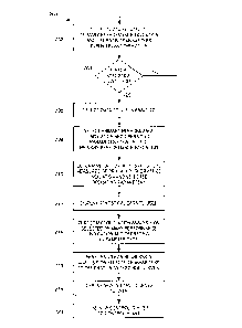
10032i Fig. 2 illustrates a flow diagram 200 of a method or a procedure that
may be
implemented by the performance monitoring system 140 of Fig. 1. At a block
202, the data
collection system 142 collects data related to a primary performance
indication as well as
data related to a number of operating parameters within the power plant that
may have an
affect on the primary performance indication. The primary performance
indication may be,
for example, plant efficiency, unit heat rate, etc. and various types of data
may be collected to
determine this indication including, for example, the costs, amounts and types
of fuels being
CA 02680706 2009-09-11
WO 2008/112823 PCT/US2008/056741
used, the amounts of and the costs associated with release of regulated
emissions, carbon
credits, costs associated with plant equipment repair and replacement, etc.
Additionally, the
operating parameters of the power plant may include any measured parameter
within the
power plant (either Combined Cycle or Conventional Boiler/turbine), including
those
otherwise listed herein as well as, for example, air heater gas inlet and
outlet temperatures,
flue gas CO content, flue gas CO2 content, fuel(s) analysis, heating value of
fuel(s), fuel
cost(s), air heater air inlet/outlet temps, air heater gas inlet/outlet temps,
02 at economizer, 02
after air heaters, primary and/or secondary air flows, cooling water inlet
temperature, cooling
water outlet temperature, condenser back pressure, makeup water flow, makeup
water
temperature, condenser hotwell temperature, generator gross power output,
generator
megavars, hydrogen pressure (if generator is hydrogen cooled), auxiliary
power, steam
turbine throttle steam temperature/pressure, turbine exhaust
pressure/temperature, hot reheat
temperature and pressure, 1P/LP crossover steam temperature and pressure, for
each BFP
pump suction and discharge temperature and pressure, water flow through pumps,
pump
speed, pump motor current, ambient air temperature, ambient relative humidity,
ambient
barometric pressure, Combustion Turbine Generator (CTG) fuel flow, CTG power,
compressor inlet temperature, compressor outlet pressure (CPD), CTG exhaust
temperature,
chiller inlet temperature, chiller outlet temperature, LP drum temperature, LP
blowdown
flow, LP drum pressure, LP super heat, outlet steam temperature, LP superheat
outlet steam
pressure, IP drum temperature, IP blowdown flow, IF drum pressure, IP
superheat outlet
steam temperature, IF superheat outlet steam pressure, HP drum temperature, HP
drum inlet
pressure, HP blowdown flow, HP superheat outlet steam pressure, stack gas
outlet
temperature, cold reheat steam flow, cold reheat steam temperature, cold
reheat steam
pressure, hot reheat steam flow, hot reheat steam temperature, hot reheat
steam pressure, duct
16
CA 02680706 2009-09-11
WO 2008/112823 PCT/US2008/056741
burner gas flow, duct burner gas temperature, duct burner gas pressure,
compressor ambient
air temperature, relative humidity, relative barometric pressure, compressor
input flow,
compressor inlet temperature, compressor inlet pressure or suction, compressor
inlet vane
control, compressor intercooling, compressor outlet pressure, compressor
outlet temperature,
compressor power used, compressor shaft speed, fuel analysis of gas of
compressed fluid,
boiler heat loss in dry gas, boiler heat loss due to moisture in the fuel,
boiler heat loss in the
moisture formed from hydrogen, boiler heat loss in the moisture in the
supplied air, boiler
heat loss due to ash, boiler heat loss due to radiation, boiler heat loss due
to carbon monoxide
(if CO measured), total boiler heat output, actual boiler efficiency (heat
loss), corrected boiler
efficiency (heat loss), boiler excess air, air heater air inlet temperature,
air heater gas inlet
temperature, air heater gas outlet temperature, air heater efficiency,
corrected AH flue gas
outlet temp with no air leakage, condenser cleanliness and heat transfer,
terminal temperature
difference, log mean temperature difference, condenser subcooling, circulating
water flow,
condenser duty, heat transfer coefficient and cleanliness factor, expected
condenser back
pressure based on clean tubes and deviation from actual measured back
pressure, steam
turbine generator losses and efficiency, turbine section extraction steam
flows, turbine
section enthalpies, turbine section efficiencies, turbine section design
efficiencies, turbine
section efficiencies deviations, etc.
[0033] The data collection system 142 may also collect data pertaining to the
operating
states of the plant (e.g., the power being supplied at any particular time,
whether the plant is
in start up mode, whether the plant is ramping up or down in output power, the
ramp rate,
etc.) and this state data may be used to filter the data during statistical
analysis. Of course,
other type of state data may be collected and used as well or instead of those
listed here.
17
CA 02680706 2009-09-11
WO 2008/112823 PCT/US2008/056741
[0034] A block 204, which may be implemented in the user interface device 146
(Fig. 1)
or in the engine 144 (Fig. 1), determines if enough data has been collected or
enough time
has elapsed to collect sufficient data on which to perform a statistical
analysis. If not, the
block 202 continues to collect data. However, if a statistical analysis is to
be performed, a
block 206 determines which of the collected data (stored within the database
142 of Fig. 1) is
to be used in the analysis. The block 206 may, for example, allow a user to
specify the times
or conditions (e.g., plant states) over which to use data. For example, a user
may select all of
the data collected over a particular time. However, and much more likely, the
user may
decide to perform an analysis on data related to a particular operational
state of the plant
(e.g., when the plant is running at a high power output level such as 160 to
200 MW or at a
low power output level such as 120-160 MW), etc.
[0035] Next, a block 208, which may also be implemented in the user interface
device 146
(Fig. 1) or the engine 144 (Fig. 1) selects or allows a user to select a
particular primary
performance indication (such as efficiency, unit heat rate, etc.) to be used
in the performance
monitoring, as well as to select two or more plant operating parameters, the
variation of
which may have an affect on the primary performance indication. Of course, the
primary
performance indication may be determined from multiple different types of
collected data,
including fuel costs, chemical make-up of the fuel, delivered output power
from the fuel, and
other costs, such as emissions and equipment costs, etc. Of course, any number
of operating
parameters may be analyzed with respect to the primary performance indication,
but it is
generally desirable to limit this number to an easily viewable number, to
prevent
overwhelming the operator or other user with data.
[0036] After the time periods (e.g., plant states) associated with the
collected data and the
type of data to be analyzed have been selected (which selection may occur
during set-up of
18
CA 02680706 2009-09-11
WO 2008/112823 PCT/US2008/056741
the system and may remain the same thereafter, or may be changed from time to
time), a
block 210 determines one or more statistical measures of both the primary
performance
indication and the selected operating parameters. These statistical measures
may include
means, medians and standard deviations (including first, second, third, etc.
standard
deviations) associated with the primary performance indication and each of the
selected
operating parameters.
[0037] If desired, a block 212 may display the statistical measures to the
user in some
convenient and easy to understand manner. For example, the block 212 may
create a
histogram of the data for each of the primary performance indication and each
of the selected
operating parameters and display these histograms, along with the calculated
statistical
measures, to a user. Figs. 3A ¨ 3E illustrate one example of a set of graphs
that may be
generated in this manner. In particular, the graphs of Figs. 3A ¨ 3E were
determined for two
different power operating regions of two different power plants, plant A and
plant B. In this
case, the plants A and B had generally the same equipment configuration and
thus each
should theoretically operate in the same manner. In the case of the graphs of
Figs. 3A ¨ 3E,
data was collected and analyzed for both of the plants A and B in a lower
power output range
(120-160 MW) and in a higher power output range (160-200 MW). Here, the left-
hand side
of the graphs of Figs. 3A ¨ 3E relates to the operation of plant A, with the
first column
illustrating the low power operation of plant A, the second column
illustrating the high power
operation of plant A, and the third column illustrating the statistical data
(average, mean and
standard deviation) for both the low power and the high power operation of
plant A. In a
similar manner, the right-hand side of the graphs of Figs. 3A ¨ 3E relates to
the operation of
plant B, with the fourth column (from the left) illustrating the low power
operation of plant
B, the fifth column illustrating the high power operation of plant B, and the
sixth column
19
CA 02680706 2009-09-11
WO 2008/112823 PCT/US2008/056741
illustrating the statistical data (average, mean and standard deviation) for
both the low power
and the high power operation of plant B. Likewise, the first row in Fig. 3A
illustrates the
histograms and statistical data computed for the primary performance
indication (unit heat
rate in this case) while each of the other rows of Figs. 3A ¨ 3E illustrates
histograms and
statistical data for one of eight selected operating parameters which are, in
this case, (1) live
steam pressure, (2) live steam temperature, (3) reheat steam temperature, (4)
pressure drop
from the reheat unit to the superheater unit, (5) feedwater temperature, (6)
pressure in the
condenser, (7) 02 concentration and (8) flue gas temperature.
100381 As illustrated in Figs. 3A ¨ 3E, one of the primary objectives of the
statistical
analysis may be to create histograms illustrating the operation of the various
plant parameters
under various different plant conditions (e.g., power output ranges), to
determine mean
values and standard deviations of the process parameters and to compare these
statistical
values with current process values. This analysis allows verification of the
manner in which
the performance parameters (mean and most common values) are compared to
reference
values (nominal). In large part, due to the operation of current automatic
control systems
which already collect data about the plant, it is possible to archive data
from a practically
unlimited period of performance, using a practically unlimited database. Thus,
as a result,
the statistical analysis can be performed on many different sets of data, over
different time
periods, and over different plant conditions, such as different power loads.
Moreover, when
assigning the basic reference operating parameters, the data may be aggregated
in unit
efficiency data (e.g., steam flow, power). While the calculation examples
presented in Figs.
3A ¨ 3E provide results for arbitrarily accepted power ranges of 120-160 MW
(low power)
and 160-200 MW (high power) corresponding to the typical performance regimes,
other
ranges could be used instead. Moreover, it is possible to obtain data for each
of the primary
CA 02680706 2009-09-11
WO 2008/112823 PCT/US2008/056741
performance indication and the operating parameters associated with any other
plant
operational state or plant operating condition, e.g., start up, ramping
operation, etc., over any
desired time period(s).
100391 Thus, generally speaking, the basic statistical analysis to be
performed by the
engine 144 to the data collected by the database 142 may be performed by
determining
statistical measures (descriptive statistics such as means, medians, standard
deviations, etc.),
histograming the data, and then presenting this data to the user in a
meaningful way, such as
is illustrated in Figs. 3A ¨ 3E. A user may view this data to look for trends
or correlations
between the selected operating parameters and the primary performance
indication to
determine which operating parameter, in reality, has the greatest effect on
the primary
performance indication. The user may also compare the operation of different
plants to one
another using this data to determine different operational conditions of
different plants. Of
course, as is illustrated in Figs. 3A ¨ 3E, this analysis may result in the
determination that
changes in different operating parameters have different effects on the
primary performance
indication based on the operating state of the plant (e.g., the power output
of the plant) and
may differ from plant to plant.
100401 Here it should be noted that the data used in Figs. 3A ¨ 3E was
obtained from tests
conducted using calculation data of unit heat rate of a set of actual power
plants. This
analysis was conducted for two similar units,. i.e., 225 MW units of identical
construction
with recent automatic control systems of the same type. Here the data
(appropriately
averaged and aggregated in appropriate ranges on unit power) was used for the
period of
around 12 months. From this data and the graphs of Figs. 3A ¨ 3E, it can be
observed that
even very similar power units have different performance characteristics
resulting in different
histograms for the basic operating parameters and primary performance
indication.
21
CA 02680706 2009-09-11
WO 2008/112823 PCT/US2008/056741
Moreover, in many cases, the current process values (obtained during
operation) are
significantly different than the nominal values (often assumed as referential)
and can
additionally be significantly different depending on the unit power range. For
example,
reheat steam temperature for unit A at low loads has the average value of 526
C and very
high changeability (standard deviation). Moreover, observing the changeability
of a certain
parameter (standard deviation) enables a conclusion to be drawn on the level
of tuning
capable of being performed in the automatic control system.
100411 To enable the user to quantify these correlations in a more meaningful
manner, one
or more mathematical correlation analyses may be performed on the collected
data. In
particular, a block 214 of Fig. 2 may perform a correlation analysis, such as
a regression
analysis, on the primary performance indication and the operating parameter
data for a
particular operating region of particular plant, to quantitatively determine
the manner in
which changes in each of the selected or analyzed operating parameters affect
the primary
performance indication. In one case, the block 214 may implement a principal
component
analysis (PCA) to determine the manner in which various parameters affect the
efficiency or
other performance indication.
10042! As is generally known, PCA linearly transforms the collected data by
transforming
the correlated input variables (i.e., the process parameters) into new
variables, the so-called
principal components, which are not correlated with one another. This
transformation
maintains all the most important information concerning the original
variables. After
performing the PCA, the first PCA component represents the largest effect on
the primary
performance indication and it is possible to view or analyze the manner in
which each of the
operating parameters plays into the first principal component (PC1). Thus, a
user or the
block 214 may analyze the first component of the PCA to identify the process
operating
22
CA 02680706 2009-09-11
WO 2008/112823 PCT/US2008/056741
parameters with the highest changeability or most effect on the measured
performance
indication, e.g., efficiency, unit heat rate, etc.
100431 Fig. 4 depicts an example graph table which illustrates the
participation of each of
the first six operating parameters of Figs. 3A ¨ 3E on the first principal
component generated
as a result of a PCA performed on the data of Figs. 3A ¨ 3E. Here, the left-
hand side of the
table of Fig. 4 illustrates the participation of the first six operating
parameters of Figs. 3A ¨
3E in the first principal component at the low power level (upper left-hand
chart) and at the
high power level (lower-left hand chart) for plant A. Similarly, the right-
hand side of the
table of Fig. 4 illustrates the participation of the first six operating
parameters in the first
principal component (PC I) at the low power level (upper right-hand chart),
and at the high
power level (lower right-hand chart) for plant B. As can be seen in this
example, at the low
power level for plant A, the third operating parameter (reheat steam
temperature) has the
biggest affect on the primary performance indication (unit heat rate), while
the forth
operating parameter (reheat to superheater pressure drop) and the sixth
operating parameter
(pressure in the condenser) have some, but a lot less affect on the unit heat
rate. However, in
the high power operating range for plant A, the forth operating parameter
(reheat to
superheater pressure drop) has the largest affect and the sixth operating
parameter (pressure
in the condenser) has a greater effect than the third operating parameter
(reheat steam
temperature). In a similar manner, while the fourth and sixth operating
parameters have the
greatest affect on the unit heat rate in plant B in both the low and high
power regions, these
vary in magnitude based on the operating range (i.e., the sixth operating
parameter has the
largest effect in the low power region, while the fourth operating parameter
has the largest
effect in the high power region).
23
CA 02680706 2009-09-11
WO 2008/112823 PCT/US2008/056741
[0044J Thus, as will be understood, the PCA as presented above identifies the
process
parameters with the highest changeability by transforming the operating
parameter data into a
set of independent (not correlated) parameters in the form of principal
components. As a
result, the PCA enables fast identification of the operating parameters that
lead to the biggest
changes of unit heat rate (or other primary performance indication).
[00451 Referring again to Fig. 2, a block 216 may next implement a linear
regression
model on selected ones of the operating parameters to build an empirical
(e.g., linear or non-
linear) model of unit heat rate (or other primary performance indication) in
the form of a
function f : Rd ---> R linearly dependent on the measured parameters and
defined by the
formula: f (x) = (x, w) ¨ y, where x is the vector of parameter values, and w,
y are,
accordingly, the weight vector and threshold assigned in the basis of
empirical data and (=,-)
is the standard scalable product. A model of this kind makes it possible to
assign the direct
influence of a given operating parameter over changeability qb and more
precisely, on its
empirical model.
[0046] The proximal support vector machines approach may be used to assign the
optimal
vector w and threshold y. In this approach regressed parameters are assigned
by solving the
following optimization problem:
2 1 2
min. I wii2 +-2
2
with constraints
Xw¨ey = y.
[0047] A linear regression model constitutes the simplest empirical
approximations of unit
heat rate from the basic process parameters. It is possible to construct such
a model with
24
CA 02680706 2009-09-11
WO 2008/112823 PCT/US2008/056741
sufficient accuracy and to then assign the correlation of basic parameters.
This operation
then leads directly to assigning the influence of these parameters onto the
unit heat rate. Of
course, the linear regression model can then be modified (using, for example,
nonlinear
models, neural networks, fuzzy networks, etc.) to improve the mapping
accuracy.
100481 Thereafter, the regression data may be used to produce specific curves
used to
control the various important ones of the operating parameters in a manner
that actually
increases the performance of the plant in an achievable manner, because this
methodology is
based on the previously measured operation of the actual plant being
controlled or altered.
For example, an approximation qb may be obtained using linear regression. This
method of
analysis is an empirical (based on historical data) model approximation
(prediction) of the
unit heat rate. Although the obtained results indicate the possibility of only
very rough
estimation qb, the model correlation is much higher than the correlation of a
single variable.
The correlations of basic parameters allow an evaluation the influence of a
given parameter
on qb. Such a correlation is illustrated in Fig. 5 for reheat steam
temperature at both the high
power level and the low power level for plant A.
100491 The chart of Fig. 5, which was generated using the regression analysis
discussed
above on the data of plant A illustrated in Figs. 3A ¨ 3E confirms the
conclusions generated
from the statistical analysis. In particular, the correlation of the process
variables to the unit
heat rate at high power levels illustrates that none of the process parameters
is individually
responsible for a strong change of qb. However, at a low power level, there is
a visible
dominant influence of reheat steam temperature, which largely reduces the unit
performance.
Linear regression leads directly to obtaining the linear dependence of
influence of a given
parameter to a change of correlation of unit heat rate. These values are then
compared with
the data from the manufacturer's correction curve obtaining the final
dependencies shown in
CA 02680706 2009-09-11
WO 2008/112823 PCT/US2008/056741
Fig. 5. In Fig. 5, the line 502 illustrates the OEM (factory) correction
curve, the line 504
illustrates the appropriate values from linear regression for the high power
region and the line
506 illustrates appropriate values from linear regression for the low power
region.
Comparing the data in the diagram shows that using correction curves is highly
questionable
in many cases.
[0050] Once the newly created control or correction curves, such as the curves
504 and
506 of Fig. 5, are created for a particular operating parameter, these curves
may be displayed
to a user by, for example, a block 218 of Fig. 2. The user may then use these
curves, instead
of the manufacturer's curves to perform monitoring of the plant. Likewise, a
control routine
or a user, at a block 220 of Fig. 2, may use the new control or correction
curves to perform
control within the plant. This type of control may enable the user or a
control system to
ignore or relax previously set limits on certain operating parameters (such as
those found in
the PCA analysis to have little affect on the primary performance indication)
to perform
tighter or less relaxed control on other most dominant operating parameters
(such as those
found in the PCA analysis to have a high level of affect on the primary
performance
indication). Of course this control may be based on and tailored to the
current operating
region or state of the plant, and thus may differ based on whether the plant
is operating at a
high or a low output power, is ramping up or down in power output, etc.
100511 Still further, subsequent control activities can implemented with the
goal of
changing the measured statistical values determined for one or more operating
parameters in
the future. For example, subsequent control can be implemented to move the
average or the
median of the measured values for a particular operating parameter (e.g., the
reheat
temperature, etc.) to some other desired value, to reduce (or increase) the
first, second, third,
etc. standard deviation of the value of the operating parameter over a
particular period of
26
CA 02680706 2009-09-11
WO 2008/112823 PCT/US2008/056741
time, etc. In other words, the collected statistical data can be used to
develop one or more
statistically-based goals to be implemented with respect to controlling a
particular operating
parameter during subsequent control of the power plant, to provide for better
or more optimal
operation of the power plant in the future. These goals need not be static
setpoints, as is
typically the case in control, but can be related to obtaining desired
statistical value(s) for
particular operating parameter(s) during subsequent operation of the power
plant. In this
manner, the operation of the power plant over a period of time is controlled
to result in a
specified operating parameter having one or more of a desired mean, median,
standard
deviation, etc. during the future period of time. Using this technique, the
control system can
allow for or provide looser control over an operating parameter by allowing
the operating
parameter to vary, while still having tight control over the ultimate
operation of the plant by
controlling the statistical manner in which the parameter varies (e.g. by
controlling the
operating parameter so that one or more of the mean, median, standard
deviation, etc. of the
operating parameter reaches particular value(s) or range of values during some
specified
period of time). Thus, this control could be implemented to result in
obtaining a particular
statistical value (such to obtain a particular mean value) or to result in
operation within a
range of statistical values (such as operation to result in a mean value of
the operating
parameter falling within a desired range of mean values).
[0052] Thus, as will be understood, the method of data analysis described
herein enables a
new method of implementing performance based control. For example, the data
analysis
presented above indicates that, for the tested case in plant A, it is
necessary to pay attention
to the problem of insufficient heating of steam temperature at low power
levels, as changing
this variable or controlling this variable tightly results in the greatest
change in the primary
performance indication (i.e., unit heat rate in this example). Of course, a
more detailed
27
CA 02680706 2009-09-11
WO 2008/112823
PCT/US2008/056741
analysis may be performed using this method by performing calculations for
more narrow
power ranges, which can result in even more specific conclusions.
[0053] Still further, while the performance monitoring analysis has been
described herein
for use in comparing or determining the relative affect of various different
sub-units (e.g.,
boilers, reheaters, superheaters, sprayers, etc.) within a power plant on the
overall efficiency
of the power plant, the same analysis could be applied on a smaller scale
within the plant.
For example, data pertaining to a performance indication and data pertaining
to operating
parameters of associated with a particular sub-unit within the plant, such as
the reheater unit,
the boiler, the soot blowers, etc., could be collected and analyzed and used
to control the
operation of the sub-unit in the same manner as described above, to thereby
enhance the
operation of the particular sub-unit, irrespective of other sub-units within
the power plant.
100541 Thus, as described above, it is believed that the calculations used by
current
performance monitoring methods have exceeded their limits. Instead, as
discussed herein,
modern performance control, having tools in the form of constant efficiency
calculations and
automatic control systems, when integrated with archive systems and
statistical data analysis,
enables a far more detailed and precise analysis into the reasons for a
reduction in efficiency
in a particular plant. What seems particularly questionable is continued use
and application
of OEM generated correction curves. Instead, the performance monitoring
modification can
be performed by applying statistical analysis in a large scope to obtain
reasons and
recommendations as to changes to be implemented during the operation of a
plant to
increase, for example, plant efficiency. Moreover, these performance
monitoring methods
can be connected with the evaluation of other variable costs (emission, energy
trade, repairs,
etc.) for a full market evaluation, instead of being limited to unit heat
rate.
28
CA 02680706 2015-04-02
[0055] While the performance monitoring scheme described herein is described
in conjunction
with steam generating power systems, it is applicable to other types of power
plants, including
for example, combined cycle plants, combined power and heating plants and
power plants that
have different configurations for superheater and reheater sections than
illustrated or described
herein or that use other technology for generating power.
[0056] Although the forgoing text sets forth a detailed description of
numerous different
embodiments of the invention, it should be understood that the scope of the
invention is defined
by the words of the claims set forth at the end of this patent. The detailed
description is to be
construed as exemplary only and does not describe every possible embodiment of
the invention
because describing every possible embodiment would be impractical, if not
impossible.
[0057] Thus, many modifications and variations may be made in the techniques
and structures
described and illustrated herein without departing from the scope of the
present disclosure. The
scope of protection being sought is defined by the following claims rather
than the described
embodiments in the foregoing description. The scope of the claims should not
be limited by
the described embodiments set forth in the examples but should be given the
broadest
interpretation consistent with the description as a whole.
29