Note: Descriptions are shown in the official language in which they were submitted.
CA 02680942 2009-09-29
1 DOWNHOLE DRILLING VIBRATION ANALYSIS
2
3 FIELD OF THE INVENTION
4 The present invention relates to analyzing downhole drilling data.
More particularly, the present invention relates to analyzing downhole
drilling data
6 using acceleration data measured in three orthogonal axes.
7
8 BACKGROUND OF THE INVENTION
9 During drilling, energy at the rig floor is applied to the drill assembly
downhole. Vibrations occurring in the drill string can reduce the assembly's
rate of
11 penetration (ROP). Therefore, it is useful to monitor vibration of the
drill string, bit,
12 and bottom hole assembly (BHA) and to monitor the drilling assembly's
revolutions-
13 per-minute (RPM) to determine what is occurring downhole during drilling.
Based
14 on the monitored information, a driller can change operating parameters to
improve
the weight on the bit (WOB), drilling collar RPM, and the like to increase
efficiency.
16 During drilling, lateral and axial impact to the drilling assembly wears
17 the assembly's components (e.g., stabilizer, drill bit, or the like) down
and
18 decreases the assembly's rate of penetration (ROP), i.e. its effectiveness
in drilling
19 through a formation. When the assembly loses its effectiveness, the
assembly or a
portion of it may need to be replaced or repaired. This often requires that
the entire
21 drill string be tripped out from the borehole so that a new component can
be
22 installed. As expected, this is a time-consuming and expensive process.
23 Therefore, real-time knowledge of the effectiveness of a drilling assembly
can be
1
CA 02680942 2009-09-29
1 particularly useful to drill operators.
2
3 SUMMARY OF THE INVENTION
4 In downhole drilling vibration analysis, a downhole tool measures
acceleration data in three orthogonal axes while drilling with a drilling
assembly.
6 Using the measure data, the impulse in at least one direction is calculated
over an
7 acquisition period. For example, the impulse can be calculated in an axial
direction
8 derived from acceleration data in the z-axis and can be calculated in a
lateral
9 direction derived from acceleration data in the x-axis and y-axis. Likewise,
the
impulse can be calculated in combination of the axial and lateral directions
derived
11 from acceleration data in all three orthogonal axis. The calculated impulse
is
12 compared to a predetermined threshold for the acquisition period to
determine if the
13 impulse exceeds the threshold. If the impulse does exceed the threshold
based on
14 the determination, the calculated impulse is correlated to the efficiency
of the drilling
assembly to ultimately determine whether to pull the drill assembly so
components
16 can be replaced or repaired.
17 A downhole drilling vibration analysis system can use a downhole tool
18 having a plurality of accelerometers measuring acceleration data in three
orthogonal
19 axes downhole while drilling with a drilling assembly. Processing circuitry
on the
tool itself or at the surface can calculate the impulses in the one or more
directions
21 using the measured acceleration data over an acquisition period and can
perform
22 the analysis to determine whether to pull the drilling assembly. If at
least some of
23 the processing is performed at the surface, then the downhole tool can have
a
2
CA 02680942 2009-09-29
1 telemetry system for transmitting raw data or partially calculated results
to the
2 surface for further analysis.
3 The drilling assembly can have a drill bit, a drilling collar, one or more
4 stabilizers, a rotary steerable system, and other components. The drill bit
can
experience wear and damage from impacts during drilling and can lose its
6 effectiveness for drilling. Like the drill bit, other components of the
drilling
7 assembly, such as a stabilizer, can also experience similar wear and damage
from
8 impacts. Therefore, the calculated impulse can be correlated to efficiency
of the
9 entire drilling assembly, the stabilizer, the drill bit, or other components
of the
assembly.
11 The wear of the drill bit may be more likely when drilling through a
12 hard rock formation. By contrast, the wear of the stabilizer may be more
likely in
13 softer formations. For a drilling assembly having a rotary steerable
system, damage
14 may occur to its components that prevent its proper functioning. In
general, the
wear of the drill bit and the stabilizers caused by impacts can have a dull
16 characteristic that develops, making the component have an almost milled
17 appearance.
18 In one implementation, for example, the predetermined threshold is
19 7g, and the acquisition period is one second. To correlate the calculated
impulse to
the efficiency of the drilling assembly, analysis can determine whether the
21 calculated impulse occurs continuously over a predefined penetration depth
through
22 the formation. In one example, the predefined penetration depth can be 25
feet
23 through the formation. Depending on the particulars of the implementation,
3
CA 02680942 2009-09-29
1 however, the values for thresholds, distances, and the like used in the
calculations
2 may be different.
3 If the calculated impulse does occur continuously over the predefined
4 penetration depth of 25 feet, the drilling assembly may be pulled from the
borehole
because it is operating inefficiently and likely worn. Otherwise, operators
may
6 continue drilling with the assembly without prematurely pulling out the
drillstring
7 when components of the assembly, such as the drill bit or stabilizer, are
not actually
8 worn.
9 To actually calculate the impulse in one or more of the direction,
processing integrates the rectified acceleration data in the direction over
the
11 acquisition period and counts a number of impulse shocks that exceed the
12 predetermined threshold for the acquisition period. Then, processing
correlates the
13 value of the calculated impulse for the acquisition period to the number of
impulse
14 shocks counted for the acquisition period to calculate an impulse shock
density,
which is used to determine whether the bit is operation inefficiently over a
drilling
16 length. This impulse shock density can be calculated as the product of
(Impulse"2 /
17 shock number) * 1000.
18
4
CA 02680942 2009-09-29
1 BRIEF DESCRIPTION OF THE DRAWINGS
2 Figure 1 schematically illustrates a measurement-while-drilling (MWD)
3 system having a vibration monitoring tool according to the present
disclosure;
4 Figure 2A shows an isolated view of the vibration monitoring tool;
Figure 2B diagrammatically shows components of the vibration
6 monitoring tool;
7 Figure 3 is a flow chart illustrating an impulse analysis technique of
8 the present disclosure; and
9 Figures 4A-41 show a graph of measurement-while-drilling (MWD)
data.
11
12 DETAILED DESCRIPTION OF THE INVENTION
13 Fig. 1 shows a measurement-while-drilling (MWD) system 10 having a
14 vibration monitoring tool 20, which is shown in isolated view in Fig. 2A.
During
drilling, the vibration monitoring tool 20 monitors vibration of the
drillstring 14 having
16 a drilling assembly 16 (collar 17, stabilizer, 18, drill bit 19, etc.) and
monitors the
17 drilling assembly 16's revolutions-per-minute (RPM). The vibration includes
18 primarily lateral vibration (L) and axial vibration (A). Based on the
monitoring, the
19 vibration monitoring tool 20 provides real-time data to the surface to
alert operators
when excessive shock or vibration is occurring. Not only does the real-time
data
21 allow the operators to appropriately vary the drilling parameters depending
on how
22 vibrations are occurring, the data also allows the operators to determine
when and if
23 the drilling assembly 16 has lost its effectiveness and should be changed.
5
CA 02680942 2009-09-29
1 In one implementation, the vibration monitoring tool 20 can be
2 Weatherford's Hostile Environment Logging (HEL) MWD system and can use
3 Weatherford's True Vibration Monitor (TVM) sensor unit 30 mounted on the
same
4 insert used for gamma ray inserts on the (HEL) MWD system. As
diagrammatically
shown in Fig. 2B, the sensor unit 30 has a plurality of accelerometers 32
arranged
6 orthogonally and directly coupled to the insert in the tool 20. The
accelerometers 32
7 are intended to accurately measure acceleration forces acting on the tool 20
and to
8 thereby detect vibration and shock experienced by the drill string 14
downhole. To
9 monitor the drill collar 16's RPM, the tool 20 can have magnetometers 34
arranged
on two axes so the magnetometers 34 can provide information about stick-slip
11 vibration occurring during drilling. The downhole RPM combined with the
12 accelerometer and magnetometer data helps identify the type of vibrations
(e.g.
13 whirl or stick-slip) occurring downhole. Knowing the type of vibration
allows
14 operators to determine what parameters to change to alleviate the
experienced
vibration.
16 The tool 20 is programmable at the well site so that it can be set with
17 real-time triggers that indicate when the tool 20 is to transmit vibration
data to the
18 surface. The tool 20 has memory 50 and has a processor 40 that processes
raw
19 data downhole. In turn, the processor 40 transmits the processed data to
the
surface using a mud pulse telemetry system 24 or any other available means.
21 Alternatively, the tool 20 can transmit raw data to the surface where
processing can
22 be accomplished using surface processing equipment 50. The tool 20 can also
23 record data in memory 50 for later analysis.
6
CA 02680942 2009-09-29
1 For example, operators can program the tool 20 to sample the sensor
2 unit 30's accelerometer data at time ranges of 1-30 seconds and RPM data at
time
3 ranges of 5-60 seconds, and the tool 20 can measure the sensors about 1,000
4 times/sec. In addition, real-time thresholds for shock, vibration, and RPM
can be
configured during programming of the tool 20 to control when the tool 20 will
6 transmit the data to the surface via mud pulse telemetry to help optimize
real-time
7 data bandwidth.
8 The tool 20 can be set for triggered or looped data transmission. In
9 triggered data transmission, the tool 20 has thresholds set for various
measured
variables so that the tool 20 transmits data to the surface as long as the
11 measurements from the tool 20 exceed one or more of the thresholds of the
trigger.
12 In looped data transmission, the tool 20 continuously transmits data to the
surface
13 at predetermined intervals. Typically, the tool 20 would be configured with
a
14 combination of triggered and looped forms of data transmission for the
different
types of variables being measured.
16 During drilling, various forms of vibration may occur to the drillstring 14
17 and drilling assembly 16 (i.e. drill collar 17, stabilizers 18, drill bit
19, rotary
18 steerable system (not shown, etc.). In general, the vibration may be caused
by
19 properties of the formation 15 being drilled or by the drilling parameters
being
applied to the drillstring 14 and other components. Regardless of the cause,
the
21 vibration can damage the drilling assembly 16, reducing its effectiveness
and
22 requiring one or more of its components to be eventually replaced or
repaired. The
23 damage to components, such as the stabilizers, caused by the vibrations can
be
7
CA 02680942 2009-09-29
1 very similar in appearance to the damage experienced by the drill bit 19.
2 To deal with damage and wear on the drilling assembly 16, the
3 techniques of the present disclosure identify and quantify levels of
downhole drilling
4 vibration that are high enough to impact drilling efficiency. To do this,
the tool 20
uses its orthogonal accelerometers 35 in the sensor unit 30 to measure the
6 acceleration of the drillstring 14 in three axes. The processor 40 process
the
7 acceleration data by using impulse calculations as detailed below. The
processor
8 40 then records the resultant impulse values and transmits them to the
surface.
9 Analysis of the transmitted values by the surface equipment 50 indicates
when
inefficient drilling is occurring, including inefficient drilling caused by
damaging
11 vibration to the drilling assembly 16, such as stabilizer 18 and/or drill
bit 19. In
12 addition to or in an alternative to processing at the tool 20, the raw data
from the
13 sensor unit 30 can be transmitted to the surface where the impulse
calculations can
14 be performed by the surface processing equipment 50 for analysis. Each of
the
processor 40, accelerometers 32, magnetometers 34, memory 50, and telemetry
16 unit 24 can be those suitable for a downhole tool, such as used in
Weatherford's
17 HEL system.
18 As hinted above, the present techniques for analyzing drilling
19 efficiency are based on impulse, which is the integral of a force with
respect to time.
In essence, the impulse provides a rate of change in acceleration of the
drillstring
21 14 during the drilling operation. When at high enough levels, the impulse
rate of
22 change alerts rig operators of potential fatigue and other damage that may
occur to
23 the drilling assembly 16. In addition, as the impulse values increase, the
amount of
8
CA 02680942 2009-09-29
1 energy available at the drill assembly 18 decreases, resulting in reduced
drilling
2 efficiency. Thus, monitoring the impulse values in real-time or even in near-
time
3 can improve the drilling operation's efficiency. In general, the impulse for
the
4 drillstring 14 can be calculated laterally and axially for use in analysis,
and a total
impulse in three axes can also be calculated In addition, the impulse can be
6 correlated to the number of shocks occurring to calculate an impulse shock
density
7 for use in the analysis. Further details of these calculations and the
resulting
8 analysis are discussed below.
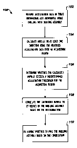
9 Fig. 3 shows an impulse analysis technique 100 according to the
present disclosure in which impulse of the drilistring 14 is calculated and
used to
11 determine whether the drilling assembly 16 is drilling inefficiently and
needs to be
12 pulled out. The tool 20 of Fig. 2 using the sensor unit 30 measures
acceleration
13 data in three orthogonal axes downhole while drilling with the drilling
assembly 16
14 (Block 102). Using the acceleration data, impulse to the drillstring 14 in
at least one
direction (i.e. axial, lateral, both, or a total of both) is calculated over
an acquisition
16 period (Block 104), and a determination is made whether the calculated
impulse
17 exceeds a predetermined acceleration threshold for the acquisition period
(Block
18 106). In one implementation, the predetermined acceleration threshold is
7g, and
19 the acquisition period is one second, although the particular threshold and
period
can depend on details of a particular implementation.
21 Calculating the impulse involves integrating rectified acceleration data
22 in the at least one direction over the acquisition period. For example, the
impulse
23 can be calculated in one or more of a lateral direction (x and y-axes), an
axial
9
CA 02680942 2009-09-29
1 direction (z-axis), and/or a total of the three orthogonal axes (x, y, and
z) of
2 acceleration data. To calculate impulse, a number of impulse shocks that
exceed
3 the predetermined threshold for the acquisition period can also be counted.
In turn,
4 this impulse shock count can then be used with the impulse value to
calculate an
impulse shock density value that can be used for analysis.
6 Impulse exceeding the threshold is then correlated to the efficiency of
7 the drilling assembly 16 so a determination can be made whether to pull the
drilling
8 assembly 16 (Block 108). Correlating the calculated impulse to efficiency of
the
9 assembly 16 involves determining whether the calculated impulse occurs
continuously over a predefined penetration depth through the formation. The
11 impulse used in the correlation can include the impulse values in one or
more of the
12 lateral, axial, and total directions and can include the impulse shock
count as well
13 as the impulse shock density discussed previously.
14 In one implementation, the predefined penetration depth for
correlating to the drilling assembly's inefficiency is 25 feet through the
formation, but
16 this depth can depend on a number of variables such as characteristics of
the
17 assembly 16, drill bit 19, stabilizers 18, the formation, drilling
parameters, etc. If the
18 calculated impulse does occur continuously over the predefined penetration
depth,
19 a determination is made to pull the drilling assembly 16 (Block 110).
Otherwise, the
assembly 16 is not pulled.
21 In general, the tool 20 of Fig. 2 can perform the calculations and
22 perform the determination using the processor 40 and can transmit the
impulse data
23 to the surface using the mud pulse telemetry system 24, where surface
processing
CA 02680942 2009-09-29
1 equipment 50 can be used to make the correlation and determination to pull
the bit.
2 Alternatively, the tool 20 of Fig. 2A can transmit raw data to the surface
using the
3 mud pulse telemetry system 24, and surface processing equipment 50 can
perform
4 the calculations for making the determination.
A. Calculations
6 Several real-time data items and calculations can be used for
7 analyzing impulse experienced by the drillstring 14 during drilling. The
real-time
8 data items and calculations are provided by the vibration monitoring tool 20
of Figs.
9 1-2. In one implementation, real-time data items can be identified that
cover
acceleration, RPM, peak values, averages, etc. As detailed herein, tracking
these
11 real-time data items along with the impulse calculation values helps
operators to
12 monitor drill bit efficiency and determine when the drill bit needs to be
pulled out.
13 In particular, the tool 20 tracks a number of data items that are used to
14 monitor impulse and shocks to be correlated to inefficiency of the drilling
assembly
16. The tool 20 itself or the processing equipment 50 at the surface can
perform the
16 calculations necessary to determine when to replace portion of the drilling
assembly
17 16, such as a stabilizer 18 or the drill bit 19. The impulse and shocks can
be
18 monitored and calculated in an axial direction, lateral direction, and/or a
total of
19 these two directions as follows:
1. Axial Direction
21 For the axial direction (i.e. z-axis), the calculated data items include
22 the average axial acceleration, the axial impulse, the number of axial
shock events,
23 and the axial impulse shock density (ISD) for an acquisition period. The
average
11
CA 02680942 2009-09-29
1 axial acceleration over a 1-sec acquisition period can be characterized as:
iooo
2 Axial _ Average(1 sec) Z_ inst(l ms)
3 The axial impulse is the integration of the rectified z-acceleration that
4 exceeds the predetermined threshold for the acquisition period. Preferably,
the
threshold is 7g. Accordingly, axial impulse over the 1-sec acquisition period
can be
6 characterized as:
looo
7 Axial _ impluse(1 sec) Z_ inst(lms) > Theshold
8 The axial impulse shock density (ISD) is calculated from the axial
9 impulse and the number of axial shock events that have occurred during the
acquisition period. In other words, the axial shock events are the total
number of z-
11 shocks that have exceed the predetermined threshold of 7g for the 1 second
12 acquisition period. The axial impulse shock density (ISD) is characterized
as:
13 Axial - ISD(1 sec) I_(Axial _ impulse(1 sec))2 *1000
Axial - shockevents(1 sec)
14 For a given impulse energy, the impulse shock density goes down as
the frequency of shocks goes up. The reverse is also true. As the frequency of
16 shocks goes down, the impulse shock density value increases. Therefore, the
17 value of the impulse shock density has a shock frequency component because
18 higher frequency shocks take less energy to produce than lower frequency
shocks.
19 In other words, the more energy that is used to produce the vibration, then
the less
energy can be used to drill the hole. This information can be useful then in
21 analyzing the drilling operation and determining drill bit efficiency.
12
CA 02680942 2009-09-29
1 2. Lateral Direction
2 Calculations for the lateral direction are similar to those discussed
3 above, but use acceleration in the x & y-axes. In particular, the average
lateral
4 acceleration is calculated as:
iooo
Lateral _ Average(i sec) = E (X _ inst(lms))2 + (Y _ inst(1ms))2
1
6 The lateral Impulse is the integration of the rectified lateral (x and y
7 axes) acceleration that exceeds a predetermined threshold of 7g for the 1
second
8 acquisition period. Therefore, the lateral impulse is calculated as:
iooo
9 Lateral - impulse(1 sec) = E (X _ inst(lms))Z + (Y _ inst(lms))z > Theshold
I
In turn, the lateral impulse shock density (ISD) is then calculated from
11 the lateral impulse and number of lateral shock events over the acquisition
period
12 as follows:
13 Lateral _ ISD(1 sec) _(Lateral _ impulse(1 sec))Z *1000
Lateral - shockevents(1 sec)
14 3. Total
Calculations for the total of all directions are similar to those discussed
16 above, but use acceleration in the x, y, & z-axes. In particular, the
average total
17 acceleration is calculated as:
18 In particular, the average total acceleration is calculated as:
i o00
19 Total _ Average(1 sec) = E V(X _ inst(lms))Z + (Y _ inst(1ms))Z + (Z _
inst(lms))2
1
The total Impulse is the integration of the rectified total (x, y, and z
21 axes) acceleration that exceeds a predetermined threshold of 7g for the 1-
sec
13
CA 02680942 2009-09-29
1 acquisition period. Therefore, the total impulse is calculated as:
1000
2 Total _ impulse(1 sec) (X _ inst(l ms))Z + (Y _ inst(lms))2 + (Z _
inst(lms))2 > Theshold
3
4 In turn, the total impulse shock density (ISD) is then calculated from
the total impulse and number of total shock events over the acquisition period
as
6 follows:
7 Total - ISD(1 sec) _(Total _ impulse(1 sec))2 *1000
Total - shockevents(1 sec)
8 As noted previously, the calculated data items can be calculated by
9 the tool 20 downhole and pulsed uphole, or they can be calculated at the
surface by
processing equipment 50 based on raw data pulsed uphole from the tool 20.
11 According to the present techniques discussed above, the calculated
impulses,
12 shocks, and impulse shock density are used to analyze the efFiciency of the
drilling
13 assembly 16 and to determine whether the assembly 16 needs to be pulled.
14 Operators can also use the data items and the calculated impulses, shocks,
and
impulse shock density to analyze the drilling efficiency so that drilling
parameters
16 can be changed accordingly.
17 As noted above in the calculations, the impulse is the integration of
18 acceleration above a predetermined threshold during an acquisition period.
Shocks
19 are the number of vibration events that exceeded a predetermined threshold
during
the acquisition period. In the present implementation, the predetermined
threshold
21 is defined as an acceleration of 7g, and the acquisition period is one (1)
second.
22 However, these values may vary depending on a particular implementation.
14
CA 02680942 2009-09-29
1 B. Log
2 Figs. 4A-41 show a log showing exemplary logging information for
3 several runs. Some of the plotted logging information, including impulse
data, is
4 obtained from the vibration monitoring tool (20; Figs. 1-2) while drilling.
The log
includes typical data such as block height, bit's rate of penetration (ROP),
and
6 Weight on bit (WOB), torque, stick slip alert (SSA), drilling rate of
penetration
7 (DEXP), and mechanical specific energy (MSE), as well as average, max, and
min
8 downhole RPM and surface RPM-each of which is plotted vertically with depth.
9 Also, the impulse (lateral in this example) is plotted with depth.
During drilling, the impulse data (axial, lateral, and total impulse data,
11 shock data, and impulse shock density) is calculated at the tool (20; Figs.
1-2) and
12 pulsed to the surface. Recalling that the impulse data is triggered based
on a
13 predetermined threshold within an acquisition period, the impulse data of
particular
14 consideration may not be sent to the surface, whereas other data from the
tool (20)
may. When impulse data is encountered and sent to the surface, however, it is
16 correlated as a function of reduced performance or efficiency of the
drilling
17 assembly as described herein to indicate to operators that the assembly is
no
18 longer functioning effectively and needs to be pulled.
19 In one particular implementation, for example, the impulse algorithm
determines when the triggered impulse data has occurred over a continuous
drilling
21 length of 25 feet or so. If this happens, the algorithm assumes at this
point that the
22 drilling assembly 16 is no longer drilling efficiently and that it is time
to pull the
23 assembly 16 out to replace or repair its components, such as a stabilizer
18 or drill
CA 02680942 2009-09-29
1 bit 19. If the impulse data is not encountered for that continuous length,
then the
2 operator may not need to pull the assembly 16 out because it still may be
effective.
3 In this case, the algorithm would not indicate that the drilling assembly 16
needs to
4 be pulled.
In the sections of the log marked "RUN 1" and "RUN 2," for example,
6 operators drilled without the benefit of the real-time impulse data for
determining
7 whether to pull the drilling assembly out or not. In both of these runs,
operators
8 continued drilling to the extent that the drill bit was damaged beyond
repair. If the
9 operators had the benefit of the real-time impulse data and calculations of
the
present disclosure, the ineffectual progress in drilling and unrepairable
damage to
11 the drill bit could have been avoided and/or reduced in severity because
the real-
12 time impulse data and calculations would have indicated to the operators to
pull the
13 assembly at a more appropriate time.
14 In the section of the log marked "RUN 4," for example, a continuous
25 feet of impulse data was not encountered. Therefore, the operators did not
need
16 to pull the drilling assembly 16 so early during this run. As a result,
pulling the
17 assembly out too soon can waste considerable amount of rig time. Although
the
18 above log has been discussed with reference to the efficiency of the drill
bit, the
19 determination of when other components of the drilling assembly, such as
stabilizers or the like, have experienced damage to the extent of no longer
being
21 effective is similar to that applied to the drill bit.
16