Language selection

Search

Patent 2680957 Summary

Third-party information liability

Some of the information on this Web page has been provided by external sources. The Government of Canada is not responsible for the accuracy, reliability or currency of the information supplied by external sources. Users wishing to rely upon this information should consult directly with the source of the information. Content provided by external sources is not subject to official languages, privacy and accessibility requirements.

Claims and Abstract availability

Any discrepancies in the text and image of the Claims and Abstract are due to differing posting times. Text of the Claims and Abstract are posted:

  • At the time the application is open to public inspection;
  • At the time of issue of the patent (grant).
(12) Patent: (11) CA 2680957
(54) English Title: A METHOD FOR CONTROLLING A STATIC POWER CONVERSION UNIT AND INDUCTION HEATING SYSTEM FOR COOKING APPLIANCES USING SUCH METHOD
(54) French Title: METHODE DE CONTROLE D'UNITE STATIQUE DE CONVERSION D'ENERGIE ET DE SYSTEME DE CHAUFFAGE PAR INDUCTION, POUR APPAREILS DE CUISSON UTILISANT CES TECHNOLOGIES
Status: Granted and Issued
Bibliographic Data
(51) International Patent Classification (IPC):
  • H05B 06/06 (2006.01)
  • H05B 06/12 (2006.01)
(72) Inventors :
  • GUTIERREZ, DIEGO NEFTALI (Italy)
  • SANTACATTERINA, GIANPIERO (Italy)
  • PADERNO, JURIJ (Italy)
(73) Owners :
  • WHIRLPOOL CORPORATION
  • TEKA INDUSTRIAL S.A.
(71) Applicants :
  • WHIRLPOOL CORPORATION (United States of America)
  • TEKA INDUSTRIAL S.A. (Spain)
(74) Agent: SMART & BIGGAR LP
(74) Associate agent:
(45) Issued: 2017-05-02
(22) Filed Date: 2009-09-29
(41) Open to Public Inspection: 2010-04-08
Examination requested: 2014-09-24
Availability of licence: N/A
Dedicated to the Public: N/A
(25) Language of filing: English

Patent Cooperation Treaty (PCT): No

(30) Application Priority Data:
Application No. Country/Territory Date
08166091.2 (European Patent Office (EPO)) 2008-10-08

Abstracts

English Abstract

In a method for controlling a static power conversion unit to an inductor, particularly for an induction system used in cooking appliances, the value of an electrical parameter of the circuit is monitored at predetermined time intervals (.DELTA.t1) and at a predetermined duty cycle of the power transistor switching frequency, and on the basis of said monitored value, the duty cycle is modulated accordingly between said predetermined time intervals in order to keep the delivered power at a predetermined constant value.


French Abstract

Dans un procédé pour commander un ensemble de conversion de puissance à un inducteur, particulièrement pour un système dinduction utilisé dans des appareils de cuisson, la valeur dun paramètre électrique du circuit est surveillée à des intervalles de temps prédéterminés (.DELTA.t1) et à un cycle dutilisation prédéterminé de la fréquence de commutation de transistor de puissance, et en fonction de ladite valeur surveillée, le cycle dutilisation est modulé en conséquence entre lesdits intervalles de temps prédéterminés afin de maintenir la puissance délivrée à une valeur constante prédéterminée.

Claims

Note: Claims are shown in the official language in which they were submitted.

6
We claim:
1. A method for controlling a static power conversion unit delivering power
to an
inductor for an induction system used in cooking appliances, the method
comprising:
monitoring a value of an electrical parameter of a circuit at predetermined
time
intervals and at a predetermined duty cycle of a power transistor;
modulating the duty cycle, based on the value, between the predetermined time
intervals in order to keep the power at a predetermined constant value; and
changing a drive frequency of the power transistor during operation of the
inductor according to a predetermined time pattern.
2. The method according to claim 1, wherein the electrical parameter is
dependent
on temperature.
3. The method according to claim 1, wherein changing the frequency during a
cooking process prevents a non-optimal working condition or occurs as a
consequence
of a detected external event.
4. The method according to claim 1, wherein changing the drive frequency
occurs
at predetermined times which encompass several predetermined time intervals.
5. The method according to claim 1, wherein modulating the duty cycle of
the power
transistor drive frequency keeps constant a current that flows through an
induction coil.
6. An induction heating system, particularly for cooking appliances,
comprising:
a power supply unit for delivering power to an inductive coil; and
a control unit for controlling the power at a predetermined level, wherein the
control unit is adapted to measure a value of an electrical parameter of the
power

7
supply unit at predetermined time intervals and at a predetermined duty cycle
of
a power transistor, the control unit being also being adapted to modulate the
duty
cycle between the predetermined time intervals in order to keep the power at a
predetermined level wherein a drive frequency of the power transistor is
changed
during a cooking process according to a predetermined time pattern.
7. The induction heating system according to claim 6, wherein the
electrical
parameter is dependent on temperature.
8. The induction heating system according to claim 6, wherein the drive
frequency
is changed during the cooking process in order to prevent a non-optimal
working
condition or as a consequence of a detected event.
9. The induction heating system according to claim 6, wherein the drive
frequency
is changed at predetermined times which encompass several predetermined time
intervals.
10. The induction heating system according to claim 6, wherein the
modulation of the
duty cycle of the power transistor is done in order to keep a current that
flows through
the inductive coil constant.
11. A method of controlling a static power conversion unit in an induction
heating
system having an inductive coil arranged in a cooking appliance to provide for
a cooking
process, the method comprising:
monitoring at predetermined time intervals a value of an electrical parameter
associated with a circuit connecting the static power conversion unit to the
inductive coil;
providing power from the static power conversion unit to the inductive coil at
a
power

8
transistor switching frequency and at a predetermined duty cycle;
modulating the duty cycle based on the value of the electrical parameter
between
the predetermined time intervals to maintain the power at a predetermined
constant value; and
varying a power transistor drive frequency during the cooking process.
12. The method according to claim 11, wherein the electrical parameter is
dependent
on temperature.
13. The method according to claim 11, further comprising changing the power
transistor drive frequency during the cooking process according to a
predetermined time
pattern.
14. The method according to claim 13, further comprising changing the power
transistor drive frequency at predetermined times which encompass several
predetermined time intervals.
15. The method according to claim 11 further comprising modulating the duty
cycle
to maintain a constant current through the inductive coil.

Description

Note: Descriptions are shown in the official language in which they were submitted.


CA 02680957 2016-04-29
1
A METHOD FOR CONTROLLING A STATIC POWER CONVERSION
UNIT AND INDUCTION HEATING SYSTEM FOR COOKING
APPLIANCES USING SUCH METHOD
This application claims priority on EP Patent Application No.
08166091.2 filed October 8, 2008.
The present invention relates to a method for controlling the
power delivered by a static power conversion unit to an inductor,
particularly for an induction heating system used in cooking appliance.
The present invention relates as well to an induction heating system,
particularly for cooking appliances, adapted to carry out such method.
It is well known in the art of induction heating systems used in
cooking appliances the importance of controlling the power delivered
by the inductor, i.e. the induction coil, in order to adjust the cooking
temperature or the cooking utensil heating level at a predetermined
level. This is usually obtained by modifying the power transistor
switching frequency. For an improved cooking performance it is
important to sense the cooking vessel's temperature during the whole
process. This information could be used e.g. to control said
temperature or to monitor the cooking process phase.
EP-A-1732357 discloses an induction heating device in which
the pot's temperature variations are monitored by adjusting the
power transistor drive frequency throughout the cooking process in
the induction heating. According to such document, during the
cooking process the static power conversion unit (converter) operates
in two ways: during "heating" intervals it controls the frequency in
order to guarantee constant power; during "measurement" intervals,
it keeps the frequency to a fixed constant value and measures an
electrical parameter correlated to the temperature of the pot bottom.
The above known solution needs that the induction converter
changes the frequency of the power transistor drive signal. This
requires finding at least two suitable frequencies adapted for the pot
load. The choice of the frequencies must be done with special care in
order to avoid problem of pan detection (in case one of the

CA 02680957 2009-09-29
2
frequencies is too high) and/or resonance (coil current might be too
big, which is dangerous for the induction power components like the
insulated-gate bipolar transistor and which may lead to a failure of the
whole induction heating system).
It is an object of the present invention to provide a control
method which overcomes the above drawbacks of the known
solutions.
According to the invention, such object is reached thanks to the
features listed in the appended claims.
The basic idea underlying the present invention is to avoid the
above problems by acting directly on the duty cycle value. In this case
the frequency remains always the same, the control of power and the
measurement of the induction converter electrical parameter are
accomplished with a pulse-width modulation (PWM) methodology by
varying the duty cycle of the power transistor drive signals, with the
final object of monitoring the temperature of the cooking vessel.
This minimizes the risk of changing the frequency continuously,
since the selection of the frequency is done at the beginning of the
control algorithm.
Further features and advantages of a method and of an induction
heating system according to the present invention will be clear from
the following detailed description, with reference to the attached
drawings, in which:
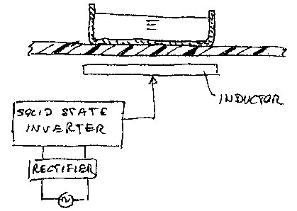
Figure 1 is a schematic view of an induction heating system
used in a cooktop;
Figure 2 is a schematic view of a typical topology for the
induction heating half bridge series-resonant converter which
can be used in the system of Figure 1, and in which it is shown
how the power/temperature control is carried out;
Figure 3 is a diagram showing the difference between the actual
delivered power vs. time and the power measured during the
"measurement" intervals;

CA 02680957 2009-09-29
3
Figure 4 is a diagram showing a further embodiment of the
invention; and
Figure 5 is a diagram similar to figure 4 in which the frequency
value is changed due to a certain event.
According to a preferred embodiment of the invention,
throughout the cooking process the controller doesn't change the
frequency, rather the duty cycle only. During the "measurement"
intervals At1 (figure 2) it adjusts the duty cycle value to a fixed one,
and during the "heating" intervals At2 it controls and modulates the
duty cycle value so as to keep constant the output power.
At the "measurement" intervals al the control measures at
least one electrical parameter that depends on the power transistor
switching frequency and the duty cycle (both constant between
different Ati), as well on the pot bottom temperature. This can be e.g.
the current flowing through the induction coil, the inductance of the
heating system, the voltage supplied to the coil, the converter output
active power or a combination thereof. Other electrical parameters can
be used as well. At the "heating" intervals At2, induction converter
controls the output power supplied to the pot by modulating the duty
cycle and maintaining the frequency constant.
The converter measures the output power supplied to the pot
during the "measurement" and "heating" intervals and corrects the
duty cycle in order to guarantee a constant output power throughout
the cooking process.
For the description of the invention has been considered an
induction heating converter that controls the output power supplied to
the pot. However, in the market can be found induction heating
converters that control the current that flows through the coil. The
invention can be applied also to these converters as well, and the duty
cycle is modified during the "heating" time so as to keep constant the
coil current amplitude during the whole cooking process.

CA 02680957 2009-09-29
4
In the upper portion of Figure 2 it is shown a diagram power vs.
time showing how the control of the induction heating converter
measures the actual delivered power at "measurement" intervals M1
with a fixed duty cycle, while it modulates the duty cycle in the
"heating" intervals At2. The bottom part of Figure 2 shows a typical
layout of an half bridge series-resonant converter to which the
fixed/modulated pattern of duty cycle according to the invention is
applied. Of course other type of resonant converters can be used as
well.
Figure 3 shows an example of a cooking process: the upper line
in the power vs. time diagram represents the total output power
measured at converter, taking into consideration both "measurement"
intervals Ati and "heating" At2 intervals (it is the actual average power
supplied to the pot). The lower line in the diagram represents the
output power measured during the "measurement" intervals At1. It
shows the inverse relationship with the temperature of the pot
bottom.
According to a second embodiment of the invention, the
technical solution of applying variable asymmetry duty cycles can be
combined with a control that uses "n" different power transistor drive
signal frequencies.
In Figure 4 it is shown an asymmetrical duty cycle control
applied within several "frames" of n-different frequencies of power
transistor drive signal.
The advantages of combining modulated asymmetrical duty cycles
together with different frequencies "frames" is mainly to increase the
robustness of the pot temperature estimation, since it increases the
correlation data between the electrical parameter and the pot bottom
temperature at different duty cycles and frequencies.
Also, this embodiment would increase the compatibility between
the asymmetrical duty cycle and the present standard power/current
closed-loop control that changes the power transistor frequency vs.
time.

CA 02680957 2009-09-29
In Figure 5 it is shown an asymmetrical duty cycle control that
changes the constant frequency value due to internal or external
event that changes the working conditions and prevent the induction
heating converter from working in non-optimal conditions for
5 monitoring the pot temperature. For instance, an internal event might
be variation of the control set point due to temperature derating of
critical hardware component. An external event might be displacement
of the pot placed by the user onto the hob.

Representative Drawing
A single figure which represents the drawing illustrating the invention.
Administrative Status

2024-08-01:As part of the Next Generation Patents (NGP) transition, the Canadian Patents Database (CPD) now contains a more detailed Event History, which replicates the Event Log of our new back-office solution.

Please note that "Inactive:" events refers to events no longer in use in our new back-office solution.

For a clearer understanding of the status of the application/patent presented on this page, the site Disclaimer , as well as the definitions for Patent , Event History , Maintenance Fee  and Payment History  should be consulted.

Event History

Description Date
Maintenance Request Received 2024-09-03
Maintenance Fee Payment Determined Compliant 2024-09-03
Common Representative Appointed 2019-10-30
Change of Address or Method of Correspondence Request Received 2018-01-12
Grant by Issuance 2017-05-02
Inactive: Cover page published 2017-05-01
Inactive: Final fee received 2017-03-13
Pre-grant 2017-03-13
Letter Sent 2016-10-06
Notice of Allowance is Issued 2016-10-06
Inactive: Q2 passed 2016-10-04
Inactive: Approved for allowance (AFA) 2016-10-04
Amendment Received - Voluntary Amendment 2016-04-29
Inactive: S.30(2) Rules - Examiner requisition 2015-11-03
Inactive: Report - QC passed 2015-10-28
Letter Sent 2014-10-08
Request for Examination Received 2014-09-24
Request for Examination Requirements Determined Compliant 2014-09-24
All Requirements for Examination Determined Compliant 2014-09-24
Application Published (Open to Public Inspection) 2010-04-08
Inactive: Cover page published 2010-04-07
Inactive: IPC assigned 2010-03-08
Inactive: First IPC assigned 2010-03-08
Inactive: IPC assigned 2010-03-08
Inactive: Declaration of entitlement - Formalities 2009-12-02
Reinstatement Requirements Deemed Compliant for All Abandonment Reasons 2009-11-03
Application Received - Regular National 2009-10-30
Inactive: Filing certificate - No RFE (English) 2009-10-30

Abandonment History

There is no abandonment history.

Maintenance Fee

The last payment was received on 2016-09-07

Note : If the full payment has not been received on or before the date indicated, a further fee may be required which may be one of the following

  • the reinstatement fee;
  • the late payment fee; or
  • additional fee to reverse deemed expiry.

Patent fees are adjusted on the 1st of January every year. The amounts above are the current amounts if received by December 31 of the current year.
Please refer to the CIPO Patent Fees web page to see all current fee amounts.

Owners on Record

Note: Records showing the ownership history in alphabetical order.

Current Owners on Record
WHIRLPOOL CORPORATION
TEKA INDUSTRIAL S.A.
Past Owners on Record
DIEGO NEFTALI GUTIERREZ
GIANPIERO SANTACATTERINA
JURIJ PADERNO
Past Owners that do not appear in the "Owners on Record" listing will appear in other documentation within the application.
Documents

To view selected files, please enter reCAPTCHA code :


To view images, click a link in the Document Description column. To download the documents, select one or more checkboxes in the first column and then click the "Download Selected in PDF format (Zip Archive)" or the "Download Selected as Single PDF" button.

List of published and non-published patent-specific documents on the CPD .

If you have any difficulty accessing content, you can call the Client Service Centre at 1-866-997-1936 or send them an e-mail at CIPO Client Service Centre.


Document
Description 
Date
(yyyy-mm-dd) 
Number of pages   Size of Image (KB) 
Abstract 2009-09-28 1 19
Description 2009-09-28 5 200
Claims 2009-09-28 2 79
Drawings 2009-09-28 2 98
Representative drawing 2010-03-10 1 17
Description 2016-04-28 5 196
Claims 2016-04-28 3 106
Confirmation of electronic submission 2024-09-02 3 77
Filing Certificate (English) 2009-10-29 1 155
Reminder of maintenance fee due 2011-05-30 1 114
Reminder - Request for Examination 2014-06-01 1 116
Acknowledgement of Request for Examination 2014-10-07 1 175
Commissioner's Notice - Application Found Allowable 2016-10-05 1 164
Correspondence 2009-10-29 1 19
Correspondence 2009-12-01 2 57
Examiner Requisition 2015-11-02 5 266
Amendment / response to report 2016-04-28 8 257
Final fee 2017-03-12 1 53