Note: Descriptions are shown in the official language in which they were submitted.
CA 02681082 2011-05-19
-1-
Optical system for a confocal microscope
Description
The invention relates to an optical system for a confocal microscope.
Various types of 3D scanners exist which capture a surface of an object being
scanned due to the fact that the surface is located focussed. Examples of such
systems are laser confocal microscopes as are known from US2007/0109559
Al or pOFPT as is described in the CH patent application 016247/07.
Known furthermore in prior art are optical systems as briefly discussed in the
following.
DE 10 2005 013 949 Al relates to a scanner for spot focussing a pencil beam,
namely a parallel beam. In this scanner - not intended for use on a confocal
microscope, and thus not required to satisfy exceptionally high demands on the
imaging optics - an optical element located most distal from the object being
scanned is shifted for focussing.
US 2002/0167723 Al relates to a confocal microscope for scanning objects
having a very small height, for example 0.1 mm, in the scanning direction,
this
being the reason why there is no problem as regards the optics with this
confocal microscope. Problems regarding the optics materialize, however, when
objects having a height of, for example, 10 mm need to be scanned, as
explained further on.
EP 1 746 448 A2 relates to a microscope objective, the microscope concerned
not being a confocal microscope and thus the demands on its optics are not so
high. With a positioner serving to compensate the effects of changing
temperatures a focus is varied over just a very small range.
CA 02681082 2011-05-19
-2-
WO 2008/10 1605 Al relates to a confocal laser microscope in which
positioning a lens corrects the color abberation of the optics. Adjusting the
3D
scan is done elsewhere, there being an indication in the description that 3D
shifting the object is possible.
WO 2005/09 1046 Al relates to an intraoral scanner featuring a movable lens
proximal to the object.
It is understood that õobject" as referred to above and hereinafter always has
the meaning of an object to be scanned and imaged.
To implement 3D scanning the focus must pass through the object. Depending
on the application concerned this can be done by moving the object or shifting
the complete device or its optical system relative to the object or by
shifting at
least one element in the optical system.
To scan objects having a height of 10 mm, for example, the scanning depth
may greatly exceed the 3D resolution of the optical system, resulting in the
optics of the optical system needing to satisfy higher demands than, for
example, the scanner as recited in the aforementioned document US
2002/0167723 Al which only needs to be designed to scan objects of very low
height.
Common to all of these systems is that very high demands are made on the
imaging quality. To precisely 3D capture the object, the size of a spot must
be
very small. Ideally the optics should have limited diffraction, i.e. furnish
the
theoretically possible accuracy. But, in some practical applications spot
sizes of
approx. 5 pm (RMS spot radius) need to be satisfied which still makes for an
exceedingly high demand.
CA 02681082 2011-05-19
-3-
In some systems (e.g. parallel confocal microscope or pOFPT) the whole
surface is scanned simultaneously, thus requiring the imaging quality to be
very
good over the whole surface, adding again to the demands on the device.
On top of this, the numerical aperture NA of such devices must need to be
relatively large at the object end to obtain a good 3D resolution. This too,
adds
to the demands on the optical system.
This is why whenever possible the optical system is not varied and either the
object or the whole device or its optical system is moved relative to the
object
during scanning. It is already very difficult to produce an optical system
having
the accuracy as required at a focal plane, but it is even more difficult to
achieve
the wanted imaging quality in all focal positions when lenses are moved in the
optical system.
Should, nevertheless, an element need to be shifted in the optics the typical
approach is to use an infinitely corrected optics by shifting the lens most
proximal to the object as is already known from the aforementioned document
WO 2005/09 1046 Al to thus tweak the focus with no major problem whilst
imaging quality (distortions, magnification, crisp imaging) remains roughly
the
same in all focal planes.
One such optical system is shown in FIG. 1 by way of an example of prior art.
This optical system comprises an illumination pattern 1, a beam splitter 2, a
detector 3 and a first lens 4 at the illumination pattern 1 end and a second
lens
5 at the object 6 end. Rays of light from the illumination pattern 1 pass
through
the beam splitter 2 in the direction of the object 6 through the first lens 4
and the
second lens 5 to a focal plane 7 on the object 6. The light rays reflected
back
from the object 6 pass through the lenses 5, 4 and are deflected at the beam
splitter 2 in the direction of the detector 3 where an image of the object 6
is
detected.
CA 02681082 2011-05-19
-4-
Where a laser confocal microscope is concerned the illumination pattern 1
consists of at least one source of a light spot, the laser and where a pOFPT
device is concerned the illumination pattern 1 consists of an image which is
beamed through by a source of light.
The arrow above the second lens 5 indicates movement of the second lens 5
resulting in a corresponding movement of the focal plane 7 at the object 6 as
indicated by a dashed arrow. The various positions of the second lens 5 and
the
corresponding positions of the focal plane 7 are indicated in FIG. 1 by the
reference numerals 5a and 7a, 5b and 7b and 5c and 7c. To produce the
movement of the second lens 5 a drive is provided which, for example, may be
a controlled motor.
However, in some applications this approach has a serious drawback. For
example, where a dental intraoral scanner is concerned, the optics inserted
into
the mouth of the patient need to be highly compact. But when the second lens
at the object end is configured such that it is provided movable for shifting
the
focal plane, the scanner at the object end, and thus in the mouth of the
patient
must be configured larger to accommodate the movement of the lens and its
drive, resulting in such a scanner just at the end where it is needed as
compact
as possible being larger in size. Achieving a more compact configuration with
a
movable lens at the object end is only possible with great difficulty and is
correspondingly expensive.
It is thus the object of the present invention to provide an optical system
for a
confocal microscope which, especially at the object end being scanned and
imaged, is configured compact.
This object is achieved by the optical system as described hereinafter.
In accordance with the invention an optical system for confocal microscope
comprises an illumination pattern irradiating an object with light rays
reflected
CA 02681082 2011-05-19
-5-
thereby, a beam splitter for passing the light rays from the illumination
pattern in
the direction of the object and for deflecting the light rays reflected by the
object
in a focal plane in the direction of a detector for detecting an image of the
object, and a lens assembly between the beam splitter and the object, at least
one lens of the lens assembly being arranged movable for shifting the focal
plane at the object, and is particularly configured such that at least one
lens of
the lens assembly is an aspherical lens and the movable lens of the lens
assembly is located distal from the object. This now makes it possible to
achieve a compact configuration of the optical system proximal to the object.
Preferably an aspherical lens is employed as the movable lens of the lens
assembly.
The lens assembly comprises preferably the movable lens and at least one non-
movable lens located proximal to the object. Additionally the lens assembly
comprises beam guidance means with non-movable lenses.
More specifically a configuration of the lenses is computed by means of a
optimization program for optical lenses such that a spot size for all spots in
an
image is minimized for all focal planes, it being sufficient when this is done
for
11 spots in the image and at three different focal planes. The optimization
program for optical lenses to obtain a minimum spot size preferably undertakes
imaging of the object on a curved surface for each focal plane as an
aspherical
surface.
One of the non-movable lenses in the optical system is preferably a lens of
highly refractive material and configured very thick, the glass of the thick
lens
preferably being highly refractive material with a refractive index exceeding
1.7
and more than 25 mm thick so that the actual geometrical length of the optics
is
more than 12.5 mm longer than the optical length of the optics.
CA 02681082 2011-05-19
-6-
Preferably the scanning depth is at least 100 times the 3D resolution, a
factor of
200 between 3D resolution and scanning range materializing, for example, with
a relatively high 3D resolution of approx. 50 pm for a height of approx. 10 mm
to
be scanned.
Correcting distortion of scanned surfaces of the object can be done by
compensation computations, possibly as computed by an optimization program
or by calibration measurement.
The optical system in accordance with the invention is particularly suitable
for
use in intraoral dental scanning. The intraoral scanner comprises more
specifically a proximal portion for insertion into the mouth of a patient and
a
distal portion remote from the mouth of the patient, the proximal portion
being
configured slim and compact and the movable lens being arranged in the distal
portion.
These and further features and details of the invention will become clearer to
the person skilled in the art from the following detailled description with
reference to the attached drawings showing features of the present invention
by
way of example in which:
FIG. 1 is a view of an optics for a confocal microscope as proposed in prior
art,
FIG. 2 is a view of an optics for a confocal microscope as proposed in
accordance with the present invention,
FIG. 3 is a view of the compensation principle used in the present invention.
The present invention will now be explained in detail by way of a preferred
embodiment with reference to FIGs. 2 and 3.
CA 02681082 2011-05-19
-7-
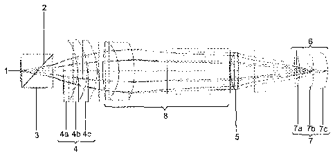
Referring now to FIG. 2 there is illustrated the basic configuration of an
optical
system for a confocal microscope in accordance with the present invention.
Like
the optical system as shown in FIG. 1 for a prior art confocal microscope the
optical system for a confocal microscope in accordance with the present
invention as shown in FIG. 2 consists of an illumination pattern 1, a beam
splitter 2, a detector 3, a first lens 4 at the illumination pattern 1 end and
a
second lens 5 at the object 6 end. In addition to the optical system as shown
in
FIG.1 the optical system as shown in FIG. 2 comprises furthermore beam
guidance means 8 with non-movable lens between the first lens 4 and the
second lens 5. The beam guidance means 8 now make it possible to configure
the optical system long and slim despite the larger numerical aperture NA at
the
object end. This is particularly because one of the lenses used is very thick
and
the glass is formulated with a very high refractive index. To achieve the
necessary imaging quality preferably at least one of the optical systems is
likewise configured aspherical. Thus in the optical system as shown in FIG. 2
the rays pass from the illumination pattern 1 through the beam splitter 2 in
the
direction of the object 6 through the first lens 4, the beam guidance means 8
and the second lens 5 up to a focal plane 7 at the object 6. Unlike the
optical
system as shown in FIG. 1 in the optical system as shown in FIG. 2 the first
lens
4 distal from the object is moved through three different positions of the
first
lens 4, each identified 4a, 4b and 4c. In accordance with the movement of the
first lens 4 the focal plane 7 at the object 6 is shifted to positions
identified 7a,
7b and 7c. For moving the first lens 4 a drive (not shown) is used which may
be
a controlled motor, for example.
The light rays reflected at each focal plane 7a, 7b and 7c pass through the
lens
assembly 4, 5, 8 and are deflected at the beam splitter 2 in the direction of
the
second lens 5 where the image of the object 6 is detected in the focal plane
7.
To attain the necessary imaging quality in all focal planes 7a, 7b and 7c
especially the following precautions are taken:
CA 02681082 2011-05-19
-8-
Aspherical lenses are given preference which recently have become much less
costly and with much better precision to produce than hithertofor since they
can
now even be pressed, resulting in such lenses in mass production being no
more expensive substantially than the classic spherical lenses.
Computing the lenses is done with an optimization program for optical lenses.
With this optimization program especially the size for all spots in the image
is
minimized for all focal planes. In implementing optimization it has been
discovered that it is sufficient to minimize the spot size at 11 different
spots in
the image and at three different focal planes.
With the optimization program the illumination pattern 1 is furthermore imaged
on a curved surface, the shape of which may be freely optimized by the
optimization program to obtain small spot sizes where possible. The focal
plane
is thus not actually a plane but an optionally curved surface, an aspherical
surface likewise being selected for the focal plane.
For each position of the focal plane 7a, 7b, 7c a separate aspherical surface
is
optimized to attain minimized spot sizes for each position.
A total of three aspherical surfaces now make it possible to achieve spot
sizes
minimized at all positions in the image and at all positions of the focal
plane for
a large numerical aperture NA defined by the aperture angle and refractive
index of a lens.
To render the optical system sufficiently long so that even the rearmost teeth
are reached when used as an intraoral scanner a non-movable lens 5, 8 of the
lens assembly 4, 5, 8 is made of highly refractive material and configured
very
thick. Preferably the refractive index of the glass of the thick lens 5, 8
made of
highly refractive material exceeds 1.7, such as 1.92, for example, and its
thickness exceeds 25 mm, such as 31.5 mm, for example. An aperture angle is
preferably selected larger than 20 , the actual geometrical length of the
optics
CA 02681082 2011-05-19
-9-
then being 12.5 mm longer than the optical length of the optics because of the
law of refraction. With example values of 1.92 for the refractive index and
31.5
mm for the thickness of a non-movable lens 5, 8 an optical length by the law
of
refraction is then 31.5 mm / 1.92 = 14.4 mm. But an actual geometrical length
of
the optics amounts to 31.5mm. The optics can thus now be made longer by
approx. 15 mm which is sufficient for scanning even the rearmost teeth in the
mouth of the patient. Without this special configuration the optical system
would
have been either shorter, thicker or less accurate or would have no longer
permitted such a large numerical aperture.
The optical system of the present invention now makes it possible to scan body
surfaces with high accuracy by the optics being designed to advantage.
The drawback in this arrangement is that the scanned surfaces appear
distorted. Flat surfaces appear curved, straight lines appear unstraight.
Apart
from this, the magnifications and curvatures at each position in the image
differ.
However, modern computers now make it possible without any complication to
compensate such distortions since they are totally reproducible.
The theoretical distortions are known, since the shape of the image surface
was, of course, computed by the optimization program, the result of which can
be made use of to compensate the distortions. It is more specifically
preferred,
however, to also scan the distortion and to then compensate it. Such
distortion
compensation is illustrated, for example, in FIG. 3.
When compensating by scanning the distortion it is good practice to proceed as
follows:
First the flat surfaces are scanned which appear curved after scanning.
CA 02681082 2011-05-19
-10-
Then the curvature at each position of an object is scanned. In subsequent
scanning each value is then retrocorrected by this curvature. The curvatures
can be mapped and approximated by a mathematical function such as e.g. a
polynome.
After this, plates having straight lines are scanned, the results of which are
firstly corrected to eliminate the curvature (see above) before then
determining
the shape of the lines which are then corrected the same as the surface
curvatures (mapped or function approximated).
The present invention features an optical system for a confocal microscope in
which a focal plane is shifted by moving a lens. In accordance with the
invention
the movable lens is especially located as far distal as possible to thus
achieve a
compact proximal configuration of the optical system. More specifically, the
optical system can be put to use for intraoral dental scanning without any
increase in the dimensions of the scanner in the mouth of a patient.