Note: Descriptions are shown in the official language in which they were submitted.
CA 02681315 2009-09-14
[DESCRIPTION]
[Invention Title]
ELECTROCHEMICAL BIOSENSOR MEASURING SYSTEM
[Technical Field]
The present irivention relates to an electrochemical
biosensor measuring device.
[Background Art]
F'or_ the diagriosis and prophylaxis of diabetes mellitus,
the importance of periodically monitoring blood glucose levels
is increasingly emphasized. Nowadays, strip-type bioserisors
designed to be used in hand-held reading devices allow
individuals to readily monitor glucose levels in blood.
A large number of commerci_alized biosensors measure the
blood glucose content of blood samples using an
electrochemical technique. The principle of the
electrochemi_cal technique is based on the following Reaction
1. .
[Reaction 1.]
Glucose + GOx-FAD -> gluconic acid + GOx-FADH2
GOx-FADH2 + MoX --> GOx-FAD + Mrect
1
CA 02681315 2009-09-14
wherein, GOx represents glucose oxidase; GOx-FAD and GOx-
FADH2 respectively represent an oxidized and a reduced state of
glucose-associated FAD (flavin adenine dinucleotide), a
cofactor required for the catalysis of glucose oxidase; and MoX
and Mred denote the oxidized and reduced states of an electron
transfer mediator, respectively.
The electrochemical biosensor uses as electron transfer
mediators organic electron transfer materials, such as
ferrocenes or their derivatives, quinines or their
derivatives, organic or inorganic materials containing
transition metals (hexaamine ruthenium, polymers containing
osmium, potassium ferricyanide and the like), organic
conducting salts, and viologens.
The principle of measuring blood glucose using the
biosensor is as follows.
Glucose in the blood is oxidized to gluconic acid by the
catalysis of the glucose oxidase, with the cofactor FAD reduced
to FADH2. Then, the reduced cofactor FADH2 transfers electrons
to the mediator, so that FADH2 returns to its oxidized state;
that is, FAD and the mediator are reduced. The reduced
mediator is diffused to the surface of the electrodes. The
series of reaction cycles is driven by the anodic potential
i5 applied at the working electrode, and redox current
2
CA 02681315 2009-09-14
proportional to the level of glucose is measured. Compared to
biosensors based on colorimetry, electrochemical biosensors
(that is, based on electrochemistry) have the advantages of not
being influenced by the turbidity or color of the samples and
allowing the use of wider range of samples, even cloudy ones,
without pretreatment thereof.
Although this electrochemical biosensor is generally
convenient wherl used to monitor and control the amount of
blood glucose, its accuracy is greatly dependent on the lot-
to-lot variation between respective mass-production in which
the biosensors are produced. In order to elimi_nate such
variatiorl, most of the commercialized biosensors are designed
such that a user directly inputs calibratiorl curve
information, which is predetermined at the factory, into a
measuring device capable of reading the biosensor. However,
this method inconveniences the user a great deal and causes
the user to make input errors, thus leading to inaccurate
results.
In order to solve this problem, a method by which the
resistance of each electrode can be adjusted such that the
variations in mass production is corrected (US20060144704A1),
a method in which a coriductor i_s printed in a bar code fashion
on the biosensor strip to record the production information
3
CA 02681315 2009-09-14
(US6814844), a method irl which a connection to a resistor bank
is made (W02007011569A2), and a method by which information is
read by varying resistance through the adjustment of the
length or thickness of each electrode (US20050279647A1) have
been proposed. The methods proposed for the electrochemical
biosensors are all based on a technique in which electrical
variation is read. Furthermore, a method for distinguishing
production lot information by reading the resistivity of a
conductor marked on a strip using an electrical method
(US4714874) has been proposed.
However, these methods function to accurately adjust
resistance, and require a process of mass-producing the
sensors first, measuring the statistical characteristics of
the sensors, and post-processing the measured information
again using a method of adjusting the resistance marked on the
sensors. However, the process of accurately adjusting the
resistance, marked in large quantities, through the post-
processing is very inconvenient, and is difficult to use, in
practical applications.
Methods in which colored marks are used with a spectral
system capable of discriminating colors to realize a
colorimetric method (US3907503, US5597532, US6168957), a
method in which a plurality of color marks is read at various
wavelengths of visible and infrared ray regions using a
spectroscope (US5945341), and a method capable of reading bar
4
CA 02681315 2009-09-14
codes (EP00075223B1, W002088739A1) have been proposed. These
methods using color or bar codes are favorable for a
colorimetric method-based sensor using the spectrum system,
but they have technical and economic difficulties when applied
to a system using an electrochemical measurement mechanism.
For example, the size and structure of a portion where the
electrochemical sensor strip is inserted into the measuring
device for the purpose of electrical connection, that is, a
connection space of the sensor strip, is very limited in
constructing a device and circuit for spectroscopically
identifying a structure into which the production lot
informatiori is input. Further, as shown in FIG. 1, because a
light emitter-detector system is operated in a manner such
that the detector senses the light reflected by or transmitted
through a production lot information identification portion to
which light is projected from photodiodes of various colors, a
process of scattering various wavelengths of the detected
light usirlg a filter is required to identify the information
of the light, which makes the calculation process, the device,
and the program complicated. Thus, the expense for
constructing the system is greatly increased.
Furthermore, instead of the methods of marking the
production lot information on the sensor strip, a method of
recording information on a container or pack containing a
sensor and allowing the information to be read by the
5
CA 02681315 2009-09-14
measuring device (EP0880407B1) has been proposed. However,
this method also has a possibility of causing the user to make
an error in which a code recorded on the container is
incorrectly read.
Leading to the present invention, intensive and thorough
research into electrochemical biosensors, conducted by the
present inventors, aiming to maintain economic efficiency in
the construction of the measuring device while allowing the
mass production of an electrochemical biosensor in which the
so production lot information thereof can be easily and
accurately input into the measuring device and which removes
the risk of mistakes being made by the user, thus providing an
accurate measurement value, resulted iri the finding that, when
the production lot information is recorded on the
electrochemical biosensor strip using infrared
absorption/reflection marks and when a production lot
information identification portion, at which the production
lot information is recorded on the electrochemical biosensor
strip, is identified in the measuring device, there is no need
to use a high-priced filter in the case where photodiodes of
various colors sequentially emit light at regular time
intervals, so that the light emitter-detector system has a
simple construction and is formed on the same printed circui_t
board (PCB) of measuring device, and thus can not only reduce
a complicated calculation process performed for post-treatment
6
CA 02681315 2009-09-14
but also maintain economic efficiency in the construction of
the measuring device.
[Disclosure]
[Technical Problem]
Accordingly, the present invention has been made keeping
in mind the above problems occurring in the prior art, and an
object of the present invention is to provide an
electrochemical biosensor measuring device comprising at least
two light emitters emitting light at regular time intervals
and a detector for sensing the light from the light emitters,
which, when the electrochemical biosensor is inserted into the
measur.ing device without a mistake being made by a user,
automatically identifies the production lot information of the
biosensor, thus enabling blood glucose to be conveniently and
accurately measured and being economical.
[Technical Solution]
In order to accomplish the above object, the present
invention provides an electrochemical. biosensor measuring
device, which measures an electrochemical biosensor composed
of plurality of electrodes including at least a working
electrode and an auxiliary electrode prepared on at least one
or two insulating plates; a capillary sample cell for
introducing a sample into the electrodes; a reaction reagent
7
CA 02681315 2009-09-14
layer, formed on the working electrode, containing a redox
enzyme and an electron transfer mediator; an electrical
connection portion for connecting the working electrode and
the auxiliary electrode; and a production lot information
identificatiori portiori configured such that production lot
information is recorded on at least one insulating plate,
which is selected from among at least two planar insulating
plates and does not interrupt a connection between the
electrodes,
wherein the electrochemical biosensor measuring device
comprises at least two light emitters sequentially emitting
light at regular time intervals and a detector for sensing the
emitted light, so as to identify the production lot
information recorded on the production lot i.nformatiori
identificatiori portion.
In the specification, the term "biosensor" is used to
have the same meaning as the term "biosensor strip".
[Advantageous Effects]
The electrochemical biosensor measuring device according
to the preserlt invention enjoys economic advantages of not
requiring a high-priced optical filter in detecting the light
absorbed through or reflected from the production
identification information recorded in biosensor and a
complicated software algorithm to recover the production lot
8
CA 02681315 2009-09-14
information. Also, the measuring device automatically
identifies the production lot information recorded on the
biosensor, so that the frequency of inconvenience and error
that occur when a user personally inputs the production lot
information of the biosensor can be reduced, with the result
that the measured values can be conveniently and accurately
acquired.
[Description of Drawings]
The above and other objects, features and advantages of
the present invention will be more clearly understood from the
following detailed description taken in conjunction with the
accompanying drawings, in which:
FIG. 1 is a schematic view showing a process of
1~) identifying production lot information on a biosensor on a
conventional electrochemical biosensor measuring device; and
FIG. 2 is a schematic view showing a process of
identifying production lot information on a biosensor on an
electrochemical biosensor measuring device according to an
embodiment of the present invention.
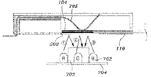
<BRIEF DESCRIPTION OF' THE MARK OF DRAWINGS>
104: electrode
110: biosensor strip
500: production lot information identification portion
9
CA 02681315 2009-09-14
702: light emitter
703: detector
704: printed circui_t board
705: electrical connection portion
[Best Mode]
The electrodes of the electrochemical biosensor used in
the electrochemi_cal biosensor measuring device according to
the present invention may be formed on one or both of at least
two planar insulating plates. That is, (1) a single working
electrode and a single auxiliary electrode (or reference
electrode) may be formed on the same planar insulating plate,
or (2) may be formed on two plariar insulating plates facing
each other [parallel electrodes; reference: E. K. Bauman et
al., Analytical Chemistry, vol 37, p 1378, 1965; K. B. Oldham
in "Microelectrodes: Theory and Applications," Kluwer Academic
Publishers, 1991; J. F. Cassidy et al., Analyst, vol 118, p
4151.
In addition, the electrodes of the electrochemical
21 biosensor used in the electrochemical biosensor measuring
device according to the present invention may further include
a sample fluidity determining electrode that is disposed
behind the working electrode and is capable of measuring the
fluidity of whole blood samples on a lower planar insulating
plate.
CA 02681315 2009-09-14
The biosensor is described in greater detail taking
parallel electrodes as an example.
In the case where the electrochemical biosensor used for
the electrochemical biosensor measuring device according to
the present invention is constructed using the parallel
electrodes, the biosensor may have a structure in which the
working electrode and the auxiliary electrode are spaced apart
from each other by a pressure-adhesive spacer 50-250 pm thick,
and are aligned or not aligned with each other while facing
each other.
In the thin spacer, a capillary sample cell on a
microliter volume scale is provided for injecting a bio-sample
in a measurement space defi.ned by the working electrode and the
auxiliary electrode and retaining the sample therein. The
capillary sample cell includes a sample introducing portion and
a micro-path.
In the thin spacer, a sample fluidity determining
electrode is placed preferably at a predetermined distance from
the working electrode or the auxiliary electrode so that
fluorinated blood having a corpuscle volume of 40% can reach
the working electrode (or the auxiliary electrode) along a
micro-path 0.5-2 mm wide and 50-250 pm high within about 600
ms, and more preferably at a predetermined distance from the
working electrode or the auxiliary electrode such that non-
fluori.nated blood can reach the electrode along the micro-path
11
CA 02681315 2009-09-14
0.5-2 mm wide and 50-250 pm high within 300 ms, and far more
preferably within 200 ms.
Functioning to introduce a blood sample into one end of
the biosensor, the sample-.introducing portion is preferably
formed in a"L" shape so as to allow the rapid, accurate and
convenient introduction of a blood sample from the fore end of
the biosensor strip. The sample introducing portion is
structured such that an allowance space is formed at a
location at which a sample introducing path and an air vent
are crossed. By the term "crossed", as used herein, it is
meant that the sample-introducing path and the air vent are
not arranged parallel to each other, but intersect each other
at a predetermined point.
During measuremerit, the allowance space helps maintain a
constant and accurate volume of the blood sample within the
path while discharging the excess sample through the air vent.
Also, the allowance space may be used as the place where the
sample fluidity determining electrode is disposed. When
introduced into the sample introducing portion, a blood sample
moves to the electrodes through the micro-path.
In the electrochemical biosensor used in the
electrochemical biosensor measuring device accordirig to the
present invention, the reaction reagent layer may formed
merely by applying a reagerit solution only to the working
electrode, or to both the working electrode and the sample
12
CA 02681315 2009-09-14
fluidity determi_ning electrode. The reaction reagent layer
includes ari enzyme, such as a glucose oxidase or a lactate
oxidase, an electron transfer mediator, a water-soluble
polymer, such as a cellulose acetate, a polyvinyl alcohol or a
polypyrrol, a fatty acid having 4 to 20 carbon atoms as a
reagent for reducing a hematocrit effect, and a hydrophilic
quaternary ammonium salt.
In the electrochemical biosensor according to the present
invention, electrode connection portions at which the
biosensor and the measuring device are electrically connected
are designed to exist i.n the same plane in which the working
electrode and auxiliary electrode are connected via connection
lines. The level of blood glucose that is measured by the
biosensor of the present invention from the results of an
electrochemical reaction is provided to the measuring device
through the electrode connection portions, and thus can be
numerical.ly converted into a precise blood glucose value.
The electrochemical biosensor according to the present
invention includes a production lot information identification
portion for providing calibration curve information about
various concentrati_ons of liquid samples, which is used for
respective production lots at the time of manufacturing the
biosensor, along with biosensor production lot information, to
a user.
The production lot information identification portion may
13
CA 02681315 2009-09-14
include one or more hue marks displaying the information about
differences between production lots attributable to
differences in color, brightness, or chroma. It is preferred
that the number of hue marks be adjusted to fall within the
range of 1 to 10.
In the electrochemical biosensor measuring device
according to the present invention, the operational principle
of identifyi_ng the production lot information identification
portion in the measuring device is described in detail below.
In the measuring device, at least two light emitters, for
examples, photodiodes, are integrated within a small space.
Photodiodes useful in the present invention are preferably
three-component light emitting diodes emitting red, blue and
green colors, or four-component light emitting diodes emitting
white, red, blue and blue colors, but are not limited thereto.
The light emitted from the photodiodes is sensed by the
productiorl lot informati_on identification portion of the
biosensor. In this regard, the photodiodes with different
wavelengths are preferably operated at regular time intervals
in a sequential manner.
The light sensed by the production lot irlformation
identificatiorl portion is transmitted therethrough or
reflected therefrom, experiencirig a change in intensity or
wavelength. The transmitted or reflected light is detected by
a detector, such as an optical identifier, set at an
14
CA 02681315 2009-09-14
intermediate location of the light emitters. The change in
the intensity and wavelength of light, as detected by the
detector, is delivered to a calculation system in which the
change is converted irito digital information. The coriverted
digital information is combined to appear as the production
lot information of the biosensor.
The two or more photodiodes emit light beams with
different wavelengths in a sequential manner at regular time
intervals. The light beams, origirlated from the emitters,
containing the production lot information, can be detected in
a sequential. manner by a detector without a filter.
With reference to FIG. 2, a light emitter 700 i_s composed
of three-component photodiodes emitting red (R), green (G) and
blue (B) colors. When it is radiated on a production lot
information identification portion 500, the red light is
transmitted through or reflected from the production lot
information identification portion 500 and sensed by a
detector 703, in which the change in the intensity and
wavelength of the light is converted into digital information.
Next, the green light is also radiated on the production lot
information identification 500 and sensed by the detector 703,
in which the change in the intensity and wavelength of the
light is converted into digital information. Then, the blue
light is also radiated on the production lot information
CA 02681315 2009-09-14
identification 500 and sensed by the detector 703, in which
the change in the intensity and wavelength of the light is
converted into digital information. 'I'he digital information,
obtained by convertirig the light, is combined to provide
productiori lot information as hue marks.
Conventionally, because many photodiodes emit light beams
of various wavelengths simultaneously, which are then sensed
by a detector, a process of scattering and filtering various
wavelengths of the detected light using a spectrometer and a
filter is required to identify the light information, which
makes the calculation process thereof as well as the device
and program thereof complicated. In contrast, the
electrochemical bioserisor measuring device according to the
present _inverltion is operated to emit light beams from
photodiodes in a sequenti.al manner, so that no filtering
processes are required, obviating complicated computation
processes. Thus, the electrochemical biosensor measuring
device according to the present invention can be constructed
to have a simple structure, which is economically favorable.
In add:itiori, with the insertion of the electrochemical
biosensor thereinto, the electrochemical biosensor measuring
device acco.rding to the present invention automatically
identifies the production lot information of the biosensor,
thus enabling blood glucose to be conveniently and accurately
measured without a mistake being made by a user, and being
16
CA 02681315 2009-09-14
economical.
The light emitter and the detector may be constructed in
a separated or integrated structure. The detector may be
located in the same plane as the light emitter when it is
adapted to detect the light reflected from the hue marks, and
may be located in a plane opposite the light emitter when it
is adapted to detect the transmitted light.
The production lot information identification portion
adapted for the electrochemical biosensor, which is used for
the electrochemical biosensor measuring device accordi.ng to
the present invention, is not limited to a parallel type
electrochemical biosensor, and may also be applied to a plane
type electrochemical biosensor, which is implemented such that
the working electrode and the auxiliary electrode are formed
in the same plate and are thus operated, and to a differential
type electrochemical biosensor, which is implemented such that
the parallel type electrochemical biosensor and the plane type
electrochemical biosensor process signals differently.
The electrochemical biosensor measuring devi_ce according
to the present invention may be used along with a connector
having a structure in which one or more absorption or
reflection path(s), comprising light-emitting unit/production
lot informatiori identification portion/detector, can be
realized, thereby identifying the production lot information
17
CA 02681315 2009-09-14
marked on the biosensor.
The conrlector, for example, may be formed of a body
having transparent material, such as transparent acrylic or
plastic.
Furthermore, the connector may be provided with a
transmission window in one side thereof so that infrared rays
absorbed or reflected via the light-emitting unit/production
lot information identification portion/detector are passed
therethrough. Accordingly, even when the connector is made of
opaque material or even when the body of the connector is
colored, the light beams radiated by the light-emitting units
can easily reach the production lot iriforrnation identifi_cat.iori
portion of the biosensor through the transmission window, and
thus the production lot informati_on cari be identi.f.ied.
Furthermore, in order to pass the light beams, which are
absorbed or reflected via light-emitting unit/production lot
information identification portion/detector, through the
connector, the connector may be manufactured such that one
side thereof has a sliding door structure. In greater detail,
when a biosensor is inserted into the connector, the sliding
door structure of the connector is pushed along with the
biosensor i_n the i_nserti_on direction of the biosensor, thus
realizing the path along which the light beams can reach the
production lot information identification portion of the
biosensor. In this case, the sliding door structure may be
18
CA 02681315 2009-09-14
connected to a device that can passively or automatically
remove the biosensor, and thus the biosensor can be easily
separated and removed from the biosensor measuring device
using the removing device after the use of the biosensor.
The light emitting unit and detector used for the
biosensor measuring device according to the present invention
may be located inside or outside the connector of the
measuring device. In greater detail, the light emitting unit
and the detector may be integrated into the connector body, or
may be used as structures that are separate from the connector
body.
F'urthermore, the present invention provides a measuring
method using the electrochemical biosensor measuring device,
comprisirig:
inserting a bioserlsor provided with a production lot
identification portion containing production lot information
into the connector port of the biosensor measuring device to
activate its power (step 1);
identifying the production lot information of the
inserted biosensor by allowing light emitting diodes to emit
light beams having different wavelengths in a sequential
manner and detecting the light beams with the production lot
information identification portion provided in the biosensor
(step 2);
19
CA 02681315 2009-09-14
activating the measurement and operation processes of the
biosensor measuring device in conformity with the production
lot information identified at Step 2 (step 3); and
introducirig a liquid sample to the sample inlet of the
biosensor to result in quantitative electrochemical information
about the sample, quantifying a specific component of the
liquid sample, and displaying quantification results (step 4).
The measuring method using the biosensor measuring device
of the present invention i_s described stepwise in detail
below.
In step 1, a biosensor provided with a production lot
identification portion containing production lot information
in'to the connector port of the biosensor measuring device is
inserted to activate its power.
As shown in FIG. 2, the biosensor is inserted irito the
measuring device through a sensor injection hole. Upon
insertion, the electrodes 104 of the biosensor 110 are
electrically connected to the electrical connection portions
705 of the conriector to allow an electric current to flow,
therefore operating the measuring device.
Next, Step 2 serves to identify the productiorl lot
information of the biosensor which is inserted at step 1. In
this regard, light emitting diodes are allowed to emit light
beams having different wavelengths i_n a sequential manner
while the production lot information identification portiori
CA 02681315 2009-09-14
provided iri the bioserlsor detects the light beams.
As shown in FIG. 2, the insertion of the biosensor 110
into the connector electrically connects the biosensor to the
measuring device through the connector to activate the light
emitter-detector system in the measuring device, thereby
identifying the production lot information of the biosensor
from the activated light emitter-detector system.
The production lot information identification portion may
i0 include one or more hue marks displaying the information about
differences between production lots attributable to
differences in color, brightness, or chroma. It is preferred
that the number of hue marks be adjusted to fall within the
range of 1 to 10.
The identification of the production lot information can
be achieved as follows.
For iristance, light beams are emitted sequentially from
three-component photodiodes of red, green and blue colors or
four-component photodiodes of white, red, green and blue
colors to detect the hue marks of the productiori lot
information identification portion. Variatioris in wavelength,
color, brightness and chroma depending on the degrees of
reflection or transmission of detected light beams are
identified by an optical identification device and converted
into digital information, so that the production lot
21
CA 02681315 2009-09-14
information of the bi_osensor can be identified.
In Step 3, measurement and operation processes of the
biosensor measuring device are activated in conformity with
the production lot information identified at Step 2.
Following the identification of the production lot
information in Step 2, in greater detail, the measuring device
has measurement and operation processes activated in
conformity with the identified production lot information, and
enters a standby state for sample measurement.
io Finally, Step 4 serves to introduce a liquid sample to
the sample inlet of the biosensor to result in quantitative
electrochemical information about the sample, quantify a
specific component of the liquid sample, and display the
quantified results.
In greater detail, the injection of a liquid sample into
the biosensor strip inserted into the measuring device (step
a) creates a predetermined potential difference between the
working electrode and the auxiliary electrode and between the
sample fluidity determining electrode and the auxiliary
electrode (step b), the sample flowing into the sample
introducing portiori of the strip causes a primary electrical.
variation between the working electrode and the auxiliary
electrode to adjust the voltages between the electrodes to the
same value (step c). The sample fluidity determining
electrode senses the flow of the sample to cause secondary
22
CA 02681315 2009-09-14
electrical variation, and the voltage between the auxiliary
electrode and the sample fluidity determining electrode is
adjusted to be the same, thus providing information about the
time difference with the electrical variation primarily sensed
by the working electrode (step d) . When a liquid sample is
sufficiently mixed with a reagent applied to the working
electrode, voltage is applied again between the working
electrode and the auxiliary electrode to cause a cycling
reaction in a parallel-type thin layer electrochemical cell,
and the stationary current value thus reached is read (step
e). The amount of the substrate present in the sample is
arlalyzed using the time information obtained in step d and the
stationary current value obtained in step e to determine the
level of a specific component, such as blood glucose, and the
result is displayed in a window.
As descri.bed hi_therto, the electrochemical biosensor
measuri_ng device according to the present invention is
characterized in that at least two photodiodes are made to
emit light beams at regular time intervals in a sequential
manner in order to identify the production lot information
recorded on the production lot information identificati_on
po.rti_on on the electrochemical bi.osensor. Accordingly, the
measuring device of the present invention has economic
advantages over conventiional devices in that it does not
23
CA 02681315 2009-09-14
require a high-priced filter or a complicated calculation
system. Furthermore, the measuring device automatically
identifies the production lot information recorded on the
biosensor, so that the inconvenience and error that occur when
a user personally inputs the production lot information of the
biosensor can be reduced, with the result that the measured
values can be conveniently and accurately acquired.
Although the preferred embodiments of the present
invention have been disclosed for illustrative purposes, those
skilled in the art will appreciate that various modifications,
additions and substitutions are possible, without departi_ng
from the scope and spirit of the invention as disclosed in the
accompanying claims.
24