Note: Descriptions are shown in the official language in which they were submitted.
CA 02681316 2014-08-27
60557-8062
METHODS OF REMOVING DEFECTS IN SURFACES
[0001] To protect and preserve the aesthetic qualities of the finish on an
automobile or
other vehicle, it is generally known to provide a clear (non-pigmented or
slightly pigmented)
topcoat over a colored (pigmented) basecoat, so that the basecoat remains
unaffected even
during prolonged exposure to the environment or weathering. Generally in the
art, this is
known as a basecoat/topcoat or basecoaticlearcoat finish. The resulting finish
is not
typically completely smooth (due to, e.g., the spraying conditions, the
composition of the
topcoat or clearcoat, drying conditions, topography of the underlying surface,
etc.). Rather
than being perfectly smooth, the clearcoat or topcoat finish typically
exhibits a texture that is
somewhat similar to the texture seen in the peel of an orange. That texture is
commonly
referred to as an "orange-peel" finish and is acceptable in most situations.
[0002] During application of each of these coats, or during repair thereof,
dust, dirt or
other particles may, however, get caught in the finish, resulting in defects
such as
protrusions, etc. in the finish (commonly referred to as "nibs"). The defects
typically detract
from the appearance of the orange-peel finish to a degree that is not
acceptable.
[0003] Removal of unacceptable defects (commonly referred to as "de-nibbing")
is
typically accomplished by relatively aggressive abrading methods that affect
areas of the
surface that are significantly larger than the defect itself. As a result, the
repairs themselves
may cause flat spots in the characteristic orange-peel appearance of areas
adjacent to the
removed defects. Those flat spots in the orange-peel texture may, in some
instances, also be
unacceptable. To avoid flat spots in the orange-peel texture, a technician may
even be
required to repair a full body panel, instead of repairing the individual
defects. Such
1
CA 02681316 2009-09-18
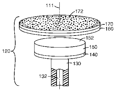
WO 2008/116049
PCT/US2008/057621
extensive refinishing can significantly increase the time, energy and cost of
removing/repairing defects such as nibs in a finish.
[0004] More generally, the same issues of blending the surface appearance
between
refinished and non-refinished areas on a surface may also arise in many other
conventional
abrading processes such as, for example, those processes involving coated
abrasive
products.
SUMMARY OF THE INVENTION
[0005] The present invention provides methods of abrading surfaces by
rotationally
reciprocating abrasive surfaces in contact with the surfaces. The present
invention may also
provide abrasive articles for use in rotationally reciprocating tools. In
addition, the present
invention may also provide methods of removing defects in a surface, where the
method
includes sanding (using a rotationally reciprocating abrasive surface)
followed by one or
more polishing operations.
[0006] As used herein, "rotational reciprocation" (and variations thereof) is
used to
describe rotation of an abrasive article about an axis of rotation in
alternating clockwise and
counter-clockwise directions. In other words, the abrasive article is first
rotated in a first
direction about an axis of rotation, stopped, rotated in an opposite
direction, stopped, etc.
[0007] Rotational reciprocation of abrasive articles may provide advantages in
the removal
of smaller defects (e.g., nibs, protrusions, etc.) from a surface as compared
to conventional
processes involving, e.g., rotating abrasive articles. Those advantages may
include, e.g.,
reduced disturbance of any orange-peel texture in the surface surrounding the
defect,
reductions in the number of steps required to complete the repair, reductions
in the total area
affected by the repair, etc.
[0008] Limiting disturbance of the orange-peel texture in the surface finish
while still
effectively removing the surface defect may, in many instances, allow removal
of such
defects without requiring treatment of the entire surface to avoid introducing
flat spots that
are unacceptable in size and/or frequency in the orange-peel texture.
2
CA 02681316 2009-09-18
WO 2008/116049
PCT/US2008/057621
[0009] Also among the potential advantages of the present invention is the
opportunity to
reduce the number of steps required to repair surface defects on, e.g., a
finished surface
(where the finish is, e.g., a clear-coat, paint, varnish, etc.). Conventional
methods of
removing such defects (sometimes referred to in the automotive industry as
"denibbing") can
require up to five steps to achieve an acceptable result. The conventional
process typically
includes: 1) sanding (to remove the protrusions); 2) scratch refinement (to
remove more
prominent sanding scratches); 3) compounding (to further remove sanding
scratches); 4)
polishing (to polish finish after steps 2 & 3); and 5) swirl elimination (to
remove swirl marks
left after polishing).
[0010] Because the pads on tools used to perform the sanding are typically
large (e.g., with
diameters in the range of 6-9 inches (15.2-22.9 centimeters)), the resulting
areas on which
steps 1-5 must be performed are also large because the size of the pads makes
it nearly
impossible to avoid affecting large areas of the surface from which defects
are being
removed. In some instances, it is as economical to refinish entire body panels
using the
steps described above. (especially where the orange-peel texture in the finish
has been
removed in large areas).
[0011] In contrast, the abrasive articles and rotationally reciprocating tools
of the present
invention may provide a user with the ability to repair surface defects in a
fraction of the
time required in the conventional 5-step process. Using the present invention,
defects may
be repaired (with limited impact on the orange-peel texture) by sanding (by
rotationally
reciprocating the abrasive articles and tools described herein) followed by
one or more
polishing operations. It may be preferred that the sanding be followed by an
initial polishing
step, followed by at least one subsequent polishing operation to remove swirl
marks left
after the initial polishing operation. In other words, the conventional five-
step process can
be performed in two or three steps.
[0012] Furthermore, because the size of the area affected during the removal
of each of the
defects is relatively small, disturbance of the orange-peel texture around the
defect is
significantly reduced as compared to defect removal (e.g., denibbing)
techniques using
conventional larger tools. As a result, the likelihood that an entire body
panel would need to
3
CA 02681316 2009-09-18
WO 2008/116049
PCT/US2008/057621
be refinished because of noticeable orange-peel flattening around each of the
defects may be
significantly reduced.
[0013] To minimize the size of the area affected during the refinishing
process, it may be
preferred to use abrasive articles with smaller abrasive surfaces as described
herein. It may,
for example, be preferred to use abrasive surfaces with a size of about 500
square
millimeters (mm2) or less, in some instances about 300 mm2 or less, or even
about 150 mm2
or less. With such small abrasive surfaces, however, conventional rotary
sanding processes
in which the abrasive surface is rotated at relatively high speeds would
typically provide
more energy than is required to remove the defect. That excessive energy also
typically
results in undesirable heat generation, deeper scratches, and/or more
aggressive removal of
material than is required ¨ particularly when removing small surface defects.
[0014] The rotating reciprocation of an abrasive article as discussed in
connection with the
present invention can, however, provide enough abrasive energy to remove the
defect. The
amount of abrasive energy is not so great, however, that the scratches and/or
material
removal are excessive. In other words, the scratches formed using a
rotationally
reciprocating tool may be shallower than those that would be formed using a
rotating
sanding tool. The shallower scratches may preferably require less extensive
refinishing as
compared to more conventional sanding/refinishing methods.
[0015] The rate at which the abrasive articles may be reciprocated can vary
based on a
variety of factors (e.g., the surface being abraded, the size of the abrasive
article, desired rate
of abrasion, etc.). It may be preferred that the reciprocating be performed at
a frequency of
at least about 60 cycles per minute (i.e., 1 Hertz) or higher (where a cycle
is a change in
direction of rotation). In some instances, it may be preferred that the
reciprocating
frequency be 2 Hz or higher, 100 Hz or higher, 500 Hz or higher, 1000 Hz or
higher, or even
2000 Hz or higher.
[0016] In one aspect, the present invention may provide a method of abrading a
surface of
a workpiece. The method includes providing an abrasive article mounted on a
shaft of a
driven tool, wherein the abrasive article has an abrasive surface with
abrasive particles
4
CA 02681316 2009-09-18
WO 2008/116049
PCT/US2008/057621
attached thereto; contacting the surface of the workpiece with the abrasive
surface of the
abrasive article; and rotationally reciprocating the abrasive surface of the
abrasive article
about an axis of rotation by rotationally reciprocating the shaft of the
driven tool, wherein
the surface of the workpiece is abraded by the abrasive particles attached to
the abrasive
surface of the abrasive article while the abrasive surface of the abrasive
article is rotationally
reciprocating about the axis of rotation.
[0017] In another aspect, the present invention may provide a conformable
abrasive article
that includes a base plate having a mounting surface; a resiliently
compressible member
attached to the mounting surface of the base plate, wherein the compressible
member has a
first major surface facing the mounting surface and a second major surface
facing away
from the mounting surface, and wherein the first major surface and the second
major surface
of the compressible member are each as large or larger than the mounting
surface of the base
plate; a flexible support layer attached to the compressible member, wherein
the support
layer has a first major surface facing the compressible member and a second
major surface
facing away from the compressible member, and wherein the first major surface
and the
second major surface of the support layer are each larger than the second
major surface of
the compressible member; and an abrasive member attached to the second major
surface of
the support layer such that an abrasive surface of the abrasive member faces
away from the
compressible member and the base plate, and wherein the abrasive surface has a
flat
abrasive surface that is coextensive with the second major surface of the
support layer.
[0018] In another aspect, the present invention may provide a abrasive tool
that includes a
powered device having an output shaft adapted to rotationally reciprocate
about an axis of
rotation; and an abrasive article with an abrasive surface that includes
abrasive particles,
wherein the abrasive article is attached the output shaft, wherein rotational
reciprocation of
the output shaft rotationally reciprocates the abrasive article about the axis
of rotation.
[0019] In another aspect, the present invention may provide a method of
repairing defects
in a workpiece surface. The method includes sanding one or more defects in a
workpiece
surface by rotationally reciprocating an abrasive surface of an abrasive
article about an axis
of rotation using the shaft of the driven tool, wherein the workpiece surface
is abraded by
CA 02681316 2009-09-18
WO 2008/116049
PCT/US2008/057621
abrasive particles attached to the abrasive surface of the abrasive article
while the abrasive
surface of the abrasive article is rotationally reciprocating about the axis
of rotation; and
polishing an area of the workpiece surface surrounding and containing each of
the one or
more defects by contacting the workpiece surface with a working surface of a
pad, wherein
the working surface of the pad is rotated in one direction about an axis of
rotation extending
through the workpiece surface and working surface of the pad, wherein an
abrasive slurry is
forced against the workpiece surface by the working surface of the pad, and
wherein the
abrasive slurry contains abrasive particles that are finer than the abrasive
particles attached
to the abrasive surface of the abrasive article.
[0020] In another aspect, the present invention may provide a method of
repairing defects
in a workpiece surface. The method includes sanding one or more defects in a
workpiece
surface by rotationally reciprocating an abrasive surface of an abrasive
article about an axis
of rotation using the shaft of the driven tool, wherein the workpiece surface
is abraded by
abrasive particles attached to the abrasive surface of the abrasive article
while the abrasive
surface of the abrasive article is rotationally reciprocating about the axis
of rotation, and
wherein rotationally reciprocating the abrasive surface comprises
reciprocating the abrasive
surface at a frequency of 1 Hz or higher. The method further includes
polishing an area of
the workpiece surface surrounding and containing each of the one or more
defects after the
sanding by contacting the workpiece surface with a working surface of a pad,
wherein the
working surface of the pad is rotated in one direction about an axis of
rotation extending
through the workpiece surface and working surface of the pad, and wherein an
abrasive
slurry is forced against the workpiece surface by the working surface of the
pad, and
wherein the abrasive slurry contains abrasive particles that are finer than
the abrasive
particles attached to the abrasive surface of the abrasive article. The method
still further
includes one or more subsequent polishing operations performed on each area
surrounding
and containing the one or more defects, wherein each of the one or more
subsequent
polishing operations comprises contacting the workpiece surface with a working
surface of
pad, wherein the working surface of the pad is rotated in one direction about
an axis of
rotation extending through the workpiece surface and working surface of the
pad, wherein
an abrasive slurry is forced against the workpiece surface by the working
surface of the pad,
6
CA 02681316 2015-08-04
60557-8062
and wherein the abrasive slurry used in each of the subsequent polishing
operations contains
abrasive particles that are finer than abrasive particles contained in the
abrasive slurry used in
a preceding polishing operation on the same area.
[0020a] According to still another aspect of the present invention,
there is provided a
method of repairing defects in a workpiece surface, the method comprising:
sanding one or
more defects in a workpiece surface by rotationally reciprocating an abrasive
surface of an
abrasive article about a first axis of rotation using a shaft of a driven
tool, wherein the
workpiece surface is abraded by first abrasive particles attached to the
abrasive surface of the
abrasive article while the abrasive surface of the abrasive article is
rotationally reciprocating
about the first axis of rotation; and free from intermediate abrasion steps
after the sanding
step, polishing an area of the workpiece surface surrounding and containing
each of the one or
more defects by contacting the workpiece surface with a working surface of a
polishing step
pad, wherein the working surface of the polishing step pad is rotated in one
direction about a
second axis of rotation extending through the workpiece surface and working
surface of the
polishing step pad, and wherein a polishing step abrasive slurry is forced
against the
workpiece surface by the working surface of the polishing step pad, and
wherein the polishing
step abrasive slurry contains second abrasive particles that are finer than
the first abrasive
particles attached to the abrasive surface of the abrasive article.
[0020b] According to yet another aspect of the present invention,
there is provided a
method of repairing defects in a workpiece surface, the method comprising:
sanding one or
more defects in a workpiece surface by rotationally reciprocating an abrasive
surface of an
abrasive article about a first axis of rotation using a shaft of a driven
tool, wherein the
workpiece surface is abraded by first abrasive particles attached to the
abrasive surface of the
abrasive article while the abrasive surface of the abrasive article is
rotationally reciprocating
about the first axis of rotation, and wherein rotationally reciprocating the
abrasive surface
comprises reciprocating the abrasive surface at a frequency of 1 Hz or higher;
free from
intermediate abrasion steps after the sanding step, polishing an area of the
workpiece surface
surrounding and containing each of the one or more defects after the sanding
by contacting the
workpiece surface with a working surface of a polishing step pad, wherein the
working
7
CA 02681316 2014-08-27
,
60557-8062
surface of the polishing step pad is rotated in one direction about a second
axis of rotation
extending through the workpiece surface and working surface of the polishing
step pad, and
wherein a polishing step abrasive slurry is forced against the workpiece
surface by the
working surface of the polishing step pad, and wherein the polishing step
abrasive slurry
contains second abrasive particles that are finer than the first abrasive
particles attached to the
abrasive surface of the abrasive article; and one or more subsequent polishing
operations
performed on each area surrounding and containing the one or more defects,
wherein each of
the one or more subsequent polishing operations comprises contacting the
workpiece surface
with a working surface of a subsequent polishing operation pad, wherein the
working surface
of the subsequent polishing operation pad is rotated in one direction about a
third axis of
rotation extending through the workpiece surface and working surface of the
subsequent
polishing operation pad, wherein a subsequent polishing operation abrasive
slurry is forced
against the workpiece surface by the working surface of the subsequent
polishing operation
pad, and wherein the subsequent polishing operation abrasive slurry used in
each of the
subsequent polishing operations contains additional abrasive particles that
are finer than the
abrasive particles contained in the abrasive slurry used in a preceding
polishing operation on
the same area.
[0021] As used herein, "resiliently compressible" (and variations
thereof) means
reducible in volume by at least 10% in response to an applied compressive
force, and further
wherein the compressed article regains at least 50% of the reduced volume
after removal of
the compressive force within one minute or less.
[0022] As used herein, a "flat abrasive surface" means that the
abrasive surface
generally defines a plane (in the absence of some deforming mechanical force
acting on the
abrasive surface) such that, when applied to a fiat workpiece surface,
rotation of the abrasive
surface typically results in some contact between the abrasive surface and the
workpiece
surface over substantially all of the area of the workpiece surface that faces
the abrasive
surface. It should be understood that a flat abrasive surface may include
structures, particles,
peaks and valleys, undulations, etc. such that not all of the workpiece
surface is in actual
contact with flat abrasive surface at all times. Further, such structures,
particles, peaks and
7a
CA 02681316 2014-08-27
,
60557-8062
valleys, undulations, etc. are not all necessarily located in the plane, but
those features will,
collectively, define a plane over the entire abrasive surface (where the
defined plane may have
a limited thickness in view of minor variations in the height of the features
defining the
plane). Examples of some flat abrasive surfaces are depicted in FIGS. 10A-
IOC.
100231 As used herein, the phrase "attached to" means attached directly to
as well as
attached to an intervening component/layer. For example, first and second
components
attached to each other may be in direct contact with each other or they may be
attached to one
or more intervening components/layers located between the first and second
components.
[0024] As used herein, the phrase "major surface" is used to refer
to surfaces that
define the thickness of an article - the phrase is typically used in
connection with films, disc-
shaped articles, etc. to refer to the flat surfaces between which the
thickness of the article is
7b
CA 02681316 2009-09-18
WO 2008/116049
PCT/US2008/057621
defined. For example, a sheet of paper includes two major surfaces and an edge
surface
extending between the two major surfaces.
[0025] This summary is not intended to describe each embodiment or every
implementation of the present invention. Rather, a more complete understanding
of the
invention will become apparent and appreciated by reference to the following
Detailed
Description of Exemplary Embodiments and claims in view of the accompanying
figures of
the drawing.
BRIEF DESCRIPTION OF THE VIEWS OF THE DRAWING
[0026] The present invention will be further described with reference to the
figures of the
drawing, wherein:
[0027] FIG. 1 is a side view of one exemplary driven tool with an attached
abrasive article.
[0028] FIG. 2 is a side view of the driven tool of FIG. 1 with the abrasive
article removed
to expose the rotationally reciprocating shaft of the driven tool.
[0029] FIG. 3 is an enlarged end view of one exemplary abrasive surface on an
exemplary
abrasive article which also illustrates one exemplary range over which an
abrasive surface
may rotationally reciprocate during use.
[0030] FIG. 4 is an exploded view of one exemplary abrasive article according
to the
present invention.
[0031] FIG. 5 is a side view of one exemplary unitary compressible article
incorporating a
compressible member and a support layer.
[0032] FIG. 6 is a side view of another exemplary unitary compressible article
incorporating a compressible member and a support layer.
[0033] FIGS. 7A & 7B depict a base plate and the base plate embedded in a
compressible
member.
8
CA 02681316 2009-09-18
WO 2008/116049
PCT/US2008/057621
[0034] FIG. 8 depicts an exemplary polishing pad and a working surface that
may be used
in connection with the defect repair methods of the invention.
[0035] FIG. 9 is a partial cross-sectional view of one exemplary polishing pad
having a
convoluted working surface.
[0036] FIGS. 10A-10C are enlarged schematic cross-sectional views of various
embodiments of abrasive layers that may be used in abrasive members of the
present
invention.
DETAILED DESCRIPTION OF EXEMPLARY EMBODIMENTS OF THE INVENTION
[0037] In the following detailed description of illustrative embodiments of
the invention,
reference is made to the accompanying figures of the drawing which form a part
hereof, and
in which are shown, by way of illustration, specific embodiments in which the
invention
may be practiced. It is to be understood that other embodiments may be
utilized and
structural changes may be made without departing from the scope of the present
invention.
[0038] FIG. 1 depicts an exemplary driven tool 10 and attached abrasive
article 20 that
may be used in connection with the present invention. FIG. 2 depicts the
driven tool 10 with
the abrasive article 20 removed, exposing a shaft 12 extending out of the
housing 14 of the
driven tool 10. In some embodiments, the shaft 12 may be partially protected
by or enclosed
within a shroud (not shown) to protect the shaft from damage if, e.g., the
tool 10 is dropped,
etc.
[0039] Although not depicted in FIGS. 1 & 2, the driven tool 10 may preferably
include a
motor, transmission (if required), power source (e.g., batteries, etc.) within
the housing 14
such that the driven tool 10 is a self-contained integral unit that need not
be connected to an
external power source, etc. In alternative embodiments, however, the driven
tool 10 may be
capable of connecting to an external power source (i.e., a power source that
is not contained
within the housing 14) to provide the energy required to move the shaft 12.
Examples of
some potentially suitable external power sources may be, e.g., pneumatic
lines, hydraulic
9
CA 02681316 2009-09-18
WO 2008/116049
PCT/US2008/057621
lines, electric power sources (e.g., external batteries, electric line voltage
(e.g., 120/220 Volt,
60 Hz), etc.).
[0040] The driven tool 10 preferably causes rotational reciprocation of the
shaft 12 about
the axis of rotation 11. Rotational reciprocation of a shaft may be provided
by a variety of
tools and mechanisms, some of which have been developed in connection with
powered
handheld toothbrushes. Examples of some potentially suitable driven tools
capable of
providing rotational reciprocation may be described in, e.g., U.S. Patent Nos.
5,054,149 (Si-
Hoe et al.); 5,311,633 (Herzog et al.); 5,822, 821 (Sham); etc. Although the
abrasive
surfaces used in connection with the invention may preferably be oriented
perpendicular to
the axis about which the shaft 12 of the tool 10 rotates, the abrasive
surfaces may
alternatively have any selected orientation relative to the axis 11 about
which shaft 12
rotates. Examples of mechanisms capable of reciprocally rotating a pad that is
not
perpendicular to the axis 11 may be found in, e.g., U.S. Patent Nos. 5,054,149
(Si-Hoe et
al.); 5,311,633 (Herzog et al.); 5,822, 821 (Sham); etc. and those mechanisms
may be used
in connection with the present invention.
[0041] The rotational reciprocation of the shaft 12 preferably causes
corresponding
rotational reciprocation of the abrasive article 20 attached or coupled to the
shaft 12. FIG. 3
is an enlarged end view of the abrasive article 20 with axis of rotation 11
depicted as exiting
from the page (preferably, as shown, located at the center of the abrasive
article). The
rotational reciprocation causes the abrasive article 20 to rotate about the
axis of rotation in a
manner that results in alternating clockwise and counter-clockwise rotation
about the axis of
rotation 11.
[0042] It may be preferred that the rotation in any one direction be limited
to a selected
range or arc. One example of such an arc is depicted in FIG. 3 as encompassing
an angle a
(alpha) extending between points A and B at the periphery of the abrasive
article 20. In
some embodiments, the arc over which the abrasive article 20 rotationally
reciprocates may
be less than 360 degrees, 180 degrees or less, or even 90 degrees or less. The
arc may be
fixed for any particular driven tool 10 such that the shaft 12 rotationally
reciprocates over a
given angular arc. Alternatively, the reciprocation arc length may be
adjustable.
CA 02681316 2009-09-18
WO 2008/116049
PCT/US2008/057621
[0043] The reciprocating movement may have a frequency of at least about 60
cycles per
minute or higher (i.e., 1 Hertz (Hz) or higher) (where a cycle is a change in
direction of
rotation). In some embodiments, the reciprocating frequency may be 2 Hz or
higher, 100 Hz
or higher, 500 Hz or higher, 1000 Hz or higher, or even 2000 Hz or higher. In
some
instances, the arc and the frequency of the reciprocations may be related,
e.g., larger arcs
may result in reduced frequencies, smaller arcs may result in higher
frequencies, etc. The
reciprocation frequency for any particular driven tool 10 may be fixed,
although in some
instance the user may be able to adjust the reciprocation frequency provided
by the driven
tool 10 (using, e.g., a variable speed motor, etc.).
[0044] Although the abrasive articles according to the present invention are
depicted
herein as having abrasive surfaces in the form of circular articles, the
abrasive articles may
be manufactured in any other suitable shape, although shapes approximating
circles (e.g.,
hexagons, octagons, decagons, etc.) may be preferred.
[0045] Abrasive articles according to the present invention are useful for
abrading
(including finishing) a workpiece where the workpiece can be manufactured from
any of a
variety of types of material such as painted substrates (e.g., having a clear
coat, base (color)
coat, primer or e-primer), coated substrates (e.g., with polyurethane,
lacquer, etc.), plastics
(thermoplastic, thermosetting), reinforced plastics, metal, (carbon steel,
brass, copper, mild
steel, stainless steel, titanium and the like) metal alloys, ceramics, glass,
wood, wood-like
materials, composites, stones (including gem stones), stone-like materials,
and combinations
thereof. The workpiece may be flat or may have a shape or contour associated
with it.
Examples of common workpieces that may be abraded by the abrasive articles and
methods
of the invention include metal or wooden furniture, painted or unpainted motor
vehicle
surfaces (car doors, hoods, trunks, etc.), plastic automotive components
(headlamp covers,
tail-lamp covers, other lamp covers, arm rests, instrument panels, bumpers,
etc.), flooring
(vinyl, stone, wood and wood-like materials), counter tops, and other plastic
components.
[0046] During abrading processes it may be desirable to provide a liquid to
the surface of
the workpiece and/or the abrasive surface. The liquid may include water and/or
an organic
11
CA 02681316 2009-09-18
WO 2008/116049
PCT/US2008/057621
compound, and additives such as defoamers, degreasers, liquids, soaps,
corrosion inhibitors,
and the like.
[0047] As depicted in FIGS. 1 & 2, it may be preferred that the abrasive
article 20 be
removably coupled to the shaft 12 such that the abrasive article 20 can be
replaced after use.
FIG. 4 is an enlarged perspective view of one abrasive article 120 that may be
used in
connection with a driven tool in the present invention.
[0048] Although the depicted abrasive article 120 includes a variety of
components as
discussed herein, one common component is a flat abrasive surface 172 arranged
for use in
connection with a driven tool as discussed herein. The flat abrasive surface
172 may
preferably be oriented normal (i.e., orthogonal, perpendicular, etc.) to an
axis of rotation 111
about which the abrasive surface is preferably rotationally reciprocated
during use. In an
abrasive article constructed of components with two opposing flat surfaces
that are oriented
parallel to each other (as depicted in FIG. 4), all of the major surfaces of
the components
will typically also be oriented normal to the axis of rotation 111. It should
be noted that
these surfaces are preferably flat in the absence of deformation by an
external force acting
on the abrasive article 120.
[0049] The depicted abrasive article 120 includes an optional sleeve coupling
130 that
supports a rigid base plate 140. The sleeve coupling 130 and the rigid base
plate 140 may
preferably be formed as a unitary molded article, although in some embodiments
the
coupling 130 may be separate from the base plate 140 with the two components
attached by
any suitable attachment technique.
[0050] Also depicted in connection with the abrasive article 120 is an
optional resiliently
compressible member 150 attached to the mounting surface of the base plate
140. Although
it is hidden by the compressible member 150 in FIG. 4, it will be understood
that the
mounting surface of the base plate 140 is the major surface of the base plate
140 that faces
away from a shaft located in the coupling 130 and, correspondingly, that faces
one of the
major surfaces of the compressible member 150.
12
CA 02681316 2009-09-18
WO 2008/116049
PCT/US2008/057621
[0051] The abrasive article 120 of FIG. 4 also includes an optional flexible
support layer
160 attached to the compressible member 150 (although in the exploded view of
FIG. 4 the
support layer 160 is detached from the compressible member 150). An abrasive
member
170 with an abrasive surface 172 is attached to the major surface of the
support layer 160
such that the abrasive surface 172 faces away from the compressible member
150.
[0052] The sleeve coupling 130 as depicted in FIG. 4 may preferably include a
bore 132 in
which the shaft of a driven tool (not shown) is retained such that movement of
the shaft is
transferred to the coupling 130 and the base plate 140 attached thereto. The
bore 132 may,
for example, have a shape complementary to the shaft of the driven tool such
that the
rotational reciprocating motion is transferred from the shaft to the sleeve
coupling 130.
[0053] Although one example of a connection between the shaft of a driven tool
and the
abrasive article 120 is depicted in connection with FIGS. 1, 2, & 4, it should
be understood
that any connection technique/apparatus capable of transferring the rotational
reciprocating
motion could be used in place of that depicted. Examples of alternative
attachments may
include, e.g., friction fit components, threaded couplings, clamps, etc.
[0054] Although replacement of the entire abrasive article 120 may be
preferred in some
embodiments of the invention, in other embodiments, the base plate 140 may be
fixedly
attached to the shaft of the driven tool with replacement of the abrasive
surface 172 being
accomplished by replacement of other components in the system. For example,
the
compressible member 150 may be removably secured to the base plate 140, in
which case
replacement of the abrasive surface 172 would be accompanied by replacement of
the
support layer 160 and the compressible member 150. In still another
alternative, the
compressible member 150 may be fixedly attached to the base plate 140, such
that
replacement of the abrasive surface 172 is accomplished by removing the
support layer 160
from the compressible member 150. In such an embodiment, the compressible
member 150
would remain attached to the base plate 140. In yet another alternative,
replacement of the
abrasive surface 172 may be accomplished by removing the abrasive member 170
itself
from the support layer 160.
13
CA 02681316 2014-08-27
60557-8062
[0055] A number of different techniques may be used to removably secure the
different
components in the abrasive article 120 to each other to provide the different
options for
replacement of the abrasive surface 172 discussed above. Examples of some
potentially
suitable attachment systems may include, e.g., adhesives, mechanical fastening
systems
(e.g., hook and loop fasteners, etc.), etc. Examples of some potentially
suitable attachment
systems may be described in, e.g., U.S. Patent Nos. 3,562,968 (Johnson et
al.); 3,667,170
(Mackay, Jr.); 3,270,467; 3,562,968 (Block et al.); 5,672,186 (Chelsey etal.);
and 7,121,924
(Fritz et al.); and U.S. Patent Application Publication No. 2003/0143938
(Braunschweig et al.).
[0056] It is preferred that a majority (if not all) of the abrasive surface
172 of the abrasive
article 120 be maintained in contact with the surface of a workpiece to be
abraded even if
the axis of rotation 111 about which the abrasive surface 172 is rotationally
reciprocating is
canted relative to (i.e., is not normal to) the workpiece surface. The
interaction of the
various components provided in the abrasive articles of the present invention
preferably
provides an abrasive article 120 in which one or more of the components can
compress or
deform such that the contact between the abrasive surface 172 and the
workpiece surface is
facilitated even if the axis of rotation is somewhat canted.
[0057] With respect to the abrasive article 120, a significant portion of any
such
deformation may preferably occur in the compressible member 150. In some
embodiments,
however, additional deformation may also occur in one or more other components
of the
abrasive article 120. For example, the base plate 140 may exhibit some
flexibility in
response to applied forces during use of the abrasive article 120 (although in
some
embodiments, the base plate 140 may preferably be rigid ¨ i.e., the base plate
140 may
preferably exhibit no significant deformation to the forces encountered in
routine use).
[0058] The support layer 160 may also/alternatively exhibit compressibility in
response to
forces applied on the abrasive surface 172. As discussed below, the support
layer 160 may,
for example, be constructed of a compressible foam material. Although
compressibility may
be optional, the support layer 160 is preferably resiliently flexible such
that it can bend and
elastically deform in response to forces encountered during use of the
abrasive article.
14
CA 02681316 2009-09-18
WO 2008/116049
PCT/US2008/057621
[0059] The support layer 160 provides some support to the abrasive member 170
outside
of the area occupied by the compressible member 150, but preferably allows
more deflection
of the abrasive surface 172 than the compressible layer 150. In other words,
it is preferred
that the support offered to the abrasive member 170 by the underlying
components to which
it is attached is lower at the perimeter of the abrasive member 170 than in
the center of the
abrasive member 170.
[0060] In the depicted embodiment, the major surface of the compressible
member 150
that faces the mounting surface of the base plate 140 is preferably as large
or larger than the
mounting surface of the base plate 140. Similarly, the major surface 152 of
the
compressible member 150 that faces away from the base plate 140 is also
preferably as large
or larger than the mounting surface of the base plate 140. By providing a
compressible
member 150 that is at least as large as the mounting surface of the base plate
140, adverse
effects from the concentration of forces at the perimeter of the base plate
140 (e.g.,
excessive gouging, scratching, etc.) may be reduced or eliminated because of
the
deformation in the compressible member 150.
[0061] In a similar manner, the addition of a support layer 160 that is also
compressible
may serve to further reduce or eliminate adverse effects that might otherwise
occur at the
perimeter of the compressible member 150. It should, however, be understood
that
compressibility of the support layer 160 may be optional in those embodiments
in which the
compressible member 150 has characteristics that mitigate the need for
additional
compressibility in the support layer 160. In some embodiments of the
invention, the support
layer 160 may itself be optional where, e.g., the abrasive member 170 is
capable of
providing sufficient support outside of the area occupied by the support layer
160.
[0062] Because the support layer 160 is provided to offer additional support
to the
abrasive member 170 outside of the major surfaces of the compressible member
150, it is
typically preferred that the major surfaces of the support layer 160 (i.e.,
the surfaces facing
towards and away from the compressible member 150) be larger than the major
surface 152
of the compressible member 150. It may be preferred that the major surface 152
of the
compressible member 150 occupy less than 75% (or even less than 50%) of the
major
CA 02681316 2009-09-18
WO 2008/116049
PCT/US2008/057621
surface of the support layer 160 that faces the compressible member 150 (or
the major
surface of the abrasive member 170 facing the compressible member 150 if no
support layer
160 is present).
[0063] It may further be preferred that the major surfaces of the support
layer 160 be as
large as the major surface of the abrasive member 170 attached to the support
layer 160 (i.e.,
the facing major surfaces of the support layer 160 and the abrasive member 170
may
preferably be coextensive with each other). Alternatively, the major surface
of the support
layer 160 may occupy at least 90% of the major surface of the abrasive member
170 that
faces the support layer.
[0064] Although the base plate 140, compressible member 150, support layer
160, and
abrasive member 170 are separate and discrete articles in the abrasive article
120, in some
embodiments one or more of these components may alternatively be combined into
unitary
articles. For example, it may be possible to construct a single unitary
article that provides
compressible support in the central portion of the abrasive surface 172 and
reduced support
when moving away from the central portion of the abrasive surface 172 such
that, e.g., the
compressible member 150 and the support layer 160 can be replaced by a single
unitary
article. In another example, it may be possible to combine the functions of
the support layer
160 and abrasive member 170 into a unitary article.
[0065] FIGS. 5-7 depict alternative embodiments in which one or more of the
components
are combined into unitary articles. FIG. 5 is a side view of a unitary
compressible support
article 280 in which the compressible member and support layer are combined.
The unitary
compressible support article 280 may preferably include a compressible member
portion 250
and integrated support layer portion 260. It may be preferred that the support
layer portion
260 form an annular ring 262 surrounding the compressible member 250. At least
the
annular ring 262 of the support layer 260 may preferably be thinner than the
compressible
member portion 250 such that the annular ring 262 of the support layer portion
provides less
support outside of the compressible member portion 250.
16
CA 02681316 2009-09-18
WO 2008/116049
PCT/US2008/057621
[0066] An abrasive member (not shown) may preferably be attached to the
surface 282 of
the compressible support article 280 (although in some instances, an abrasive
layer may be
formed directly on the surface 282 as is discussed herein). The compressible
support article
280 may be formed as a single, homogenous mass of material (e.g., a single
type of foam,
etc.) or it may include different materials that are combined into a unitary
article (e.g., insert
molded, etc.).
[0067] FIG. 6 depicts another embodiment of a unitary compressible support
article 380 in
which the transition between the support member portion 350 and the support
layer portion
360 is more gradual than that depicted in connection with the compressible
support article
280 of FIG. 5.
[0068] FIGS. 7A & 7B depict yet another variation in which a base plate 440 is
located
within the compressible member 450. In FIG. 7A, the base plate 440 is depicted
separately,
while FIG. 7B depicts the base plate 440 embedded in the compressible member
450. The
compressible member 450 and embedded base plate 440 may be manufactured by any
suitable process, e.g., insert molding, etc. In an embodiment such as that
depicted in FIGS.
7A & 7B, only the portion of the compressible member 450 located on the side
of the
mounting surface 442 of the base plate 440 will act to support an abrasive
surface. As such,
although a portion of the compressible member 450 is attached to the back side
of the base
plate 440, the working portion of the compressible member 450 remains attached
to the
mounting surface 442 of the base plate 440 and preferably operates as
described herein.
[0069] Furthermore, although the base plate 440 is depicted as being embedded
in a
compressible member 450, it should be understood that the base plate may
alternatively be
embedded in a unitary compressible support article, examples of which are
depicted and
described in connection with FIGS. 5 & 6 herein.
[0070] In addition to providing abrasive methods that involve rotational
reciprocation
along with abrasive articles, tools and kits for practicing the methods, the
present invention
also provides methods of repairing defects from a finished workpiece surface
where the
finished workpiece surface has a clear-coat, paint, varnish, etc. finish in
which defects such
17
CA 02681316 2009-09-18
WO 2008/116049
PCT/US2008/057621
as nibs, etc. are found. As discussed herein, it may be preferred that the
defects be removed
from the surface by abrading (sanding) the defect and the immediate area
surrounding the
defect with limited disturbance of any orange-peel (or other) texture found on
the workpiece
surface.
[0071] The sanding operation performed as a part of the repair methods of the
invention
preferably involves sanding one or more defects from a workpiece surface by
rotationally
reciprocating an abrasive surface of an abrasive article about an axis of
rotation using the
shaft of a driven tool as described herein. The workpiece surface is abraded
by abrasive
particles attached to the abrasive surface of the abrasive article while the
abrasive surface of
the abrasive article is rotationally reciprocating about the axis of rotation
as described
herein.
[0072] After the sanding of a defect is complete, the repair may further
involve a polishing
operation in which an area of the workpiece surface containing and surrounding
the defect is
worked to remove and/or reduce scratches formed during the sanding operation.
As
depicted in FIG. 8, the polishing operation may preferably be performed by
contacting the
workpiece surface 90 with the working surface 92 of a pad 94 while rotating
the pad 94
about an axis of rotation 96 that extends through the workpiece surface 90 and
working
surface 92 of the pad 94. The pad 94 is rotated about at least one axis 96 in
only one
direction (in contrast to the rotational reciprocating motion used in
connection with the
abrasive surface).
[0073] It may be preferred that the pad 94 be attached to a dual action rotary
tool such that
the pad 94 moves in what is commonly referred to as a random orbital pattern.
During
operation of dual action rotary tool, the pad moves along a circular path
disposed
concentrically of or to orbit relative to a first axis about which the pad 94
is rotating, while
the pad 94 is also free to rotate about a second axis that is typically
parallel to but offset
from the first axis. Examples of some potentially suitable dual action rotary
tools may be
described in, e.g., U.S. Patent Nos. 2,794,303 and 4,854,085. Some potentially
suitable dual
action rotary tools are described in the examples described in connection with
this invention.
An exemplary dual action rotary tool both spins and oscillates. In some
embodiments the
18
CA 02681316 2009-09-18
WO 2008/116049
PCT/US2008/057621
dual action rotary tool has a throw of 3/8 inch (9.525mm), in further
embodiments the tool
has a throw of 12 mm, and in yet a further embodiment the tool has a throw of
14mm.
[0074] The rotating pad 94 may or may not be moved across the workpiece
surface 90 (in
addition to the rotation about axis 96) as desired. The rotating pad 94 may
preferably be
forced against the workpiece surface 90 such that the working surface 92 of
the pad 94
conforms to the shape of the workpiece surface 90.
[0075] The polishing also preferably includes the use of an abrasive slurry 98
located
between the working surface 92 of the pad 94 and the workpiece surface 90
while rotating
the working surface of the pad against the workpiece surface. The abrasive
slurry 98 may be
applied to the working surface of the pad, to the workpiece surface, or both
the working
surface of the pad and the workpiece surface. The abrasive slurry preferably
contains
abrasive particles in a liquid or paste-like carrier. The abrasive particles
in the abrasive
slurry are preferably finer than the abrasive particles used in the abrasive
surface of the
abrasive member used to perform the sanding operation. Such abrasive slurries
are
commonly used in surface finishing and may be described as rubbing compound,
polishing
compound, glazing compound, etc.
[0076] In a polishing operation of the present invention, a variety of
materials may
potentially be used for the working surfaces of the pads. Some potentially
suitable materials
for forming the working surfaces of the pads may include natural fibers,
synthetic fibers,
combinations thereof, and foams (see, e.g., U.S. Patent Nos. 3,418,675;
4,962,562;
5,396,737; and 5,846,123). The pads may have working surfaces that are flat or
that are
convoluted (including projecting portions 191 and recessed portions 193 on a
pad 190 as
depicted in, e.g., FIG. 9). Examples of some potentially suitable convoluted
pads with
projecting and recessed portions may be described in, e.g., U.S. Patent No.
5,396,737 and
others.
[0077] The pads used for polishing in the methods of the present invention
also preferably
include resiliently compressible materials to assist with conformance of the
working surface
to the workpiece surface. The working surface itself may be constructed of
resiliently
19
CA 02681316 2009-09-18
WO 2008/116049
PCT/US2008/057621
compressible material and/or materials supporting the working surface may be
resiliently
compressible. Examples of some potentially suitable pads for use in the
polishing methods
of the invention may be identified in the Examples provided at the end of this
document
(before the claims).
[0078] Because the sanding operation may preferably be performed using smaller
abrasive
articles as described herein, the polishing operations may also be performed
using pads with
working surfaces that are also relatively small. For example, it may be
preferred that the
working surfaces of the pads have an area of about 2000 mm2 or less, in some
instances
about 1000 mm2 or less, and in some instances about 500 mm2 or less.
[0079] While the rotational reciprocating motion of an abrasive article (even
a smaller
abrasive article as discussed herein) can provide enough abrasive energy to
remove defects,
the amount of abrasive energy is preferably small enough that the scratches
formed are
shallower and/or less material is removed from the workpiece surface (as
compared to a
process using a rotating sanding tool). The shallower scratches may preferably
require less
extensive refinishing as compared to more conventional sanding/refinishing
methods.
[0080] In the surface repair methods of the present invention, the sanding of
any area
surrounding and containing one of the defects may preferably be followed by
one or more
subsequent polishing operations on the same area. If two or more polishing
operations are
performed after the sanding, it may be preferred that any abrasive particles
used in the
successive polishing operations be successively finer. In other words, it may
be preferred
that the abrasive particles in any subsequent polishing operation be finer
than the abrasive
particles in the abrasive slurry used in the preceding polishing operation.
[0081] In another variation, the working surfaces of the pads used in methods
that include
two or more polishing operations may be the same, i.e., the working surfaces
may have the
same shape and be manufactured of the same materials. Alternatively, the
working surfaces
of the pads used in two or more polishing operations may be different in one
or more
respects, i.e., the shape and/or materials used for the working surfaces may
be different
between the two polishing operations.
CA 02681316 2009-09-18
WO 2008/116049
PCT/US2008/057621
[0082] The following discussions provide additional descriptions of the
various
components that may be present in the abrasive articles used in connection
with the present
invention.
[0083] BASE PLATES:
[0084] The base plate used in connection with the present invention preferably
supplies a
platform on which the remainder of the abrasive article is supported. It may
be preferred
that the base plate also include a structure that can couple with the shaft of
a driven tool as
discussed herein, although that coupling structure can be provided separate
from the base
plate.
[0085] The base plate preferably provides a rigid platform that does not
significantly
deform or deflect in response to the forces exerted on the base plate during
normal use. It
may be preferred that the base plate provide a flat mounting surface onto
which the
compressible member may be attached. The flat mounting surface may preferably
be
normal to the axis of rotation about which the base plate (and, thus, the
abrasive article)
reciprocates during use.
[0086] Examples of some potentially suitable materials from which the base
plate may be
manufactured can include, e.g., woods, metals, plastics, composites, etc.
[0087] COMPRESSIBLE MEMBERS:
[0088] The optional compressible members used in connection with the present
invention
preferably support a central portion of the abrasive surface of the abrasive
articles used in
connection with the present invention. It is theorized that the resilient
compressibility of the
compressible member limits the concentration of forces applied by the abrasive
surface at
the edges of the base plate. It may also be preferred that in addition to
resilient
compressibility, the compressible member may also provide some torsional flex
to the
system, such that the compressible member may twist in response to changes in
the
rotational direction of the driven shaft of the tool.
21
CA 02681316 2009-09-18
WO 2008/116049
PCT/US2008/057621
[0089] The compressible member is preferably attached to a mounting surface of
the base
plate by any suitable technique or combination of techniques (e.g., hot melt
adhesives,
pressure sensitive adhesives, curable adhesives, glues, heat laminating,
chemical welding,
insert molding, etc.). Useful adhesives may include, for example, acrylic
pressure sensitive
adhesive, rubber-based pressure sensitive adhesives, waterborne lattices,
solvent-based
adhesives, and two-part resins (e.g., epoxies, polyesters, or polyurethanes).
Examples of
potentially suitable pressure sensitive adhesives may include those derived
from acrylate
polymers (for example, polybutyl acrylate) polyacrylate esters), acrylate
copolymers (for
example, isooctyl acrylate/ acrylic acid), vinyl ethers (for example,
polyvinyl n-butyl ether);
alkyd adhesives; rubber adhesives (for example, natural rubbers, synthetic
rubbers and
chlorinated rubbers); and mixtures thereof. An example of one pressure
sensitive adhesive
coating is described in U.S. Pat. No. 5,520,957 (Bange et al.). These
adhesives may also be
used to attach various other components (e.g., support layer, abrasive member,
etc.) in the
abrasive article as well.
[0090] The material used to form the compressible member may include gas
(e.g., air),
liquid (e.g., water, oil), foam (e.g., as described herein), semi-solid gel or
paste,
combinations thereof, etc. In some instances, the compressible member may be
in the form
of a torsion spring. The compressible members may be manufactured as unitary
articles
(e.g., a single uniform layer of foam) or they may include one or more
materials (e.g., a gel
encased in an elastomeric bladder). It may be preferred , however, that the
major surface of
the compressible member that faces the abrasive member in the construction is
flat (i.e.,
does not have the shape of a dome, curve, cone, truncated cone, ridges,
polyhedron,
truncated polyhedron, or other non-planar shapes (e.g., yurt-shaped surfaces).
[0091] In some embodiments, the compressible material may include an
elastomer. For
example, the compressible material may comprise, or even consist essentially
of, at least one
elastomeric gel or foamed elastomeric gel, typically comprising a highly
plasticized
elastomer. Examples of potentially useful elastomeric gels may include
polyurethane
elastomer gels, e.g., as described in U.S. Pat. No. 6,908,979 (Arendoski);
SEEPS elastomer
gels, e.g., as described in U.S. Pat. No. 5,994,450 and 6,797,765 (both to
Pearce); styrene-
22
CA 02681316 2009-09-18
WO 2008/116049
PCT/US2008/057621
butadiene-styrene/oil gels; and silicone elastomer gels, e.g., as described in
U.S. Pat. No.
6,013,711 (Lewis et al.)
[0092] For solid and gel materials, the elastic modulus (measured at 1 Hz and
25 C) for
the compressible material may preferably be between about 1500 and about 4.9 x
105
Pascals (Pa), for example, between about 1750 and about 1 x 10⁵ Pa, although
this is not a
requirement. Examples of such compressible materials may include styrene-
butadiene-
styrene/oil gels (e.g., having an elastic modulus of 1992 Pa at 1 Hz and 25
C), urethane
foam (e.g., having an elastic modulus of 3.02 x 10⁵ Pa at 1 Hz and 25 C or
4.31 x 10⁵ Pa at
1 Hz and 25 C); and elastomeric urethane rubber (e.g., having modulus 4.89 x
105 Pa at 1
Hz and 25 C).
[0093] Typically, the thickness of the compressible member will be selected
based on
factors such as, for example, the intended use and the overall size of the
abrasive article.
Further, it may be preferred that the thickness of the compressible member be
substantially
uniform over its major surfaces. In some embodiments, the thickness of the
compressible
member may be, e.g., about 0.5 millimeters (mm) or more, in some instances 1
mm or more,
or even 1.5 mm or more. At the upper end, the thickness of the compressible
members may
preferably be about 5 mm or less, preferably about 3 mm or less, or even about
2 mm or
less. Compressible members with thicknesses outside of these ranges may also
be used.
[0094] SUPPORT LAYER:
[0095] As discussed herein, the optional support layer is preferably a
flexible, resilient
layer that provides support to the abrasive member during use. The support
layer may
preferably be located between the compressible member and the abrasive member
in the
abrasive articles of the present invention. The support layer may be attached
to the
compressible member by any suitable technique or combination of techniques
(e.g., hot melt
adhesives, pressure sensitive adhesives, curable adhesives, glues, heat
laminating, chemical
welding, coextrusion, insert molding, etc.).
23
CA 02681316 2009-09-18
WO 2008/116049
PCT/US2008/057621
[0096] In addition to being flexible and resilient, it may be preferred that
the support layer
also be compressible such that it may compress in response to the forces
exerted on the
abrasive surface supported by the support layer during use.
[0097] In some embodiments the support layer may preferably be constructed of
resilient
compressible material, e.g., foams, etc. Some potentially useful compressible
foams may
include, for example, polyvinyl chloride foams, chloroprene rubber foams,
ethylene/propylene rubber foams, butyl rubber foams, polybutadiene foams,
polyisoprene
foams, EPDM polymer foams, polyurethane foams, ethylene-vinyl acetate foams,
neoprene
foams, and styrene/butadiene copolymer foams.
[0098] The thickness of the support layer may be, e.g., about 0.01 mm or more,
or even
0.1 mm or more. At the upper end, the support layer may have a thickness of
about 2 mm or
less, or even 1 mm or less. Support layers with thicknesses outside of these
ranges may also
be used.
[0099] ABRASIVE MEMBERS:
[0100] The abrasive members used in the abrasive articles of the present
invention provide
the abrasive surface used to abrade workpieces. The abrasive members may
preferably
include an abrasive layer that is optionally affixed to a flexible backing
(i.e., a coated
abrasive article). The optional flexible backing of the abrasive member may be
elastic or
inelastic.
[0101] In some embodiments, it may be possible to use the support layer as a
flexible
backing for the abrasive member. In such embodiments, the abrasive layer may
preferably
be attached to the support layer as a part of the manufacturing process for
the abrasive
member. In other embodiments, the abrasive member is manufactured separately
and then
attached to the optional support layer.
[0102] The abrasive member may be attached to the support layer (or
compressible
member if no support layer is present) by any suitable technique or
combination of
24
CA 02681316 2009-09-18
WO 2008/116049
PCT/US2008/057621
techniques (e.g., hot melt adhesives, pressure sensitive adhesives, curable
adhesives, glues,
heat laminating, chemical welding, coextrusion, etc.).
[0103] In some embodiments, the abrasive layers may include make and size
layers and
abrasive particles as shown, for example, in FIG. 10A where abrasive layer 570
includes
make layer 574, abrasive particles 576, size layer 578, and optional supersize
580.
Potentially useful make, size, and optional supersize layers, flexible coated
abrasive articles,
and methods of making the same may include, for example, those described in
U.S. Patent
Nos. 4,588,419 (Caul et al.); 4,734,104 (Broberg); 4,737,163 (Larkey);
4,751,138 (Tumey
et al.); 5,078,753 (Broberg et al.); 5,203,884 (Buchanan et al.); 5,152,917
(Pieper et al.);
5,378,251 (Culler et al.); 5,366,523 (Rowenhorst et al.); 5,417,726 (Stout et
al.); 5,436,063
(Follett et al.); 5,490,878 (Peterson et al.); 5,496,386 (Broberg et al.);
5,609,706 (Benedict et
al.); 5,520,711 (Helmin); 5,954,844 (Law et al.); 5,961,674 (Gagliardi et
al.); 4,751,138
(Tumey et al.); 5,766,277 (DeVoe et al.); 6,059,850 (Lise et al.); 6,077,601
(DeVoe et al.);
6,228,133 (Thurber et al.); and 5,975,988 (Christianson); those marketed by 3M
Company
under the trade designations "260L IMPERIAL FINISHING FILM"; etc.
CA 02681316 2009-09-18
WO 2008/116049
PCT/US2008/057621
[0104] In other embodiments, the abrasive layer may include abrasive particles
in a binder,
typically substantially uniformly distributed throughout the binder, as shown,
for example,
in FIG. 10B where abrasive layer 670 includes binder 674 and abrasive
particles 676.
Details concerning materials and methods for making such potentially suitable
abrasive
layers may be found, for example, in U.S. Pat. Nos. 4,927,431 (Buchanan et
al.); 5,014,468
(Ravipati et al.); 5,378,251 (Culler et al.); 5,942,015 (Culler et al.);
6,261,682 (Law); and
6,277,160 (Stubbs et al.); and U.S. Pat. Appin. Publ. Nos. 2003/0207659 Al
(Annen et al.)
and 2005/0020190 Al (Schutz et al.); etc.
[0105] As discussed herein, in those embodiments where the abrasive member
itself does
not include a separate backing layer, it may be possible to apply a slurry of
abrasive particles
in a binder precursor directly to the support layer material described herein,
and then at least
partially cure the slurry to form the abrasive member on the support layer.
Examples of
potentially useful flexible coated abrasive articles of this embodiment may
include those
described in U.S. Pat. No. 6,929,539 (Schutz et al.).
[0106] In some embodiments, the abrasive layer may be in the form of a
structured
abrasive layer, for example, as depicted in FIG. 10C where structured abrasive
layer 770
includes abrasive composites 775 (where the term "abrasive composite" refers
to a body that
includes abrasive particles and a binder). The abrasive composites 775 include
abrasive
particles 776 dispersed throughout binder 774. In those embodiments where the
abrasive
member itself does not include a separate backing layer, it may be possible to
form the
structured abrasive layer 770 directly on the support layer material as
described herein.
[0107] Structured abrasive layers that may be used in connection with the
present
invention may include abrasive composites in the form of a plurality of non-
randomly
shaped bodies. The abrasive composites 775 may preferably be arranged
according to a
predetermined pattern (e.g., as an array).
[0108] In some embodiments, at least a portion of the abrasive composites 775
may
preferably be "precisely shaped" abrasive composites. This means that the
shape of the
abrasive composites is defined by relatively smooth surfaced sides that are
bounded and
26
CA 02681316 2009-09-18
WO 2008/116049
PCT/US2008/057621
joined by well-defined edges having distinct edge lengths with distinct
endpoints defined by
the intersections of the various sides. The terms "bounded" and "boundary"
refer to the
exposed surfaces and edges of each composite that delimit and define the
actual three-
dimensional shape of each abrasive composite. These boundaries are readily
visible and
discernible when a cross-section of an abrasive article is viewed under a
scanning electron
microscope. These boundaries separate and distinguish one precisely shaped
abrasive
composite from another even if the composites abut each other along a common
border at
their bases. By comparison, in an abrasive composite that does not have a
precise shape, the
boundaries and edges are not well defined (e.g., where the abrasive composite
sags before
completion of its curing). Typically, precisely shaped abrasive composites are
arranged on
the backing according to a predetermined pattern or array, although this is
not a requirement.
[0109] Shaped abrasive composites may be arranged such that some of their work
surfaces
are recessed from the outermost surfaces of the abrasive layer.
[0110] Suitable optional flexible backings that may be used in connection with
abrasive
members may include flexible backings used in the abrasive art such as, for
example,
flexible polymeric films (including primed polymeric films and elastomeric
polymeric
films), elastomeric cloth, polymeric foam (e.g., polyvinyl chloride foam,
polyurethane foam,
etc.), and combinations thereof. Examples of suitable flexible polymeric films
include
polyester films, polypropylene films, polyethylene films, ionomer films (e.g.,
those available
under the trade designation "SURLYN" from E. I. du Pont de Nemours & Co.,
Wilmington,
Delaware), vinyl films, polycarbonate films, and laminates thereof.
[0111] Structured abrasive composites may be prepared by forming a slurry of
abrasive
particles and a solidifiable or polymerizable precursor of the abovementioned
binder resin
(i.e., a binder precursor), contacting the slurry with a backing member (or
directly with the
support layer), and solidifying and/or polymerizing the binder precursor
(e.g., by exposure
to electromagnetic radiation or thermal energy) in a manner such that the
resulting structured
abrasive article has a plurality of shaped abrasive composites affixed to the
backing
member.
27
CA 02681316 2009-09-18
WO 2008/116049
PCT/US2008/057621
[0112] Examples of some potentially suitable energy sources may include, e.g.,
thermal
energy and radiant energy (including electron beam, ultraviolet light, and
visible light).
[0113] In some embodiments the slurry may be coated directly onto a production
tool
having precisely shaped cavities therein and brought into contact with the
backing, or coated
on the backing and brought to contact with the production tool. In such an
embodiment, the
slurry is typically then solidified or cured while it is present in the
cavities of the production
tool. U.S. Pat. No. 6,929,539 (Schutz et al.) discloses some potentially
suitable procedures
to accomplish this process.
[0114] Precisely-shaped abrasive composites may be of any three-dimensional
shape that
results in at least one of a raised feature or recess on the exposed surface
of the abrasive
layer. Useful shapes may include, for example, cubic, prismatic, pyramidal
(e.g., square
pyramidal or hexagonal pyramidal), truncated pyramidal, conical, frusto-
conical, pup-tent
shaped, ridge shaped, etc. Combinations of differently shaped and/or sized
abrasive
composites may also be used in the same abrasive member. The abrasive layer of
the
structured abrasive member may be continuous or discontinuous.
[0115] For fine finishing applications, the density of shaped abrasive
composites on the
abrasive surface may typically be in a range of from at least about 1,000,
about 10,000, or
even at least about 20,000 abrasive composites per square inch (e.g., at least
about 150,
about 1,500, or even about 7,800 abrasive composites per square centimeter) up
to and
including about 50,000, about 70,000, or even as many as about 100,000
abrasive
composites per square inch (up to and including about 7,800, about 11,000, or
even as many
as about 15,000 abrasive composites per square centimeter), although greater
or lesser
densities of abrasive composites may also be used.
[0116] Further details concerning structured abrasive layers having precisely
shaped
abrasive composites, and methods for their manufacture may be found, for
example, in U.S.
Pat. Nos. 5,152,917 (Pieper et al.); 5,304,223 (Pieper et al.); 5,435,816
(Spurgeon et al.);
5,672,097 (Hoopman); 5,681,217 (Hoopman et al.); 5,454,844 (Hibbard et al.);
5,549,962
(Holmes et al.); 5,700,302 (Stoetzel et al.); 5,851,247 (Stoetzel et al.);
5,910,471
28
CA 02681316 2009-09-18
WO 2008/116049
PCT/US2008/057621
(Christianson et al.); 5,913,716 (Mucci et al.); 5,958,794 (Bruxvoort et al.);
6,139,594
(Kincaid et al.); 6,923,840 (Schutz et al.); and U.S. Pat. Appin. Nos.
2003/0022604 (Annen
et al.).
[0117] Some structured abrasive members having precisely shaped abrasive
composites
that may be useful for practicing the present invention are commercially
available as films
and/or discs, for example, as marketed under the trade designation "3M TRIZACT
FINESSE-IT" by 3M Company, Saint Paul, Minnesota. Examples include "3M FINESSE-
IT TRIZACT FILM, 466LA" available in grades A7, AS and A3. Structured abrasive
members having larger abrasive composite sizes may also be useful for
practicing the
present invention, for example, those marketed under the trade designation
"TRIZACT CF",
available from 3M Company.
[0118] Structured abrasive members may also be prepared by coating a slurry
comprising
a polymerizable binder precursor, abrasive particles, and an optional silane
coupling agent
through a screen that is in contact with a backing. In this embodiment, the
slurry is typically
then further polymerized (e.g., by exposure to an energy source) while it is
present in the
openings of the screen thereby forming a plurality of shaped abrasive
composites generally
corresponding in shape to the screen openings. Further details concerning this
type of
screen coated structured abrasive may be found, for example, in U.S. Pat. Nos.
4,927,431
(Buchanan et al.); 5,378,251 (Culler et al.); 5,942,015 (Culler et al.);
6,261,682 (Law); and
6,277,160 (Stubbs et al.).
[0119] In some embodiments, a slurry comprising a polymerizable binder
precursor,
abrasive particles, and an optional silane coupling agent may be deposited on
a backing in a
patterned manner (e.g., by screen or gravure printing), partially polymerized
to render at
least the surface of the coated slurry plastic but non-flowing, a pattern
embossed upon the
partially polymerized slurry formulation, and subsequently further polymerized
(e.g., by
exposure to an energy source) to form a plurality of shaped abrasive
composites affixed to
the backing. Embossed structured abrasive members prepared by this and related
methods
are described, for example, in U.S. Patent Application Publication No.
2001/0041511 (Lack
et al.). Commercially available examples of such embossed structured abrasive
members
29
CA 02681316 2009-09-18
WO 2008/116049
PCT/US2008/057621
are believed to include abrasive belts and discs available from Norton-St.
Gobain Abrasives
Company, Worcester, Massachusetts, under the trade designation "NORAX" such as
for
example, "NORAX U264 ¨ X80", "NORAX U266 ¨ X30", "NORAX U264 ¨ X80",
"NORAX U264 ¨ X45", "NORAX U254 ¨ X45, X30", "NORAX U264 ¨ X16", "NORAX
U336 ¨ XS" and "NORAX U254 ¨ AF06".
[0120] Structured abrasive layers may also be prepared by coating a slurry
comprising a
polymerizable binder precursor, abrasive particles, and an optional silane
coupling agent
through a screen that is in contact with the elastic member, which may
optionally have a tie
layer or surface treatment thereon. In this embodiment, the slurry is
typically then further
polymerized (e.g., by exposure to an energy source such as heat or
electromagnetic
radiation) while it is present in the openings of the screen thereby forming a
plurality of
shaped abrasive composites generally corresponding in shape to the screen
openings.
Further details concerning this type of screen coated structured abrasive may
be found, for
example, in U.S. Pat. Nos. 4,927,431 (Buchanan et al.); 5,378,251 (Culler et
al.); 5,942,015
(Culler et al.); 6,261,682 (Law); and 6,277,160 (Stubbs et al.); and in U.S.
Publ. Pat. Appl.
No. 2001/0041511 (Lack et al.).
[0121] Useful polymerizable binder precursors that may be cured to form the
above-
mentioned binders are well-known and include, for example, thermally curable
resins and
radiation curable resins, which may be cured, for example, thermally and/or by
exposure to
radiation energy. Exemplary polymerizable binder precursors include phenolic
resins,
aminoplast resins, urea-formaldehyde resins, melamine-formaldehyde resins,
urethane
resins, polyacrylates (e. g., an aminoplast resin having pendant free-
radically polymerizable
unsaturated groups, urethane acrylates, acrylate isocyanurate, (poly)acrylate
monomers, and
acrylic resins), alkyd resins, epoxy resins (including bis-maleimide and
fluorene-modified
epoxy resins), isocyanurate resins, allyl resins, furan resins, cyanate
esters, polyimides, and
mixtures thereof. Polymerizable binder precursors may contain one or more
reactive
diluents (e.g., low viscosity monoacrylates) and/or adhesion promoting
monomers (e.g.,
acrylic acid or methacrylic acid).
CA 02681316 2009-09-18
WO 2008/116049
PCT/US2008/057621
[0122] If either ultraviolet radiation or visible radiation is to be used, the
polymerizable
binder precursor typically further comprise a photoinitiator. Examples of
photoinitiators
that generate a free radical source include, but are not limited to, organic
peroxides, azo
compounds, quinones, benzophenones, nitroso compounds, acyl halides,
hydrazones,
mercapto compounds, pyrylium compounds, triacrylimidazoles, bisimidazoles,
phosphene
oxides, chloroalkyltriazines, benzoin ethers, benzil ketals, thioxanthones,
acetophenone
derivatives, and combinations thereof.
[0123] Cationic photoinitiators generate an acid source to initiate the
polymerization of an
epoxy resin. Cationic photoinitiators can include a salt having an onium
cation and a
halogen containing a complex anion of a metal or metalloid. Other cationic
photoinitiators
include a salt having an organometallic complex cation and a halogen
containing complex
anion of a metal or metalloid. These are further described in U.S. Pat. No.
4,751,138.
Another example of a cationic photoinitiator is an organometallic salt and an
onium salt
described in U.S. Pat. No. 4,985,340; European Patent Publication Nos. EP
306,161 and EP
306,162. Still other cationic photoinitiators include an ionic salt of an
organometallic
complex in which the metal is selected from the elements of Periodic Groups
IVB, VB, VIB,
VIIB and VIIIB.
[0124] The polymerizable binder precursor may also include resins that are
curable by
sources of energy other than radiation energy, such as condensation curable
resins.
Examples of such condensation curable resins include phenolic resins, melamine-
formaldehyde resins, and urea-formaldehyde resins.
[0125] The binder precursor and binder may include one or more optional
additives
selected from the group consisting of grinding aids, fillers, wetting agents,
chemical blowing
agents, surfactants, pigments, coupling agents, dyes, initiators, energy
receptors, and
mixtures thereof. The optional additives may also be selected from the group
consisting of
potassium fluoroborate, lithium stearate, glass bubbles, inflatable bubbles,
glass beads,
cryolite, polyurethane particles, polysiloxane gum, polymeric particles, solid
waxes, liquid
waxes and mixtures thereof.
31
CA 02681316 2009-09-18
WO 2008/116049
PCT/US2008/057621
[0126] Abrasive particles useful in the present invention can generally be
divided into two
classes: natural abrasives and manufactured abrasives. Examples of useful
natural abrasives
include: diamond, corundum, emery, garnet (off-red color), buhrstone, chert,
quartz, garnet,
emery, sandstone, chalcedony, flint, quartzite, silica, feldspar, natural
crushed aluminum
oxide, pumice and talc. Examples of manufactured abrasives include: boron
carbide, cubic
boron nitride, fused alumina, ceramic aluminum oxide, heat treated aluminum
oxide (both
brown and dark grey), fused alumina zirconia, glass, glass ceramics, silicon
carbide, iron
oxides, tantalum carbide, chromia, cerium oxide, tin oxide, titanium carbide,
titanium
diboride, synthetic diamond, manganese dioxide, zirconium oxide, sol gel
alumina-based
ceramics, silicon nitride, and agglomerates thereof. Examples of sol gel
abrasive particles
can be found in U.S. Pat. Nos. 4,314,827 (Leitheiser et al.); 4,623,364
(Cottringer et al);
4,744,802 (Schwabel); 4,770,671 (Monroe et al.) and 4,881,951 (Wood et al.).
[0127] The size of an abrasive particle is typically specified to be the
longest dimension of
the abrasive particle. In most cases there will be a range distribution of
particle sizes. The
particle size distribution may be tightly controlled such that the resulting
abrasive article
provides a consistent surface finish on the workpiece being abraded, however,
broad and/or
polymodal particle size distributions may also be used.
[0128] The abrasive particle may also have a shape associated with it.
Examples of such
shapes include rods, triangles, pyramids, cones, solid spheres, hollow spheres
and the like.
Alternatively, the abrasive particle may be randomly shaped.
[0129] Abrasive particles can be coated with materials to provide the
particles with
desired characteristics. For example, materials applied to the surface of an
abrasive particle
have been shown to improve the adhesion between the abrasive particle and the
polymer.
Additionally, a material applied to the surface of an abrasive particle may
improve the
adhesion of the abrasive particles in the softened particulate curable binder
material.
Alternatively, surface coatings can alter and improve the cutting
characteristics of the
resulting abrasive particle. Such surface coatings are described, for example,
in U.S. Pat.
Nos. 5,011,508 (Wald et al.); 3,041,156 (Rowse et al.); 5,009,675 (Kunz et
al.); 4,997,461
32
CA 02681316 2009-09-18
WO 2008/116049
PCT/US2008/057621
(Markhoff-Matheny et al.); 5,213,591 (Celikkaya et al.); 5,085,671 (Martin et
al.) and
5,042,991 (Kunz et al.).
[0130] In some embodiments, for example, those including shaped abrasive
composites,
the abrasive particles used in the abrasive members of the present invention
may preferably
have a particle size of about 0.1 micrometer (gm) or more. At the upper end of
the range,
the abrasive particles may have a particle size of about 450 gm or less, or
even 100 gm or
less. In some embodiments, the abrasive particles may have a size within a
range of from
JIS grade 800 (14 gm at 50% midpoint) or higher, or even JIS grade 1000 (12 gm
at 50%
midpoint). At the opposite end of the range, the abrasive particles have a
size of JIS grade
6000 (2 gm at 50% midpoint) or lower, in some instances JIS grade 4000 (3 gm
at 50%
midpoint) or lower, or even JIS grade 2000 (5-8 gm at 50% midpoint) or lower.
[0131] Typically, the abrasive particles used in the present invention have a
Moh's
hardness of at least 8, more typically above 9; however, abrasive particles
having a Moh's
hardness of less than 8 may be used.
[0132] Aspects of this invention may be further illustrated by the following
non-limiting
examples, but the particular materials and amounts thereof recited in these
examples, as well
as other conditions and, details, should not be construed to unduly limit this
invention.
[0133] SANDING EXAMPLES
[0134] The following descriptions demonstrate exemplary use of the abrasive
articles,
tools and methods of the present invention and comparative abrasive articles,
tools and
methods.
[0135] ROTATIONALLY RECIPROCATING TOOL: The rotationally-reciprocating
driven tool used in Examples 1-4 was manufactured as follows. The plastic
shell from the
brushhead of a battery-powered toothbrush, Model "Oral B AdvancePower 450TX"
(Braun
GmbH, Kronberg, Germany) was removed. The exposed brushhead connector was cut
to a
length of approximately 1 inch (2.54 cm), and the end sanded to form a smooth
distal face
perpendicular to the length of the drive shaft of the toothbrush. A 0.25 inch
(0.64 cm)
33
CA 02681316 2009-09-18
WO 2008/116049
PCT/US2008/057621
diameter, 0.033 inch (0.84 mm) thick hard plastic disc was then cemented to
the distal face
using a 2-part epoxy resin and hardener (commercially available under the
trade designation
"Quick Weld Compound" from Dynatex, Elizabethtown, Kentucky) to form a
removable
base plate assembly with a 0.25 inch diameter mounting surface oriented
perpendicular to
the rotationally reciprocating shaft of the tool. The tool was powered by two
3-volt AA-
sized lithium batteries, "Part # U-3191" obtained from Apex Battery, Anaheim
Hills,
California.
[0136] CONVENTIONAL ROTARY TOOL: The conventional sanding tool used in the
examples was a pneumatically driven dual action sander, Model Number 57500
(Dynabrade,
Inc., Clarence, New York) in combination with a 1.25-inch (3.2 cm) back-up pad
(commercially available under the trade designation FINESSE-IT ROLOC Sanding
Pad,
Part No. 02345 from 3M, St. Paul, Minnesota) to support the abrasive discs
attached to the
conventional sanding tool as discussed in connection with the comparative
examples.
[0137] STRUCTURED ABRASIVE MEMBERS: Structured abrasive members used in
connection with the examples and sanding tests described herein were
manufactured using
the following materials (identified below by the abbreviations appearing at
the beginning of
each of the following descriptions):
[0138] AS1: trimethylolpropane triacrylate monomer having a molecular weight
of 296
and functionality of 3, available under the trade designation "SR 351" from
Sartomer
Company, Exton, Pennsylvania;
[0139] A52: 2 ¨ phenoxyethyl acrylate aromatic monomer having a molecular
weight of
192 and functionality of 1 available under the trade designation "SR 339" from
Sartomer
Company;
[0140] A53: a polymeric disperant available under the trade designation
"Solplus D520"
from Noveon, Inc., Cleveland, Ohio;
[0141[A54: gamma-methacryloxypropyltrimethoxy silane resin modifier available
under the
trade designation "Silquest A174" from Witco Corporation, Greenwich,
Connecticut;
34
CA 02681316 2009-09-18
WO 2008/116049
PCT/US2008/057621
[0142] AS5: ethyl 2, 4, 6-trimethylbenzoylphenylphosphinate photoinitiator
available
under the trade designation "Lucirin TPO-L" from BASF Corp., Charlotte, North
Carolina;
and
[0143] AS6: green silicon carbide abrasive particles having a JIS grade size
of 1500 and
an average particle size of 8.0 micrometers (jam) at 50% point, available
under the trade
designation "Fujimi GC 1500" from Fujimi Abrasives Company, Elmhurst, IL.
[0144] An abrasive slurry was made at 20 degrees Centigrade ( C) by mixing the
listed
components in parts by weight until homogeneous: 12.9 parts of AS1, 19.5 parts
of AS2, 3.1
parts of AS3, 1.9 parts of AS4, 1.1 parts of ASS and 61.5 parts of AS6. The
slurry was
applied by knife coating to a polypropylene abrasive production tool made
according to the
methods described in U.S. Patent No. 6,846,232 (Braunschweig et al.). The
dimensions of
the abrasive production tool used in Examples 1-4 below are described in
Example 2 of U.S.
Patent No. 6,846,232.
[0145] The coated production tool was applied to the primed face of 0.003 inch
(76
micrometer (jam)) polyester film available under the trade designation
SCOTCHPAK
polyester film from 3M Company, St. Paul, Minnesota. The production tool was
then
irradiated with an ultraviolet (UV) lamp, type "D" bulb, from Fusion Systems
Inc.,
Gaithersburg, Maryland, at 600 Watts per inch (236 Watts per centimeter
(W/cm)) while
moving the web at 30 feet per minute (9.14 meters/minute), at a nip pressure
of 90 pounds
per square inch (620.5 kilopascals (kPa)) for a 10 inch (25.4 cm) wide web,
and mandrel
temperature of 60 C. The web with the structured abrasive layer formed
thereon was
separated from the production tool and die-cut into 0.5 inch (1.27 cm)
diameter disc-
structured abrasive members.
[0146] EXAMPLE 1: An abrasive article was manufactured using transfer adhesive
(commercially available under the trade designation "9453LE" from 3M Company)
that was
applied to the non-abrasive face of a 0.5 inch (1.27 cm) diameter structured
abrasive
member (manufactured as described above). The larger 0.5 inch diameter
abrasive member
was centered over and attached to the smaller 0.25 inch diameter mounting
surface of the
CA 02681316 2009-09-18
WO 2008/116049
PCT/US2008/057621
base plate assembly. The abrasive article of Example 1 thus included the
following
components depicted in FIG. 4: the base plate 140 and abrasive member 170
attached
directly to the base plate 140. The abrasive article was then used as
described in Sanding
Test No. 1 below.
[0147] EXAMPLE 2: An abrasive article was manufactured by die-cutting a 0.5
inch
(1.27 cm) diameter polyvinyl foam disc, 0.027 inch (0.69 mm) thick from an
adhesive
bandage commercially available under the trade designation NEXCARE ADHESIVE
STRIP BANDAGE from 3M Company. The adhesive liner was removed and the adhesive
face of the foam disc was attached to the non-abrasive major surface of a 0.5
inch diameter
structured abrasive member (manufactured as described above). The transfer
adhesive of
Example 1 was then applied to the non-adhesive face of the foam disc. The
transfer
adhesive-coated major surface of the larger 0.5 inch diameter polyvinyl foam
disc (with its
attached structured abrasive member) was then centered over and attached to
the smaller
0.25 inch diameter mounting surface of the base plate assembly. The abrasive
article of
Example 2 thus included the following components depicted in FIG. 4: the base
plate 140,
support layer 160 (polyvinyl foam disc), and abrasive member 170. The support
layer 160
was attached directly to the base plate 140. The abrasive article was then
used as described
in Sanding Test No. 1 below.
[0148] EXAMPLE 3: An abrasive article was made according to the method
described in
Example 2, except that the 0.5 inch (1.27 cm) diameter polyvinyl foam was
replaced by a
5/16 inch (7.9 mm), 0.090 inch (2.29 mm) thick disc of polyurethane foam,
commercially
available under the trade designation "R600U-090" from Illbruck Company,
Minneapolis,
Minnesota. The larger 0.5 inch diameter structured abrasive member was
centered over the
smaller 5/16 inch diameter polyurethane foam disc. The 5/16 inch diameter
polyurethane
foam disc was centered on the 0.25 inch diameter mounting surface of the base
plate
assembly. The abrasive article of Example 3 thus included the following
components
depicted in FIG. 4: the base plate 140, compressible member 150 (polyurethane
foam disc),
and abrasive member 170. The abrasive member 170 was attached directly to the
36
CA 02681316 2009-09-18
WO 2008/116049
PCT/US2008/057621
compressible member 150. The abrasive article was then used as described in
Sanding Test
No. 1 below.
[0149] EXAMPLE 4: An abrasive article was manufactured that included all of
the
components depicted in FIG. 4, i.e., the base plate 140 (as described in
connection with the
rotationally reciprocating tool above), the compressible member 150 (the
polyurethane foam
disc described in connection with Example 3), the support layer 160 (the
polyvinyl foam
disc described in connection with Example 2), and the abrasive member 170 (a
structured
abrasive member as described above). Except for the adhesive already located
on one side
of the polyvinyl foam disc, the transfer adhesive identified in Example 1 was
used to attach
the components to each other. The smaller diameter components (the base plate
140 and
polyurethane foam compressible member 150) were centered on each and the
larger
components (the polyvinyl foam support layer 160 and the structured abrasive
member 170)
were centered on the compressible member. The abrasive article was then used
as described
in Sanding Test No. 1 below.
[0150] COMPARATIVE EXAMPLE A: An abrasive article in the form of a 1.25-inch
(3.2 cm) diameter, grade JIS 3000, abrasive disc (commercially available under
the trade
designation "466LA AS, Part No. 56251" from 3M Company) was mounted on the
conventional sanding tool described above. The abrasive article was then used
as described
in Sanding Test No. 2 below.
[0151] COMPARATIVE EXAMPLE B: An abrasive article was formed using an
abrasive sheet commercially available under the trade designation "401Q
WETORDRY
Grade 2000" from 3M Company that was folded to a suitable shape for use in the
manual
Sanding Test No. 3 below.
[0152] TEST MEASUREMENTS: A clear-coated, black-painted, cold rolled steel
test
panel having an orange-peel texture, 18 by 24 inches (45.7 cm by 61 cm), part
number
"APR45077" was obtained from ACT Laboratories, Inc., Hillsdale, Michigan.
[0153] ORANGE PEEL: The level of "orange peel" finish on the test panel was
measured using a surface texture analyzer, model "WaveScan DOI", obtained from
BYK-
37
CA 02681316 2009-09-18
WO 2008/116049
PCT/US2008/057621
Gardner USA, Columbia, Maryland. Wavescan values reported below represent an
average
of 3 scans, each 5 cm in length, of different areas of the sanded test area,
measured after
polishing. It is theorized that departure from the control (non-sanded) panel
values, in
particular W, and Wd, reflect changes in orange peel due to the sanding
process.
[0154] SURFACE FINISH: The surface finish (Rz - the maximum vertical distance
between the highest and lowest point of a test area) was measured after the
sanding step
using a profilometer, model "SURTRONIC 3+ PROFILOMETER" obtained Taylor
Hobson,
Inc., Leicester, England. The Rz values, reported below represent the average
of 5
individual measurements of a 2 centimeter by 6 centimeter sanded area.
[0155] GOUGING: Gouging was a subjective assessment of the level of macro
surface
irregularities caused by excessive canting (i.e., off-angle, non-planar, etc.)
during the
sanding process. Gouging values are reported on a subjective scale of zero (0)
to five (5),
where zero (0) represents no irregularities.
[0156] SANDING TEST NO. 1: The abrasive articles of Examples 1-4 were used on
the
rotationally reciprocating tool to sand an area of the test panel. For each
different abrasive
article the tool was switched on and, with minimal lateral movement and a
sanding angle of
zero degrees (i.e., the flat abrasive surface was held parallel to the
workpiece surface), a
previously identified defect in the form of a protrusion in the test panel was
sanded until
removed to establish a baseline sanding time of 7 seconds. The abrasive
article on the tool
was replaced and a fresh area of the test panel sanded for the same amount of
time. The
abrasive article was replaced and an adjacent area was then sanded for 7
seconds. This
process was repeated until the matte or sanded area on the test panel was 2 cm
by 6 cm, after
which the area was outlined using a permanent marker for subsequent
identification after
polishing.
[0157] Each sanded area was then polished for 6 seconds at 1400 rpm using the
following
configuration: Polisher: Dewalt electric buffer, model number "DW849" obtained
from
Dewalt Industrial Tool Corp., Hampstead, Maryland; Backup Pad: "Perfect-it
Backup Pad
38
CA 02681316 2009-09-18
WO 2008/116049
PCT/US2008/057621
#05718"; Polishing Pad: "Perfect-it Foam Polishing Pad #05725"; and Finisher:
"Perfect-it
3000 Trizact Spot Finishing Material #06070", all available from 3M Company.
[0158] COMPARATIVE SANDING TEST NO. 2: The abrasive member of
Comparative Example A was attached to the backup pad of conventional sanding
tool
described and the pneumatic line pressure attached to the tool was set at 90
pounds per
square inch (psi) (620.5 kiloPascals (kPa)). With minimal lateral movement and
a sanding
angle of zero degrees, a previously identified protrusion in the test panel
was sanded until
removed, thereby establishing a baseline sanding time of 3 seconds. The
abrasive disc was
replaced with another sample and an adjacent area was then sanded for 3
seconds. This
process was repeated once more until the matte area was approximately 3 cm by
9 cm, after
which the area was outlined using a permanent marker. Each sanded area was
then polished
according to the method described in Sanding Test No. 1.
[0159] SANDING TEST NO. 3: By applying light finger pressure, and with minimal
lateral movement, the test panel was manually sanded using unidirectional
strokes for 3
seconds with the abrasive article described in Comparative Example B. The
abrasive article
was replaced and an adjacent area sanded. This was repeated until the sanded
area was
approximately 2 by 6 cm.
[0160] Table 1 presents the results of the sanding tests discussed above:
[0161] Table 1
Abrasive Sample Sanding Gouging Wa Wb Wc Wd We Rz
Test (lam)
Control Panel N/A N/A 4.7 16.5 13.4 16.7
12.5 N/A
Example 1 1 5 11.7 24.7 21.3 28.2 19.9 0.81
Example 2 1 3 3.3 8.1 7.1 17.4 12.8 0.71
Example 3 1 2 4.0 9.0 6.4 16.1 20.6 0.33
39
CA 02681316 2009-09-18
WO 2008/116049
PCT/US2008/057621
Example 4 1 0 5.4 17.6 10.3 13.8 10.3
0.33
Comparative A 2 0 5.7 10.3 2.9 5.0 11.9 0.48
Comparative B 3 3 4.4 24.3 24.9 24.5
13.3 1.47
N/A = Not applicable
[0162] DEFECT REPAIR EXAMPLES
[0163] The following descriptions demonstrate exemplary methods of defect
removal and
polishing using the abrasive articles, tools and methods of the present
invention as well as a
comparative conventional method.
[0164] TEST PANEL: A steel automobile hood with a black painted finish was
prepared
by spray painting a clear-coat over the black painted finish. The clear-coat
finish was
commercially available under the trade designation AUTOCLEAR III from Akzo
Noble,
Narcross, Georgia, and curing for 40 minutes at 140 F (60 C).
[0165] COMPARATIVE EXAMPLE C: The following conventional five-step repair
process was performed on the twelve (12) defects on a test panel. The test
panel was
cleaned between steps by wiping off residual abrasive slurry using a detail
cloth (obtained
under the trade designation PERFECT-IT detail cloth, Part No. 06020 from 3M
Company.
A fresh detailing cloth was used for the final polishing step.
[0166] Step 1 (Defect Removal): An abrasive article formed as described in
Comparative Example B was used by applying light finger pressure, and with
minimal
lateral movement, to remove twelve (12) paint defects (nibs) in the surface of
the test panel
described above. Sanding time to remove all of the defects was 3 minutes.
[0167] Step 2 (Scratch Refinement): A 6-inch (15.2 cm) diameter backup pad,
commercially available under the trade designation HOOKIT II disk pad (Part
Number
05251 from 3M Company) was attached to a dual action sander, Model Number
21035
(Dynabrade, Inc., Clarence, New York). A 6-inch (15.2 cm) diameter interface
pad, trade
designation HOOKIT II SOFT interface pad (Part Number 05274 from 3M Company)
was
CA 02681316 2009-09-18
WO 2008/116049
PCT/US2008/057621
attached to the backup pad. A 6-inch (15.2 cm) diameter foam pad, trade
designation
TRIZACT HOOKIT II foam disc (Part Number 02075, Grade P-3000, also from 3M
Company) was then attached to the interface pad. The scratches formed during
the defect
removal of Step 1 were refined by applying pressure to the areas containing
the scratches
using the foam pad while operating the dual action sander at a line pressure
set at 60 pounds
per square inch (psi) (413.7 kiloPascals (kPa)) with the pad held generally
parallel to the
surface of the test panel. Scratch refinement time to refine the scratches in
each of the
sanded areas was 3 minutes 30 seconds.
[0168] Step 3 (Compounding): An 8-inch (20.3 cm) backup pad, commercially
available
under the trade designation PERFECT-IT backup pad (Part Number 05718 from 3M
Company), was attached to an 8-inch (20.3 cm) buffing tool, Model Number DW
849 from
Dewalt Industrial Tool Corporation, Hampstead, Maryland. A 9-inch (22.9 cm)
wool pad,
commercially available under the trade designation PERFECT-IT III compounding
pad (Part
Number 05719 from 3M Company) was attached to the backup pad. An abrasive
slurry
commonly referred to as rubbing compound (commercially available as PERFECT-IT
3000
EXTRA CUT rubbing compound from 3M Company) was applied to the sanded and
refined
areas of the test panel and buffed for 8 minutes using the wool pad while
operating the
buffing tool at 1,800 revolutions per minute (rpm).
[0169] Step 4 (Polishing): Step 3 was repeated except that the wool pad was
replaced by
an 8-inch (20.3 cm) foam polishing pad (commercially available under the trade
designation
PERFECT-IT foam polishing pad, Part Number 05725 from 3M Company) and the
abrasive
slurry (rubbing compound) used in Step 3 was replaced with a second abrasive
slurry
including finer abrasive particles (PERFECT-IT 3000 swirl mark remover, Part
Number
06064 also from 3M Company). The polishing step was performed for a total of
six (6)
minutes.
[0170] Step 5 (Swirl Elimination): Step 4 was repeated except that the swirl
mark remover
of Step 4 was replaced with a third abrasive slurry including still finer
abrasive particles
(commercially available as PERFECT-IT 3000 ULTRAFINA SE polish, Part Number
06068, available from 3M Company). The foam polishing pad used in Step 4 was
also
41
CA 02681316 2009-09-18
WO 2008/116049
PCT/US2008/057621
replaced with a different foam polishing pad (commercially available as
PERFECT-IT
ULTRAFINA foam polishing pad, Part Number 05733, from 3M Company). The swirl
elimination step was performed for a total of four (4) minutes.
[0171] EXAMPLE 5: Twelve (12) defects in the clear-coated surface of a test
panel were
repaired using exemplary abrasive articles and methods of the invention in a
three (3) step
process as described herein. The test panel was cleaned between steps as
described in
connection with Comparative Example C.
[0172] Step 1 (Defect Removal): An abrasive article as described in Example 4
was used
on the rotationally reciprocating tool described above. For each defect to be
removed, the
tool was used to sand the defect with minimal lateral movement and a sanding
angle of zero
degrees (i.e., the abrasive surface was held parallel to the surface of the
test panel). The tool
and abrasive article were used to remove twelve (12) defects (paint nibs) in
the test panel
surface. Sanding time to remove the twelve defects was 2.5 minutes.
[0173] Step 2 (Compounding): A 1-inch (2.54 cm) adapter (commercially
available under
the trade designation ROLOC holder, Part Number 07500 from 3M Company) was
attached
to an 18-volt cordless drill, Model Number BTD140 from Makita Corp., La
Mirada,
California. A 1.25-inch (3.2 cm) diameter backup pad (commercially available
under the
trade designation FINESSE-IT ROLOC disc pad, Type J, Part Number 67415 from 3M
Company) was attached to the adaptor. A 1.25-inch (3.2 cm) foam pad (die cut
from a
larger PERFECT-IT foam polishing pad, Part Number 05725 from 3M Company) was
attached to the backup pad. An abrasive slurry (commercially available as
PERFECT-IT
3000 swirl mark remover, Part Number 06064 also from 3M Company) was applied
to the
sanded areas and buffed at approximately 1,500 rpm using the polishing pad.
The
compounding step was performed for a total of three (3) minutes.
[0174] Step 3 (Swirl Elimination): The polishing pad used in Step 2 was
replaced with 1-
inch diameter (2.54 cm) buffing pad (die-cut from a larger pad PERFECT-IT
ULTRAFINA
foam polishing pad, Part Number 05733 from 3M Company) and the abrasive slurry
used in
Step 2 was replaced with a second abrasive slurry containing finer abrasive
particles
42
CA 02681316 2009-09-18
WO 2008/116049
PCT/US2008/057621
(commercially available as PERFECT-IT 3000 ULTRAFINA SE polish, Part Number
06068, available from 3M Company). The swirl elimination step was performed by
rotating
the buffing pad at 1800 rpm for a total of 3 minutes.
[0175] EXAMPLE 6: Twelve (12) defects in the clear-coated surface of a test
panel were
repaired using exemplary abrasive articles and methods of the invention in a
three (3) step
process as described herein. The test panel was cleaned between steps as
described in
connection with Comparative Example C.
[0176] Step 1 (Defect Removal): Step 1 of Example 5 was performed as described
in
Example 5, except that the defect removal step was performed for a total of 2
minutes 20
seconds.
[0177] Step 2 (Compounding): Step 2 of Example 5 was performed as described in
Example 5, except that the compounding step was performed for a total of 3
minutes 10
seconds.
[0178] Step 3 (Swirl Elimination): Step 5 of Comparative Example C was
performed for a
total of 2 minutes and 20 seconds.
[0179] EXAMPLE 7: Twelve (12) defects in the clear-coated surface of a test
panel were
repaired using exemplary abrasive articles and methods of the invention in a
three (3) step
process as described herein. The test panel was cleaned between steps as
described in
connection with Comparative Example C.
[0180] Step 1 (Defect Removal): Step 1 of Example 5 was performed as described
in
Example 5, except that the defect removal step was performed for a total of 2
minutes 30
seconds.
[0181] Step 2 (Compounding): Step 2 of Example 5 was performed as described in
Example 5, except that the drill was replaced by a dual action sander (Model
Number 57502
from Dynabrade Company) operated at a line pressure set at 90 psi (620 kPa).
The
compounding step was performed for a total of 3 minutes 15 seconds.
43
CA 02681316 2009-09-18
WO 2008/116049
PCT/US2008/057621
[0182] Step 3 (Swirl Elimination): Step 5 of Comparative Example C was
performed,
except that the dual action sander of Step 2 in this example was used in place
of the buffing
tool used in Step 5 of Comparative Example C. The dual action sander was
operated at a
line pressure set at 90 psi (620 kPa). In addition, a 1 inch (2.54 cm) foam
polishing pad was
die cut from a larger polishing pad (commercially available as PERFECT-IT
ULTRAFINA
foam polishing pad, Part Number 05733, from 3M Company). The swirl elimination
step
was performed for a total of three (3) minutes
[0183] EXAMPLE 8: Twelve (12) defects in the clear-coated surface of a test
panel were
repaired using exemplary abrasive articles and methods of the invention in a
three (3) step
process as described herein. The test panel was cleaned between steps as
described in
connection with Comparative Example C.
[0184] Step 1 (Defect Removal): Step 1 as described in Example 5 was repeated
except
that the time taken was 2 minutes 30 seconds.
[0185] Step 2 (Compounding): Step 2 as described in Example 7 was repeated,
except
that the time taken was 3 minutes 5 seconds.
[0186] Step 3 (Swirl Elimination): Step 3 as described in Example 6 was
repeated, except
that the time taken was 2 minutes 10 seconds.
[0187] EXAMPLE 9: Twelve (12) defects in the clear-coated surface of a test
panel were
repaired using exemplary abrasive articles and methods of the invention in a
three (3) step
process as described herein. The test panel was cleaned between steps as
described in
connection with Comparative Example C.
[0188] Step 1 (Defect Removal): An abrasive article as described in Example 4
was used
on the rotationally reciprocating tool described above. For each defect to be
removed, the
tool was used to sand the defect with minimal lateral movement and a sanding
angle of
zero degrees (i.e., the abrasive surface was held parallel to the surface of
the test panel).
The tool and abrasive article were used to remove twelve (12) defects (paint
nibs) in the
test panel surface. Sanding time to remove the twelve defects was 2.5 minutes.
44
CA 02681316 2009-09-18
WO 2008/116049
PCT/US2008/057621
[0189] Step 2 (Compounding): A 3-inch (7.62 cm) Dynabuffer Model 57126
Commercially
available from Dynabrade Company. Equipped with a 3 inch (7.62 cm) backup pad
Hookit
II part number 05270 Commercially available from 3M company. A 3 inch ( 7.62
cm)
Perfect-it Hookit II buffing pad part number 05721 commercially available from
3M
Company. An abrasive slurry (commercially available as PERFECT-IT 3000 swirl
mark
remover, Part Number 06064 also from 3M Company) was applied to the sanded
areas and
buffed at approximately 5,000 rpm using the polishing pad. The compounding
step was
performed for a total of two (2) minutes.
[0190] Step 3 (Swirl Elimination): The polishing pad used in Step 2 was
replaced with 3-
inch diameter (7.62 cm) buffing pad (die-cut from a larger pad PERFECT-IT
ULTRAFINA
foam polishing pad, Part Number 05733 from 3M Company) and the abrasive slurry
used in
Step 2 was replaced with a second abrasive slurry containing finer abrasive
particles
(commercially available as PERFECT-IT 3000 ULTRAFINA SE polish, Part Number
06068, available from 3M Company). The swirl elimination step was performed A
3-inch
(7.62 cm) Dynabuffer Model 57126 Commercially available from Dynabrade Company
approximately 5,000 rpm for a total of 2 minutes 30 Sec.
[0191] EXAMPLE 10: Twelve (12) defects in the clear-coated surface of a test
panel were
repaired using exemplary abrasive articles and methods of the invention in a
three (3) step
process as described herein. The test panel was cleaned between steps as
described in
connection with Comparative Example C.
[0192] Step 1 (Defect Removal): An abrasive article as described in Example 4
was used on
the rotationally reciprocating tool described above. For each defect to be
removed, the tool
was used to sand the defect with minimal lateral movement and a sanding angle
of zero
degrees (i.e., the abrasive surface was held parallel to the surface of the
test panel). The tool
and abrasive article were used to remove twelve (12) defects (paint nibs) in
the test panel
surface. Sanding time to remove the twelve defects was 2.5 minutes.
CA 02681316 2009-09-18
WO 2008/116049 PCT/US2008/057621
[0193] Step 2 (Compounding): A 3-inch (7.62 cm) Dynabuffer Model 57126
Commercially
available from Dynabrade Company. Equipped with a 3 inch (7.62 cm) backup pad
Hookit
II part number 05270 Commercially available from 3M Company. A 3 inch ( 7.62
cm)
Perfect-it Hookit II buffing pad part number 05721 commercially available from
3M
Company. An abrasive slurry (commercially available as PERFECT IT 3000 swirl
mark
remover, Part Number 06064 also from 3M Company) was applied to the sanded
areas and
buffed at approximately 5,000 rpm using the polishing pad. The compounding
step was
performed for a total of two (2) minutes.
[0194] Step 3 (Swirl Elimination): Step 5 of Comparative Example C was
performed for
a total of 2 minutes
[0195] RESULTS OF COMPARATIVE EXAMPLE C AND EXAMPLES 5-10:
[0196] At the end of each of Comparative Example C and Examples 5-8, the
finish of the
test panel was visually rated according to the following scale:
1: Sand scratches still visible under shop lighting or direct sunlight
conditions.
2: Deep swirls or haze visible under shop lighting or direct sunlight
conditions.
3: Swirls or haze visible under only direct sunlight conditions.
4: Slight/Fine swirls or haze visible under only direct sunlight conditions.
5: No swirls or haze visible under shop lighting or direct sunlight
conditions.
[0197] Panel finish ratings and the total time for all finish steps are listed
in Table 2
below.
[0198] Table 2
Sample Time Finish Rating
Comparative A 24 minutes 30 seconds 5
Example 5 8 minutes 30 seconds 3
46
CA 02681316 2014-08-27
60557-8062
Example 6 7 minutes 50 seconds 5
Example 7 8 minutes 45 seconds 3
Example 8 7 minutes 45 seconds 5
Example 9 7 minutes 3
Example 10 6 minutes 30 seconds 5
[0199]
[0200] Illustrative embodiments of this invention are discussed and reference
has been
made to possible variations within the scope of this invention. These and
other variations
and modifications in the invention will be apparent to those skilled in the
art without
departing from the scope of the invention, and it should be understood that
this invention is
not limited to the illustrative embodiments set forth herein. Accordingly, the
invention is to
be limited only by the claims provided below and equivalents thereof.
47