Note: Descriptions are shown in the official language in which they were submitted.
CA 02681512 2009-09-21
WO 2008/116070 PCT/US2008/057663
LIGHT SOURCE
This invention claims the benefit of U.S. Provisional Application Ser. No.
60/919,348, filed on March 20, 2007, and entitled "Light Source." The
contents of this application are hereby incorporated by reference in its
entirety.
[001]
Backaound
[002] This invention relates to a light source for use in fluorescence
microscopy.
[003] Fluorescence microscopy is the study of the microscopic properties of
organic or inorganic substances using the phenomena of fluorescence and
phosphorescence instead of, or in addition to, reflection and absorption. In
most cases, a component of interest in the substance is specifically labeled
with a fluorescent molecule called a fluorophore (such as Texas Red, FURA,
and green fluorescent protein, among many others). The specimen is
illuminated with light of a specific wavelength (or wavelengths), typically
referred to as the excitation wavelength, which is absorbed by the
fluorophore.
The excitation wavelength specific to a particular fluorophore causes the
fluorophore to emit light (fluoresce) at a wavelength different than the
excitation wavelength.
[004] Typical wide field fluorescence microscopes include a light source that
provides a wide spectrum of high intensity light across the relevant
wavelengths from the ultraviolet and extending through the visible range into
the infrared. A typical light source includes a lamp such as a Xenon or
Mercury arc-discharge lamp. The spectral range of the light source can be
controlled with an excitation filter, a dichroic mirror (or dichromatic
beamsplitter), and an emission filter. The filters and the dichroic mirror are
chosen to match the spectral excitation and emission characteristics of the
fluorophore used to label the specimen. The apparatus may also include other
filters, such as blockers, polarizers, bandpass filters, and neutral density
filters,
depending on the particular application. Applications of fluorescence
microscopy as well as the range and type of available fluorophores are rapidly
- 1-
CA 02681512 2009-09-21
WO 2008/116070 PCT/US2008/057663
emerging and constantly changing, requiring designers of microscopes, filters,
and other apparatus, including light sources, used in the fluorescence
microscopy field to keep pace. See, e.g., Handbook of Optical Filters for
Fluorescence Microscopy, HB 1.1., June 2000, available at
wvvw.chroma.coni. Applications of fluorescence microscopy demand
increasingly higher levels of input illumination to image the specimen. Such
higher levels of illumination require light sources with higher power output,
with corresponding increases in heat and light generated by such light
sources.
Light sources for fluorescent microscopy may conveniently be provided in a
separate apparatus from the microscope, specimen, and application-specific
optical filters. Light sources may also be provided at some distance from the
microscope and the specimen by a light guide connecting the light source and
the microscope. Light sources may also include fans, baffles and flow
adjusters to control the temperature of the heat-sensitive elements of the
light
source, such as the lamp and the light guide.
[005] Optical apparatus may include a hot mirror, which is a specialized
dielectric mirror or dichromatic interference filter often employed to protect
optical systems by reflecting heat back into the light source. Hot mirrors can
be designed to be inserted into the optical system at an incidence angle
varying from zero to 45 degrees, and are useful in a variety of applications
where heat build-up can damage components or adversely affect spectral
characteristics of the light source. Wavelengths reflected by a typical
infrared
hot mirror range from about 750 nm to 1250 nm. By transmitting excitation
wavelengths in the visible spectrum and below, while reflecting infrared
wavelengths, hot mirrors can also serve as dichromatic beam splitters for
specialized applications in fluorescence microscopy.
Summary
[006] In one aspect of the present invention, a light source for use with a
fluorescent microscope includes a high intensity lamp, an optical output and a
mirror positioned between the lamp and optical output. The high intensity
lamp provides better light output than existing metal halide light sources and
the same light output in the ultraviolet range as existing mercury lamps.
- 2-
CA 02681512 2009-09-21
WO 2008/116070 PCT/US2008/057663
[007] The mirror is configured to receive light from the lamp and allow
substantial transmission of the light at a wavelength in a range between 320
nanometers and 680 nanometers (nm) to the optical output while preventing
transmission of the light to the optical output at wavelengths less than 320
nanometers and greater than 680 nanometers.
[008] In another aspect of the invention, a light source includes a lamp, a
power source for the lamp, an optical output; and a controller configured to
vary the amount of power supplied to the lamp as a function of the operational
use of the lamp.
[009] Embodiments of these aspects may include one or more of the
following features. The mirror is further configured to prevent transmission
of the light to the optical output at wavelengths above about 800 nanometers
while allowing greater than 85% transmission at 340 nanometers and more
than 90% transmission in the range of 320 to 680 nm. The mirror includes
multi-layer dielectric coatings preferably manufactured by a sputtering
process
on a Pyrex substrate. The mirror is positioned at an incidence angle in a
range
of 0 degrees to about 45 degrees (e.g., 10 degrees). The light source includes
an angle mounting bracket for positioning the mirror at the incidence angle.
The mirror is positioned intermediate the lamp and liquid light guide. The
mirror is configured to reflect heat energy produced or generated by the lamp.
[010] The light source can further include one or more flow adjusters, neutral
density filters or screens, shutters, and heat sinks disposed between the lamp
and the optical output.
[011] Among other advantages, a light source for fluorescence microscopy
provides high intensity and relatively constant illumination (lumens) of the
specimen over the useful life of the light generator, such as the bulb, arc,
or
filament. The light source is configured to reduce heat transmission to
optical
components from the light generator, while providing high intensity light
output and transmission of the required excitation wavelengths of light.
- 3-
CA 02681512 2009-09-21
WO 2008/116070 PCT/US2008/057663
Description of Drawings
[012] Fig. 1 is a block diagram representation of a light source for a
microscope.
[013] Fig. 2 shows the light source of Fig. 1.
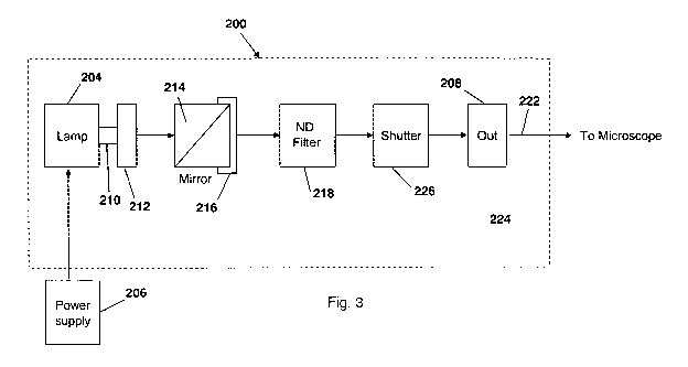
[014] Fig. 3 is a block diagram representation of another embodiment of a
light source for a microscope.
[015] Fig. 4 shows a portion of the light source of Fig. 3.
[016] Fig. 5 shows the transmission characteristic of a hot mirror used with
the light source of Fig. 3.
Description
[017] Referring to Fig. 1, a light source 100 provides light to a fluorescent
microscope 102. Light source 100 includes a 200 watt lamp 104, such as, for
example, a Model SMR-200/Dl available from USHIO AMERICA, INC.,
Cypress, CA. Lamp 104 may be a metal halide lamp. Lamp 104 provides
illumination to an optical output interface 106 which is connected to
microscope 102 via a liquid light guide 108 (e.g., a 1 meter long light guide
having a 5 mm core diameter, available from Lumatec, Deisenhofen,
Germany). Light source 100 also includes a power supply 110 that provides
power to the lamp.
[018] In one embodiment, the power level provided by power supply 110 is
regulated so that as the characteristics of lamp 104 change over time, the
power level changes such that the amount of light (measured in lumens)
provided to the optical output interface 106 is substantially constant. For
example, the amount of light emitted from lamp 104 may steadily decrease
over time. Because the decrease in lamp intensity is relatively repeatable
from
one lamp to another lamp of the same model, lamps of a particular model can
be tested to characterize their degradation as a function of time. To maintain
the same amount of light from lamp 104, the power provided to the lamp is
increased over time. Thus, the level of light intensity from lamp 104 is
relatively constant over the operational life of the lamp. Furthermore, the
operational useful life of the lamp is extended. The increase in the amount of
power provided to lamp 104 by power supply 110 is regulated by using a
controller 112. Controller 112 includes a memory 114 that tracks an amount
of time lamp 104 has been operational. Memory 114 also stores data that
- 4-
CA 02681512 2009-09-21
WO 2008/116070 PCT/US2008/057663
associates the amount of time that lamp 104 has been operational with a power
level. For example, in one embodiment the power level would increase about
2 watts for every time interval corresponding to the decrease in lamp output
over the same time interval based upon empirically collected data of lamp
degradation over time. In one embodiment, the data is stored in a table 116
having a series of time durations and corresponding power levels. The values
in table 116 are generated through the empirically collected data for each
model of lamp 104. In other embodiments, the level of light intensity from
lamp 104 is not adjusted.
[019] Controller 112 is provided with a user interface 300 that can operate in
multiple modes. User interface 300 includes a display, such as a liquid
crystal
display, to display menu screens and messages about the status of operational
parameters. User interface 300 also includes switches that a user can press to
switch between modes of operation or to enter or change operating parameters.
In one mode of operation, user interface 300 displays the operational status
of
light source 100, such as the amount of time lamp 104 has been operational.
In another mode, the user can alter operational settings of the user
interface.
For example, the user may change the volume of an audible alarm, or the
contrast or backlight level of the display. In another mode, user interface
300
operates in a diagnostic mode.
[020] Referring to Fig. 2, light source 100 shows lamp 104 optically coupled
to output interface 106 through a pair of flow adjusters 118a, 118b. Each flow
adjuster 118a, 118b has a lamp mount 120 at its downstream end. Flow
adjusters 118a, 118b are configured and positioned to maintain the
temperature across the anode and cathode of the lamp within specified
operating ranges. The flow adjuster 118a positioned closest to lamp 104
includes a fan 122 for controlling the temperature of lamp 104. Light source
100 also includes a ballast 124 that serves as a regulator. Ballast 124
consumes, transforms, and controls electrical power for lamp 104 and provides
the necessary circuit conditions for starting and operating lamp 104. Light
source 100 further includes lamp thermal sensors and ballast thermal sensors
(not shown) that monitor the temperature of lamp 104 and ballast 124,
respectively, and lamp interlocks that protect lamp 104. Light source 100 is
mounted within a housing 126 having an on/off switch 128 on a front panel
130 of the housing and an AC receptacle 132 on a rear panel 134 of the
housing. Light source 100 also has a battery (not shown) that provides power
for the light source to run in a low power mode when AC power is not
- 5-
CA 02681512 2009-09-21
WO 2008/116070 PCT/US2008/057663
provided (e.g. when the light source is turned off). The battery may be a
lithium-ion battery.
[021] Light source 100 includes a lamp sensor to detect when lamp 104 has
been disconnected from power supply 110. The lamp sensor is configured to
continuously monitor the presence of lamp 104, both when light source 100 is
turned on and when it is turned off. When the lamp sensor detects that lamp
104 has been disconnected, a lamp change status is set in memory 114. The
lamp change status remains set even if a new lamp 104 is subsequently
connected. When light source 100 is next turned on, a message is displayed
on the display of user interface 300 asking a user to confirm that a new lamp
104 has been connected. If the user confirms, controller 112 resets the lamp
change status and the amount of time that lamp 104 has been operational in
memory 114. If the user does not respond within a specified amount of time,
for example within two minutes, controller 112 may assume that a new lamp
104 has been connected and take action as if the user had confirmed. If the
user responds that the lamp is not a new lamp, the amount of time that lamp
104 has been operational is not reset and the lamp change status is reset in
memory 114.
[022] User interface 300 displays warning or error messages on the display
in the event of a warning or error condition, respectively. Warning or error
conditions are detected while light source 100 is in operation. Controller 112
also performs diagnostic tests when it is first turned on to check for the
presence of warning or error conditions. Warning conditions may include, for
example: failure of the lamp interlocks; when the lamp change status is set;
when the amount of time that lamp 104 has been operational approaches a first
preset limit, for example when the amount of time that the lamp has been
operational exceeds 1750 hours; when the amount of light emitted by lamp
104 approaches a second preset limit; when the temperature of lamp 104
exceeds a first preselected lamp temperature, for example when the
temperature of the lamp exceeds 90 C; when the temperature of ballast 124
exceeds a first preselected ballast temperature, for example when the
temperature of the ballast exceeds 55 C; or when housing 126 is open. Error
conditions may include, for example: failure of power supply 110; low voltage
in the battery; when lamp 104 is disconnected; when ballast 124 is
disconnected; when the amount of time that lamp 104 has been operational
exceeds the first preset limit, for example when the amount of time that the
lamp has been operational exceeds 2000 hours; when the amount of light
- 6-
CA 02681512 2009-09-21
WO 2008/116070 PCT/US2008/057663
emitted by lamp 104 exceeds the second preset limit; when the temperature of
lamp 104 exceeds a second preselected lamp temperature, for example when
the temperature of the lamp exceeds 100 C; or when the temperature of
ballast 124 exceeds a second preselected ballast temperature, for example
when the temperature of the ballast exceeds 70 C. When an error condition is
detected, lamp 104 and/or ballast 124 may be shut down to protect the lamp
from rupture. If any of the lamp thermal sensors, the ballast thermal sensors,
or the lamp sensor is defective or disconnected, lamp 104 and/or ballast 124
may be disabled for safety. User interface 300 can be configured to display
error or warning messages for other conditions not described herein.
[023] User interface 300 may include an audible alarm. The alarm can be
used to indicate, for example, when a switch is pressed, or the existence of
warning or error conditions. The alarm may emit sounds that correspond to
specific situations. For example, when a switch is pressed, the alarm emits a
100 millisecond beep at a low volume. For a warning, the alarm emits, for
example, a warning sequence of 3 beeps of 100 milliseconds at intervals of
200 milliseconds. This warning sequence may be repeated at 30 second
intervals. For an error, the alarm emits, for example, an error sequence of 5
beeps of 50 milliseconds at intervals of 50 milliseconds. This error sequence
may be repeated at 10 second intervals. The warning and error sequences may
be at high volume.
[024] Referring to Fig. 3, in another embodiment, a light source 200 includes
a lamp 204 driven by a power supply 206. Lamp 204 provides light to a
microscope (not shown) via an output interface 208. In this embodiment,
lamp adaptors 210 and flow adjusters 212 are used to control the temperature
across the anode and cathode of the lamp within specified operating ranges
and are shown installed between lamp 204 and a liquid light guide 222. Lamp
204 may be mounted on a baffle (not shown) in a housing and aligned with a
hot mirror 214 having the spectral characteristics described herein and placed
in the light path between the lamp and the liquid light guide. Hot mirror 214
is mounted using an angle mounting bracket 216 and secured with heat epoxy
at a desired or optimal angle for the specifications of the hot mirror. In one
embodiment of the invention, the angle of hot mirror 214 is 10 degrees
relative
to a plane normal to the lengthwise alignment of the lamp. Hot mirror 214 is
designed to reflect a significant portion of the heat energy generated by lamp
204 from the light path to maintain the liquid light guide within its
specified
- 7-
CA 02681512 2009-09-21
WO 2008/116070 PCT/US2008/057663
range of operating temperatures while still transmitting those wavelengths
that
are desired or required for the particular application.
[025] Referring to Fig. 5, in particular, hot mirror 214 transmits in excess
of
86% of the light at 340 nm for use with the fluorophore FURA and transmits
in excess of 90% of the illumination light in the visible range between 320 nm
and 680 nm. At the same time, 90% of more of light is blocked below about
320 nm and above about 680 nm, in the near infrared range and above which
are the wavelengths that carry heat. In a preferred embodiment of the
invention, the hot mirror is manufactured by a sputtering process on a Pyrex
substrate to transmit a minimum of 90% of the illumination light between 365
nm and 577 nm and having the spectral characteristics shown in Fig. 5. The
spectral characteristics of hot mirror 214 are shown in Fig. 5 and given by
the
transmission characteristics (T) below.
T at 365 nm >= 91%
T at 405 nm >= 92%
T at 436 nm >= 93%
T at 546 nm >= 93%
T at 577 nm >= 94%
[026] Referring again to Fig. 4, light source 200 can be configured to provide
for use of neutral density filters or screens 218 in the light path between
the
hot mirror and the optical light guides. One or more neutral density filters
or
screens may be mounted on a movable cartridge or carouse1220 to permit the
interchangeable use of neutral density filters or screens of varying degrees
of
transmission depending on the application. After passing through the hot
mirror and the neutral density filter or screen, if any is used, the light is
passed
to the liquid light guide 222 (Fig. 3) which is attached to the exterior of
the
housing in alignment with the lamp. A heat sink 224 to dissipate heat from the
lamp, including conducted heat, may be provided in physical association with
the liquid light guide. A movable shutter 226 to prevent accidental light
exposure and/or leakage from the housing when the liquid light guide is
removed may also be provided in the path between the lamp and the liquid
light guide. In a preferred embodiment, a copper or other metal shutter is
mounted adjacent to the attachment point for the liquid light guide at a 45
degree angle.
[027] It is to be understood that the foregoing description is intended to
illustrate and not to limit the scope of the invention, which is defined by
the
- 8-
CA 02681512 2009-09-21
WO 2008/116070 PCT/US2008/057663
scope of the appended claims. Other embodiments are within the scope of the
following claims.
- 9-