Language selection

Search

Patent 2681846 Summary

Third-party information liability

Some of the information on this Web page has been provided by external sources. The Government of Canada is not responsible for the accuracy, reliability or currency of the information supplied by external sources. Users wishing to rely upon this information should consult directly with the source of the information. Content provided by external sources is not subject to official languages, privacy and accessibility requirements.

Claims and Abstract availability

Any discrepancies in the text and image of the Claims and Abstract are due to differing posting times. Text of the Claims and Abstract are posted:

  • At the time the application is open to public inspection;
  • At the time of issue of the patent (grant).
(12) Patent: (11) CA 2681846
(54) English Title: METHOD FOR DETECTING THE PRESENCE OF A COOKING VESSEL ON AN INDUCTION COOKING HOB AND HOB USING SUCH METHOD
(54) French Title: METHODE DE DETECTION D'UN RECIPIENT DE CUISSON SUR UNE SURFACE DE CUISSON PAR INDUCTION, ET SURFACE DE CUISSON UTILISANT CETTE METHODE
Status: Granted
Bibliographic Data
(51) International Patent Classification (IPC):
  • F24C 7/08 (2006.01)
  • G01N 27/22 (2006.01)
  • H05B 6/12 (2006.01)
(72) Inventors :
  • GUTIERREZ, DIEGO NEFTALI (Italy)
  • ARIONE, ETTORE (Italy)
(73) Owners :
  • WHIRLPOOL CORPORATION (United States of America)
  • TEKA INDUSTRIAL S.A. (Spain)
(71) Applicants :
  • WHIRLPOOL CORPORATION (United States of America)
  • TEKA INDUSTRIAL S.A. (Spain)
(74) Agent: RIDOUT & MAYBEE LLP
(74) Associate agent:
(45) Issued: 2018-03-20
(22) Filed Date: 2009-10-07
(41) Open to Public Inspection: 2010-04-21
Examination requested: 2014-10-01
Availability of licence: N/A
(25) Language of filing: English

Patent Cooperation Treaty (PCT): No

(30) Application Priority Data:
Application No. Country/Territory Date
08167098.6 European Patent Office (EPO) 2008-10-21

Abstracts

English Abstract

A method for detecting the presence of a cooking vessel on an induction heating element placed below a glass surface comprises detecting through a conductive electrode placed below the glass surface if a cooking utensil is placed on the induction heating element (H) by measuring capacitance, indicating to the user whether the cooking utensil is present on one or more induction heating elements, performing a second detection of the cooking utensil, after activation by the user, by feeding power to said induction heating element (H) and by assessing at least an electrical parameter of a power circuit thereof.


French Abstract

Une méthode de détection de la présence dun récipient de cuisson sur un élément de chauffage par induction placé sous une surface en verre comprend la détection à travers une électrode conductive placée sous la surface en verre si un ustensile de cuisson est placé sur lélément de chauffage par induction (H) en mesurant une capacitance, indiquant à lutilisateur si lustensile de cuisson est présent sur un ou plusieurs éléments de chauffage, effectuant une seconde détection de lustensile de cuisson, après une activation par lutilisateur, en alimentant de lénergie audit élément de chauffage par induction (H) et en évaluant au moins un paramètre électrique dun circuit dalimentation de celui-ci.

Claims

Note: Claims are shown in the official language in which they were submitted.

7

CLAIMS
1. A method for detecting the presence of a cooking utensil on an induction

heating element (H) placed below an insulating surface (G), comprising the
steps of detecting through a sensor (10) placed below the insulating
surface (G) if a cooking utensil is placed on the induction heating element
(H) characterized in that said detection is carried out by measuring
capacitance and in that the method further comprises the following steps:
- indicating to the user whether the cooking utensil is present on one or
more induction heating elements (H),
- after the activation by the user of said indicated induction heating element

(H), performing a second detection of the cooking utensil by feeding power
to said induction heating element (H) and by assessing at least an
electrical parameter of a power circuit thereof.
2. The method according to claim 1, wherein the sensor (10) is a conductive

electrode.
3. The method according to claim 2, wherein the conductive electrode (10,
10a) is used also for supporting a temperature sensor (12) of the induction
heating element (H).
4. An induction cooking hob comprising an insulating surface (G), an
induction heating element (H) placed below said insulating surface (G), a
sensor (10) centrally placed within the induction heating element (H) and
connected to an electronic unit (16) for detecting the presence of a cooking
utensil without activating the induction heating element (H)7, wherein the
sensor (10) is a conductive electrode, characterized in that the hob is
configured to carry out the method of claim 1.
5. The induction cooking hob according to claim 4, wherein the conductive
electrode is a thermal diffuser placed between the coil and the insulating
surface (G).

8

6. The induction cooking hob according to claim 5, wherein the conductive
electrode (10) is adapted to measure a capacitance value.
7. The induction cooking hob according to any one of claims 4 to 6, wherein

the electronic unit (16) comprises a user interface for informing the user
which is the induction heating element (H) covered by a cooking utensil.
8. The induction cooking hob according to claim 4 or 6, comprising a
temperature sensor (12) supported by a metal element (10a), wherein
such metal element (10, 10a) is also the conductive electrode (10) used for
detecting the presence of the cooking utensil.

Description

Note: Descriptions are shown in the official language in which they were submitted.


CA 02681846 2009-10-07

METHOD FOR DETECTING THE PRESENCE OF A COOKING VESSEL ON
AN INDUCTION COOKING HOB AND HOB USING SUCH METHOD

This application claims priority on EP Patent Application No. 08167098.6
filed October 21, 2008, incorporated herein by reference.

The present invention relates to a method for detecting the presence of a
cooking utensil on an induction heating element placed below an insulating
surface, as well as an induction cooking hob using such method.
Nowadays all induction cooktops execute pan detection routines
immediately after the user has activated a single induction heating
element. The object of the pan detection routine is to assure that a
ferromagnetic pan is placed onto the hob in order to prevent potential
hazardous situations.

Running pan detection routines implies that power is supplied to the
heating element and therefore to the pot. Even though the power is
supplied at the minimum level possible, nevertheless the induction hob
cannot avoid heating up the pot. Furthermore, whenever the induction
power converter is activated, it generates disturbing noise at start. These
facts wouldn't be a problem if the user has placed an actual ferromagnetic
pot on the hob but, in case a pan or pot not good enough or other metallic
objects are placed onto the hob, the above known routine can heat up
uselessly and dangerously the metallic object interrupting the normal
functioning of the other heating elements of the hob.

Summing up, the drawbacks of this pan known pan detection routine are:
- energy is spent uselessly;
- there is a noisy audible "click" at start of the routine;
- power supply to the other induction heating elements of the hob that are
connected to the same induction power converter is interrupted.


CA 02681846 2009-10-07
2

Furthermore, pan detection routines might become more and more
complicated in case of induction hobs with "mixed" areas as the bridge,
multiple-coil expandable or so called "cook anywhere" configuration where
the pan can be placed in whatsoever location on the hob. These complex
s configurations might require the pan detection routine to be executed on
each different coil and then it might require an unacceptable time before
detecting the pan.

It is an object of the present invention to provide a method and a cooking
hob which solve the above mentioned technical problem in an easy and
not expensive way.

The above object is obtained thanks to the features listed in the appended
claims.
According to the invention, instead of analyzing the response of some
electrical magnitude while a certain induction heating element is activated
for detecting the pan (as done in the known pan detection routines for
induction hobs), the basic solution is to detect the ferromagnetic pan by
sensing the variation of capacitance measured under the insulating
surface, usually a Ceran glass.

Even if the general principle of detecting a pan by means of a capacitor is
known in the art of cooking appliance (for instance from EP-A-374868),
nevertheless in the art of induction cooking hobs there was a technical
prejudice which prevented the designer from adopting a further pan
detection system, being already available a detection system based on the
assessment of an electrical parameter of the induction electrical circuit.
This also prevented a man skilled in the art to solve the above mentioned
problems.


CA 02681846 2009-10-07
3

Further advantages and features of the present invention will become clear
from the following detailed description, with reference to the attached
drawings in which:
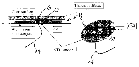
- Figure 1 is a section view and a perspective view of a portion of an
induction cooking hob according to the present invention;
- Figure 2 is a schematic view of a detail of figure 1 connected to a
user interface of the hob or to a power control board which integrates an
user interface board wherein or which communicates with an user interface
board;
- Figure 3 is a flowchart showing how the pan detection routine
according to the invention works; and

- Figure 4 is a schematic view of an induction cooking hob according
to the invention with four hob areas.

According to the drawings, a metallic electrode 10 is placed under a glass
ceramic surface G of an induction heating element H. The metallic
electrode 10 "sees" a certain capacitance (order of hundreds Pico Farads)
between the electrode and ground, according to the following general
formula:

C_6oErA
d
where:

Eo is an absolute dielectric constant;
Er is the relative dielectric constant;

A is the area of the condenser surface plate; and
d is the distance between the condenser surface plate and ground (i.e. the
cooking utensil).


CA 02681846 2009-10-07
4

This capacitance is function of the electrode area, the dielectric (for
example,
the Ceran glass), and the distance between the electrode and ground.
The capacitance is increased significantly if a metallic object is placed onto
glass surface G close to the conductive electrode 10.
The technology for sensing the capacitance on a single conductive electrode
is well known in the art of cooking appliances.
The advantages of sensing the capacitance variation under the Ceran glass G
instead of running automatically the standard pan detection routine are the
io following:
- Avoid heating up the pot uselessly.
- It is a "silent" pan detection, as the induction converter doesn't have to
be
activated.

- The sensor can be run continuously, detecting the pan whenever the user
places something on it.

- In case of complex hob configuration, it can detect quickly where might be
the
pan and which hobs is covering, avoiding time-consuming high-level
procedures.

One of the major advantages of a pan detection method according to the
present invention is to use the thermal diffusers that are placed between the
coil and the Ceran glass G in today standard induction cooktop (such diffusers
being comb-shaped or shaped in order to get a temperature signal
representative of the average temperature of the cooking utensil).
This thermal diffuser, shown with reference 10a in figure 2, must have a good
thermal contact with the safety NTC-temp sensor 12 (glass temperature
sensor) placed at coil center, but are galvanic insulated. Else more, these
known diffusers are made of electrical conductive material like aluminum. In
other words, they can works as perfect conductive electrode for a capacitive
sensing.


CA 02681846 2009-10-07

The diffuser 10a is connected with a single electrical conductive wire 14
(figure 2) to the user interface board 16 where the capacitive sensor
integrated
circuit (not shown) is placed. The diffuser 10a may also be connected to a
power control board (not shown) which integrates a user interface board
5 therein or communicates with a user Interface board. It is also possible to
use
a stand-alone electronic board with the capacitive sensor integrated circuit,
that is placed near to the thermal diffuser and that is connected via some
kind
of communication network with the user interface board
Figure 3 shows a flowchart clarifying how the zero-power pan detection
lo routine according to the invention measures continuously the capacitive
value
and interacts with the user.

According to step 18 of figure 3, if the signal from the capacitive sensor 10
is
higher than a predetermined threshold, then the user interface presents the
is user with a pre-selected heating element, eventually the pre-selected
heating
elements can be more than one depending on the induction heating elements
architecture. Then the user has to actually select one from the at least one
heating element indicated by the user interface (step 20) and to choose the
power level of such element (step 22). Only after this "double" selection the
20 procedure of hob activation is started (step 24).

It is important to point out that this new zero-power pan detection routine
doesn't replace the known standard pan detection for induction cooking hob,
rather it makes it safer, efficient and less energy consuming. Once such novel
25 routine detects a potential pan on the insulating surface, the user
interface
"proposes" to the user the activation thereof. If the user activates it, then
the
standard pan detection routine is run.

Once the new heating element has been activated, the zero-power pan
30 detection routine starts over again. It runs continuously even if no
heating
elements is activated and the UI board 16 and/or power board is in standby
mode.


CA 02681846 2009-10-07
6

Other metallic electrodes can be used with different shapes (that can be
adapted to complex hob configurations) in order to be able to detect specific
induction pan with particular shape and size.
As shown in figure 4, the electrodes can be placed inside the heating
s elements and between more that one in order to better fit the multiple zones
for induction heating. In figure 4 the cap sensors 10 are placed within the
hob
areas or between hob areas. The sensors 10 can have different shape in
order to better cover all the possible heating element zones. With the
reference A different "bridge" area are indicated, while with reference B
single
io heating elements are shown.

20
30

Representative Drawing
A single figure which represents the drawing illustrating the invention.
Administrative Status

For a clearer understanding of the status of the application/patent presented on this page, the site Disclaimer , as well as the definitions for Patent , Administrative Status , Maintenance Fee  and Payment History  should be consulted.

Administrative Status

Title Date
Forecasted Issue Date 2018-03-20
(22) Filed 2009-10-07
(41) Open to Public Inspection 2010-04-21
Examination Requested 2014-10-01
(45) Issued 2018-03-20

Abandonment History

There is no abandonment history.

Maintenance Fee

Last Payment of $263.14 was received on 2023-09-11


 Upcoming maintenance fee amounts

Description Date Amount
Next Payment if standard fee 2024-10-07 $624.00
Next Payment if small entity fee 2024-10-07 $253.00

Note : If the full payment has not been received on or before the date indicated, a further fee may be required which may be one of the following

  • the reinstatement fee;
  • the late payment fee; or
  • additional fee to reverse deemed expiry.

Patent fees are adjusted on the 1st of January every year. The amounts above are the current amounts if received by December 31 of the current year.
Please refer to the CIPO Patent Fees web page to see all current fee amounts.

Payment History

Fee Type Anniversary Year Due Date Amount Paid Paid Date
Application Fee $400.00 2009-10-07
Maintenance Fee - Application - New Act 2 2011-10-07 $100.00 2011-09-13
Maintenance Fee - Application - New Act 3 2012-10-09 $100.00 2012-10-01
Maintenance Fee - Application - New Act 4 2013-10-07 $100.00 2013-09-24
Maintenance Fee - Application - New Act 5 2014-10-07 $200.00 2014-09-23
Request for Examination $800.00 2014-10-01
Maintenance Fee - Application - New Act 6 2015-10-07 $200.00 2015-09-09
Maintenance Fee - Application - New Act 7 2016-10-07 $200.00 2016-09-07
Maintenance Fee - Application - New Act 8 2017-10-10 $200.00 2017-09-08
Final Fee $300.00 2018-02-06
Maintenance Fee - Patent - New Act 9 2018-10-09 $200.00 2018-09-12
Maintenance Fee - Patent - New Act 10 2019-10-07 $250.00 2019-09-11
Maintenance Fee - Patent - New Act 11 2020-10-07 $250.00 2020-09-16
Maintenance Fee - Patent - New Act 12 2021-10-07 $255.00 2021-09-15
Maintenance Fee - Patent - New Act 13 2022-10-07 $254.49 2022-09-01
Maintenance Fee - Patent - New Act 14 2023-10-10 $263.14 2023-09-11
Owners on Record

Note: Records showing the ownership history in alphabetical order.

Current Owners on Record
WHIRLPOOL CORPORATION
TEKA INDUSTRIAL S.A.
Past Owners on Record
ARIONE, ETTORE
GUTIERREZ, DIEGO NEFTALI
Past Owners that do not appear in the "Owners on Record" listing will appear in other documentation within the application.
Documents

To view selected files, please enter reCAPTCHA code :


To view images, click a link in the Document Description column. To download the documents, select one or more checkboxes in the first column and then click the "Download Selected in PDF format (Zip Archive)" or the "Download Selected as Single PDF" button.

List of published and non-published patent-specific documents on the CPD .

If you have any difficulty accessing content, you can call the Client Service Centre at 1-866-997-1936 or send them an e-mail at CIPO Client Service Centre.


Document
Description 
Date
(yyyy-mm-dd) 
Number of pages   Size of Image (KB) 
Cover Page 2010-04-14 1 61
Representative Drawing 2010-03-25 1 29
Abstract 2009-10-07 1 19
Description 2009-10-07 6 220
Claims 2009-10-07 2 54
Drawings 2009-10-07 2 97
Claims 2016-06-29 2 56
Final Fee 2018-02-06 3 96
Representative Drawing 2018-02-16 1 29
Cover Page 2018-02-16 1 59
Correspondence 2009-11-09 1 19
Assignment 2009-10-07 3 86
Prosecution-Amendment 2009-12-09 2 55
Examiner Requisition 2016-01-04 3 238
Prosecution-Amendment 2014-10-01 1 39
Examiner Requisition 2016-11-02 4 221
Amendment 2016-06-29 8 257
Amendment 2017-04-07 3 116