Note: Descriptions are shown in the official language in which they were submitted.
CA 02682107 2009-10-28
DEVICE FOR MANUALLY CONTROLLING DELIVERY RATE
OF A HYPODERMIC SYRINGE AND SYRINGE HAVING SAME
BACKGROUND OF THE INVENTION
Field of the Invention
The invention is related to hypodermic syringes. More specifically, the
invention
is related to devices for controlling or slowing the rate at which a
hypodermic syringe
dispenses its contents when manually operated.
Description of the Related Art
Most syringes are made of plastic. Plastic syringes are mass-produced and
disposable. A typical syringe includes a plastic barrel and a plastic plunger
having an
elastomeric seal, or stopper, at its distal end inside the barrel. The plunger
is
reciprocatable inside the barrel. The barrel typically has a pair of flanges
at its proximal
end under which the user places his index and middle fingers. The plunger
typically has
a head, or thumbpad, at its proximal end upon which the user places his thumb.
To dispense medicine contained in the syringe barrel, the user increases the
pressure applied by his or her thumb to the plunger head, while applying
opposing
(supporting) pressure with two fingers on the flanges of the barrel. Owing to
the pressure
of the thumb on the head of the plunger, the plunger advances into the barrel
and forces
the medication out via the needle. Syringe lubricant is included by the
syringe
manufacturer to allow the stopper to slide more easily within the barrel.
Polydimethyl
siloxane fluid is a typical syringe lubricant.
1
CA 02682107 2009-10-28
The benefits of disposable plastic syringes include low cost and increased
patient
safety. However, along with the benefits of plastic syringes has come an
inherent
problem: It is commonly and aptly described as "stick-slip" behavior. The
"stick-slip"
effect makes it quite difficult to inject medication slowly.
What are the benefits of slow injection? The first is comfort. Regardless of
medication, a slow injection is typically less painful than a rapid injection.
For some
medications (e.g. heparin) sudden injection can actually be quite
uncomfortable for the
patient. The second benefit of slow injection is, in some cases, better end
results,
probably owing to better assimilation of slowly injected medication by cells
in the
injected tissue. Increased effectiveness associated with slow injection rates
has been
demonstrated, for examples, in certain anaesthetic injections and in some
inoculation
procedures. In such cases the advantage to the individual patient of a slowly
delivered,
finely incremented injection include either 1) a reduced dose to produce the
same benefit
or 2) a quicker or more vigorous benefit produced by the same dose.
Slow injection offers economies of scale. In applications where it can be
shown
to produce an enhanced end result a reduced dosage might be prescribed. For an
individual patient using medicine to treat a chronic condition, injecting
daily for example,
a slight daily reduction in dosage could add up to a significant reduction in
the total
amount of medicine injected over a period of years. Similarly, in a mass
inoculation
program conducted with limited supplies of a vaccine, there could be a social
gain based
simply on the conservation of vaccine. At present, the possibilities of such
economies of
scale have not been fully explored since costly and specialized motor-driven
syringes
must be used for slow metering of injected volumes.
2
CA 02682107 2009-10-28
Why do plastic syringes make it difficult to perform slow injections? First
they
stick and then, suddenly, they slip. To start an injection, significant thumb
pressure,
called the "break out" force, must be applied to the syringe plunger to
overcome static
friction and put the plunger in motion. However, in the instant the threshold
of the
"break out" force is exceeded the plunger friction decreases dramatically and
without
warning. As a result the syringe plunger, who is still receiving very strong
pressure from
the thumb, suddenly surges into the syringe barrel.
The plastic syringe plunger's transition between "stick" and "slip" is so very
quick that the human being operating the syringe is usually incapable of
backing off the
thumb pressure in time to prevent the sudden downward surge of the plunger.
The result
is that fluid is dispensed from the syringe and into the tissue as a large
bolus, or slug, of
medication.
A slow, steadily progressing injection stroke is difficult for anyone to
achieve
with a plastic syringe, and it is especially difficult for non-professionals
who may be
required to self-inject. Stick-slip behavior is a particularly noticeable
problem if only a
few units are required to be manually injected slowly. For example, for a 5-
unit manual
injection from a 50-unit capacity U-100 type Becton Dickinson disposable
insulin
syringe, the entire injection of 5 units may be delivered in just two abrupt
surges, owing
to the stick-slip properties of the syringe. Thus, the syringe delivers to the
tissues two
successive boluses of medication, one right after the other - rather than a
slow,
incrementally metered stream.
Stick-slip behavior arises from the interaction of the elastomer used to
manufacture the syringe seal, or stopper; the syringe lubricant; and the
syringe cylinder.
3
CA 02682107 2009-10-28
To some degree, it is characteristic of all disposable plastic syringes. Stick-
slip is a
velocity dependent phenomenon, and it is most troublesome in slow injections.
In
addition to interfering with slow dispensing of medicine from a plastic
syringe, the
inherent stick-slip action of a plastic syringe makes it tricky to precisely
and
quantitatively load the syringe, particularly if fractional volume units are
desired. The
piston has a tendency to "jump" past the desired increment mark or position.
Another problem arises from the wrong kind of leverage. In the example of the
poorly controlled 5-unit injection noted above, the thumb, pivoting at a
center located at
its base joint at the wrist, quickly traverses through a tiny angular
displacement of just 2-
3 degrees in delivering a dose of 5 units. The thumb, like most anatomical
levers, is a
third class lever. It operates at a mechanical disadvantage. Muscular effort
is sacrificed in
a lever of this type in order to gain distance and, therefore, speed. The
thumb is
configured for sudden movement. A tiny angular displacement about the center
(that is,
the joint) located at the base of the thumb results in a large, sudden
displacement of the
syringe plunger by the thumbtip. The longer the thumb, the faster the thumbtip
will move
for a given angular displacement. From the standpoint of fine control and slow
injection,
this geometry is certainly not helpful. Moreover, the high breakout force
required to
overcome the molecular interaction between the elastomeric stopper and the
plastic
syringe barrel begs for an increase in mechanical advantage - not speed.
Prior efforts to ameliorate the problem include chemical modification of the
crosslinking of dimethyl siloxane syringe lubricants. The idea was to diminish
static
friction, that is, to reduce the "stick" component of the stick-slip effect.
Changing the
lubricant chemistry reportedly helped, but different medications may require
different
4
CA 02682107 2009-10-28
lubricants for optimum results. Changes in lubricant chemistry may also be
required to
optimize injections at different rates. In any event, a better lubricant is
only a small
initial step toward a solution. Lubrication can only alleviate, to some
degree, the "stick",
or static friction problem. But in a manual syringe the "slip" and the surge
injection it
produces must also be addressed.
A low cost, widely applicable solution that is independent of injection rate,
and of
the specific type of medication to be injected is needed. The inventive
solution needs to
do two things: 1) overcome the syringe's "stick", or static friction, and then
2) limit or
actively arrest the subsequent "slip" and surge.
SUMMARY OF THE INVENTION
The above and other issues are addressed by the invention, which is a device
for
mechanically/manually reducing the rate of delivery of a hand-held hypodermic
syringe
and a syringe having same. The add-on device will be referred to as an
injection retarder.
The invention controls and retards the rate of injection through the
application of second
class leverage or braking. Both effects, leverage and braking, can be achieved
with the
same device.
In one embodiment, the inventive injection retarder has a main body with a
clip
securable onto a hypodermic syringe; the main body at least partially
extending above the
barrel adjacent to a plunger of the syringe when secured to the syringe. The
injection
retarder includes means for selectively slowing a rate of progress of the
plunger into the
barrel.
CA 02682107 2009-10-28
In one embodiment, the progress slowing means includes a thumb tip rest formed
at a proximal end of the main body adapted to allow a user to place a tip of a
thumb
thereupon during dispensing of contents of the syringe. The injection is
performed by
extending the thumb, rather than flexing it as in conventional practice. As
the thumb is
extended, it rocks downward onto the syringe plunger.
When the user applies force to the head of the plunger, with the tip of the
thumb
pivoting against the thumb tip rest, force is substantially applied about an
axis through
the upper thumb joint (as opposed to joint where the thumb attaches to the
wrist with
conventional syringe usage).
In effect, the invention shifts the fulcrum of the lever (that is, the thumb)
from its
base at the wrist to the thumbtip. This fulcrum shift alters the leverage of
the thumb from
third class to second class. An example of a second class lever is a garlic
press. Second
class leverage gives the thumb a generous mechanical advantage, so that it can
very
easily overcome the inherent stickiness, or static friction, of the plunger.
It also produces
as much as a tenfold increase in the range of motion (that is, angular
displacement) of the
thumb for a given injected volume, contributing to a much improved fineness of
control.
Finally, the thumb rest anchors the thumbtip, so that the thumb does not tend
to pursue
and drive the plunger after the piston starts to slip. As a result, there is
no surge injection.
As the thumb is gradually extended and rocked downward, the injection proceeds
in a
series of tiny, incremental downward budges of the plunger. For a 50 unit
disposable
syringe with the invention in place, each incremental advance of the plunger
delivers as
little as 0.3 units of medication into the injected tissue. Thus, the
injection can be halted
at will after any 0.3-unit pulse of medication.
6
CA 02682107 2009-10-28
The thumb tip rest is preferably a flat surface onto which one places one's
thumb.
The thumb tip rest may be a substantially vertical surface extending
substantially parallel
to a longitudinal axis of the syringe barrel. In this embodiment, the thumb
tip is pressed
against the vertical surface and the first joint of the thumb is rocked
downward against
the head of the plunger to press against the plunger to dispense medicine. The
vertical
surface may be provided with a significantly higher coefficient of friction
than the rest of
the main body so the thumb tip does not slip. In addition or in the
alternative, the vertical
surface may have teeth adapted to accommodate the thumb tip of a user between
adjacent
of the teeth. Preferably, the vertical surface is sufficiently close to the
plunger so that at
least the head of the plunger is laterally pressable against the vertical
surface while the
plunger is being pushed downward into the barrel. In such a mode of operation,
the
higher coefficient of friction (or the teeth, or both) creates a resistive
force that retards the
descent of the plunger into the barrel when the user presses the head of the
plunger
against the vertical surface while pushing the plunger downward into the
barrel.
As another alternative, the thumb tip rest may be a substantially horizontal
surface
extending above the proximal end of the barrel and substantially perpendicular
to a
longitudinal axis of the syringe barrel. In this embodiment, the thumb tip is
pressed
against the horizontal surface and the first joint of the thumb is rocked
downward against
the head of the plunger.
In any of the embodiments, the inventive injection retarder may include a
plunger
stop secured to the main body and extending above the barrel and in the path
of the head
of the plunger. When a user presses down on the plunger head, the plunger
moves into
7
CA 02682107 2009-10-28
the barrel until the plunger head abuts the plunger stop. The inventive
syringe brake may
also include finger grip indentations formed in a side of the main body
opposite the clip.
In another type of embodiment, generally, the progress slowing means is a
means
for increasing a dynamic frictional force exerted by the plunger against the
force exerted
by the user in depressing the plunger. More specifically, the progress slowing
means may
include a plurality of teeth formed on one of the plunger or barrel and the
main body and
a mating tooth formed on the other of the plunger or barrel and the main body.
The
mating tooth is abuttable against the plurality of teeth when the plunger is
pressed into
contact with the main body. Pressing the mating tooth against the plurality of
teeth
creates a resistive force that retards the descent of the plunger into the
barrel when the
plunger is also pushed into the barrel. In one version, the main body is made
resilient and
biases the mating tooth against the plurality of teeth on the barrel when the
clip is secured
to the head of the plunger. Alternatively or in addition, the main body is
adapted to be
squeezed against the barrel by the user during use of the syringe.
In yet another type of embodiment, the clip is securable onto a head of the
plunger, and the progress slowing means includes at least one clamp securable
to the
barrel creating dynamic friction with the barrel as the plunger is pushed into
the barrel.
The clamp may be made resilient and be adapted to grip the barrel when secured
thereto.
Alternatively or in addition, the main body may be adapted to be squeezed
against the
barrel by the user during use.
In another embodiment, the progress slowing means includes a spring element
mechanically coupled between the plunger and the barrel. When the user exerts
a force
on the plunger to push the plunger into the barrel, the spring element tends
to resist the
8
CA 02682107 2009-10-28
user's force by generating a spring force tending to push the plunger out of
the barrel. In
this embodiment, preferably, the clip is securable to the plunger head, and a
second clip is
provided securable to a finger grip flange of the syringe. The ends of the
spring element
are preferably attached to the clips.
The invention also includes a hand-held hypodermic syringe with integral
dosage
rate control. As with conventional syringes, the inventive syringe has a
barrel and a
plunger reciprocatably movable into and out of the barrel. The inventive
syringe also
includes means for selectively slowing a rate of progress of the plunger into
the barrel.
In one embodiment, the progress slowing means includes a plurality of teeth
formed on one of the barrel and the plunger and a mating tooth formed on the
other of the
barrel and the plunger. The mating tooth is abuttable against the plurality of
teeth to
creates a resistive force that retards the descent of the plunger into the
barrel when the
plunger is also pushed into the barrel. Preferably, the plunger is made
resilient, so that
when the user presses down on the plunger, the user also presses the plunger
against the
barrel so as to press the mating tooth against the teeth. The mating tooth may
be disposed
on an exterior surface of the barrel, in which case and the plurality of teeth
may be
formed on a distally extending flange integral with the plunger.
Alternatively, the mating
tooth may be disposed on an interior surface of the barrel.
The syringe may also include a brake formed on an exterior of the barrel and a
hole formed in the barrel. The mating tooth is disposed on an end of a brake
exterior
surface of the barrel and extends into the hole to contact the plurality of
teeth on the
plunger. As an optional feature to this embodiment, a collar may be provided
at least
partially threadedly engaged with the barrel below the brake and extending at
least
9
CA 02682107 2009-10-28
partially parallel with the brake. When the collar is rotated so as to move
the collar in a
proximal direction, the collar reaches more proximally on the brake and
squeezes the
mating tooth into the hole with greater force.
Alternatively, the inventive syringe may include the thumb tip rest mentioned
above. The thumb tip rest is formed at a proximal end of the barrel adapted to
allow a
user to place a tip of a thumb thereupon during dispensing of contents of the
syringe.
When the user applies force to a head of the plunger with the tip of the thumb
pressing on
the thumb tip rest, force is substantially applied about an axis through the
upper thumb
joint. The thumb tip rest may be a substantially vertical surface or a
substantially
horizontal surface as above. In the vertical-surfaced version the thumb tip is
pressed
against the vertical surface and the first joint of the thumb is rocked
downward against
the head of the plunger. As before, the vertical surface may be provided with
a
significantly higher coefficient of friction than the rest of the syringe,
teeth adapted to
accommodate the thumb tip of a user between adjacent of the teeth, or both.
Preferably,
the vertical surface is sufficiently close to the plunger so that at least the
head of the
plunger is laterally pressable against the vertical surface while the plunger
is being
pushed downward into the barrel. In such a mode of operation, the higher
coefficient of
friction (or the teeth, or both) creates a resistive force that retards the
descent of the
plunger into the barrel when the user presses the head of the plunger against
the vertical
surface while pushing the plunger downward into the barrel.
The inventive syringe may also include a plunger stop and/or finger grip
indentations.
CA 02682107 2009-10-28
The device may be made in the form of a clip-on structure to be attached to
existing conventional syringes, or in the alternative, a syringe may be
constructed with
the device integral thereto.
The invention provides a mechanical solution to a molecular problem,
specifically, the tendency of a plastic syringe plunger to show erratic "stick-
slip"
behavior which results in an unpredictable rate of delivery of medication,
including
sudden surges. Stick slip behavior arises from the interaction of the
elastomer used to
manufacture the syringe piston, the lubricant and the syringe cylinder. In the
embodiments employing a thumb tip rest, the thumb is made to act as a second
class
lever, where the fulcrum is at one end (the thumb tip), the force is applied
at the other end
(the first distal joint), and the load (the plunger head) is in between, close
behind the
fulcrum. Second class levers of this type inherently have a mechanical
advantage of
greater than 1, because the moment arm of the force is always greater than the
moment
arm of the load. As such, it is easier to overcome the plunger's static
friction, and the
speed at which the plunger is moved is reduced. Leverage is improved, the
thumb's
range of motion per injected volume is much larger, and control becomes much
finer and
more easily applied.
The invention can be used to superimpose strong and sharply defined stopping
forces along the direction of travel of the syringe plunger, using friction
braking, direct
opposition, or clicker action to provide positive control of the plunger
movement. The
objective is to achieve a slow, incremental manual injection stroke without
requiring
complicated or expensive stepper motors or similar mechanical devices.
11
CA 02682107 2009-10-28
It is not completely necessary to manufacture new components to achieve the
invention. The inventive syringe brake can be incorporated into the
manufacture of a
syringe by slightly modifying the shapes of the moldings for the existing
syringe cylinder
and plunger. Thus, in some embodiments, the advantages can be achieved with no
additional parts or assembly steps, and no added manufacturing cost. Low
manufacturing
cost is essential for a disposable syringe.
For smaller injections, i.e., less than 10 units or so from a 50-unit syringe,
the use
of the horizontal thumb tip is adequate. For larger injections, the vertical
thumb tip rest is
preferred. Since the height of the vertical rest can be freely set or
extended, it can be
readily adjusted to accommodate the desired injection volume, up to the full
capacity of
the syringe. Large injections are performed stepwise, in 10- unit segments for
example.
At the end of each 10-unit segment, the thumbtip is re-positioned to a new
pivot point,
lower along the vertical track, and a new injection segment is then initiated.
BRIEF DESCRIPTION OF THE DRAWINGS
Fig. 1 A is a perspective drawing showing a preferred embodiment of a syringe
delivery rate control device in accordance with the invention.
Fig. 1 B is a perspective drawing of the embodiment of Fig. 1 A in a force
diagram.
Fig. 2 is a schematic illustrating the use of the syringe delivery rate
control device
of Fig. 1 with a user's thumb in a first position.
Fig. 3 is a schematic illustrating the use of the syringe delivery rate
control device
of Fig. 1 with a user's thumb in a second position.
12
CA 02682107 2009-10-28
Fig. 4 is a schematic illustrating the use of the syringe delivery rate
control device
of Fig. 1 with a user's thumb in a third position.
Fig. 5 is a schematic illustrating the use of the syringe delivery rate
control device
of Fig. 1 with a user's thumb in a fourth position.
Fig. 6 is a perspective drawing showing a second embodiment of a syringe
delivery rate control device in accordance with the invention next to a
conventional
syringe.
Fig. 7 is a perspective drawing showing the embodiment of the inventive
syringe
delivery rate control device of Fig. 6 secured to a conventional syringe.
Fig. 8 is an elevational drawing showing the embodiment of the inventive
syringe
delivery rate control device of Fig. 6 being used.
Fig. 9 is an elevational drawing showing a conventional syringe being used in
a
conventional manner.
Figs. 10A-C are perspective drawings of two versions of a third embodiment of
a
syringe delivery rate control device in accordance with the invention.
Figs. 11 A-B are perspective drawings of two versions of a fourth embodiment
of
a syringe delivery rate control device in accordance with the invention.
Figs. 12A-B are perspective drawings of a fifth embodiment of a syringe
delivery
rate control device in accordance with the invention.
Figs. 13A-B are perspective drawings of a sixth embodiment of a syringe
delivery
rate control device in accordance with the invention.
Figs. 14A-C are perspective drawings of a seventh embodiment of a syringe
delivery rate control device in accordance with the invention.
13
CA 02682107 2009-10-28
Fig. 15 is a side elevational drawing of an eighth embodiment of a syringe
delivery rate control device in accordance with the invention.
Figs. 16A-D are elevational and partial sectional drawings of a ninth
embodiment
of a syringe delivery rate control device in accordance with the invention.
DETAILED DESCRIPTION OF THE PREFERRED EMBODIMENTS
Description will now be given of the invention with reference to the attached
Figs.
1-16. It should be understood that these drawings are exemplary in nature and
in no way
serve to limit the scope of the invention, which is defined by the claims
appearing
hereinbelow.
A preferred embodiment of the invention is shown in Fig. 1 in relation to a
typical
manual hypodermic syringe 1(shown in outline). The conventional syringe 1 has
a
barrel 2, finger grips 4, and a plunger 6 having a plunger head 8.
Conventionally, the
user grasps the syringe about barrel 2 between his index and middle fingers
just below
finger grips 4. The user then places his thumb atop plunger head 8. When the
user
squeezes his thumb and first two fingers together, the two fingers press under
finger grips
4 and the thumb pushes plunger 6 downward into barrel 2, thereby dispensing
the
contents of the syringe. As described above, this process is adversely
affected by the
"stick-slip" effect at slow injection speeds, and a large bolus of medicine is
delivered all
at once. It would be more desirable to administer medicines at a slow, even
rate. Device
of Figs. 1-5 enables the user to accomplish this objective through increased
leverage,
oppositional braking, or both.
14
CA 02682107 2009-10-28
The inventive device 10 is attachable to an existing syringe 1 in the manner
shown in Fig. 1. Device 10 has a main body 12 which may be formed as a single
piece of
plastic or similar material. Body 12 includes a clip 14 which has at least one
(but
preferably a pair of) resilient arms 15. Arms 15 have a curved interior hollow
specifically adapted for receiving the exterior of barrel 2 of syringe 1.
Different sized
clips 14 may be created to accommodate different sized barrels 2, however if a
single size
of clip 14 is manufactured, it is likely that it can be made sufficiently
resilient to
accommodate most standard sizes of barrels. As shown in Fig. 1, barrel 2 is
inserted into
clip 14 so that finger grips 4 are above clip 14. Plunger stop 16 also extends
from main
body 12 above clip 14. The primary function of plunger stop 16 is to prevent
plunger 6
from entering barrel 2 beyond a specific point. Thus, when the plunger is
being
depressed (to be described below), plunger head 8 will at some point abut
against plunger
stop 16 and will prevent plunger 6 from further downward travel into barrel 2.
Disposed on the opposite side of main body 12 from clip 14 are finger grips 18
which allow the user to grasp the device more comfortably and securely during
use.
Every embodiment of the invention includes some mechanism for gaining better
control of (and thus slowing) rate of progress of the plunger into the barrel.
This is
conceptually accomplished in one of at least two ways. First, as shown in Fig.
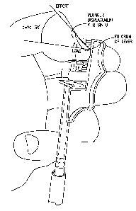
1 B, the
mechanical advantage of the thumb is greatly increased by shifting the fulcrum
of the
thumb from the third distal joint to the thumb tip, thereby making the moment
arm of the
load (the distance from the plunger head to the thumb tip) much shorter than
the moment
arm of the effort (from the tip to the first distal joint) and shortening the
distance the load
travels (letter y in Fig. 1 B). In other words, the invention enables the user
to use his
CA 02682107 2009-10-28
thumb as a second class lever instead of a third class lever as with
conventional injection
techniques.
In addition or in the alternative, the dynamic frictional resistance of the
plunger
may be increased to make it closer to (or equal to or greater than) the static
frictional
resistance of the plunger (i.e., the friction caused by continuing to move the
plunger will
be increased with respect to the static friction needed to be overcome just to
begin to
move the plunger).
In the preferred embodiment, shown in Figs. 1-5, main body 12 includes a
vertical
surface 20 which may be used to slow the rate of progress of the plunger in
either of the
two ways listed above. As shown in Fig. 1, vertical surface 20 is preferably
provided
with teeth 22, between adjacent of which are troughs 24. In addition or in the
alternative,
vertical surface 20 may be provided with a "no-skid" coating or layer which
has a
significantly higher coefficient of friction than the rest of main body 12. In
the preferred
mode of operation, as shown in Figs. 2-5, the user presses the tip of his
thumb against
vertical surface 20, more preferably in a trough 24. The first distal joint
DJl of the
thumb T is preferably angled as shown in Fig. 2. The ball of the thumb is
positioned atop
plunger head 8. The user's first, second, and/or third fingers F 1-F3 are
preferably
positioned in finger grips 18. When it is desired to dispense the contents of
the syringe,
the user pivots the most distal phalange about the first distal joint DJ1 of
the thumb T
only while maintaining contact against vertical surface 20. The result is that
the proximal
end of the first distal joint (i.e., substantially at the first knuckle) moves
downward,
pressing against the plunger head. The end of this motion is shown in Fig. 3
as arrow A.
Note that this downward rolling motion is produced by the extension of the
first phalange
16
CA 02682107 2009-10-28
of the thumb, as opposed to the flexing of the entire thumb used
conventionally to empty
a syringe.
Since the moment arm of the force being generated (from DJl to thumb tip) is
now much greater than the moment arm of the load being moved (from thumb tip
to
plunger head), there is greater mechanical advantage of the thumb and much
less plunger
movement and speed as compared to conventional syringe usage, thereby allowing
the
user to move the plunger in a much finer fashion and have far greater control
over its
movement.
The thumb tip may be re-placed at a different location on vertical surface 20
(e.g.,
where the plunger stopped at the end of the first "roll"), as shown in Fig. 4,
and the
above-described "rolling" motion of the first joint of the thumb would be
repeated to
dispense additional medicine. The end of the second roll is shown in Fig. 5.
The process
is repeated until the desired amount of medicine is dispensed or until plunger
8 abuts
against plunger stop 16 (see Fig. 1).
The embodiment of Figs. 1-5 may also be used in the other manner of the
invention, i.e., to increase the dynamic frictional resistance of the plunger
to make it
closer to (or equal to or greater than) the static frictional resistance of
the plunger. It may
be tempting for the user to simply press plunger head 8 against vertical
surface 20 in the
direction of arrow B of Fig. 1 while pressing downward on plunger head 8 at
the same
time. Whether vertical surface 20 is provided with a "no-skid" high friction
layer or
teeth 22 (or both), dragging the side of plunger head 8 against vertical
surface 20 while
pushing it downward into the barrel greatly increases the resistive force of
the plunger.
Opposition to the motion of the plunger slows and limits the runaway motion of
17
CA 02682107 2009-10-28
the plunger induced by the stick slip effect. As a result, the motion of the
plunger may be
finely controlled. One advantage of this method of using the device is that,
when teeth
are provided, the plunger head will "click" as it passes over each tooth,
providing an
audible and tactile signal to the user. Each tooth brings the plunger to a
decisive halt, and
may be used as a way of metering out, in pulses, very small aliquots of
medicine. The
plunger may be stopped after passing over a predeterminable number of teeth.
Dosage
markings may be made on teeth 22 or on main body 12 near troughs 24 so that
the dosage
may be precisely loaded, monitored and delivered.
As shown in Fig. 1, injection retarder 10 is preferably a clip-on device
attachable
to a conventional plastic syringe. Injection retarder 10 is preferably made as
a single
piece of plastic, however other materials are contemplated. It is preferred
that at least
clip 14 be made from a resilient material (such as plastic) so that it may be
snapped onto
the barrel and stay put. Rack 20 may, in other embodiments, include any non-
skid
surface, that is, a surface offering an increased coefficient of friction.
Several effective
no-skid surfaces may be created from carborumdum paper, polyisoprene with
molded-in
teeth, smooth polyisoprene, or a rubberized, knurled, or otherwise roughened
surface of
essentially any material The non-skid surface can be molded or machined into
the
device, or attached to it. The toothed surface is superior, because of its
predictable and
reliable escapement action in arresting the syringe plunger 6 after each
incremental
injection of medication.
Figs. 6-8 depict an alternate embodiment of the inventive injection retarder
10.
This embodiment offers only enhanced leverage; no braking is available. In
Figs. 6-8,
injection retarder 110 is configured slightly differently than brake 10. Clip
114 is
18
CA 02682107 2009-10-28
securable around barrel 2 of a syringe, and injection retarder 110 is provided
with
channel 115 into which syringe finger grip flanges 4 are disposable. As
before, a plunger
stop 116 is provided to delimit the range of motion of plunger 6 into barrel
2. The chief
difference between injection retarder 10 and injection retarder 110 concerns
the surface
upon which the user rests or presses his thumb. In brake 10, the surface is
vertical
surface 20. In injection retarder 110, the relevant surface is horizontal
surface 120. As
shown in Fig. 8, the user places the tip of his thumb atop horizontal surface
126 and
angles his first distal thumb joint upwards. The ball of the user's thumb is
placed on
plunger head 8. The user then pivots his thumb joint downward in the direction
of arrow
A as shown in Fig. 8 (it is substantially the same movement as shown in Figs.
2-5). The
angular movement of the first distal joint during this movement is
approximately 25-30E.
By contrast, if the user were to inject himself (or another) via the
conventional method
shown in Fig. 9 without the invention, the entire thumb becomes the lever arm
for the
force around where the thumb connects to the wrist, and the angular movement
is only
about 2-3E. Thus, as mentioned above, by moving the fulcrum, much finer
control of the
movement of the plunger is realized. The end 126 of horizontal surface 120 is
curled
downward to avoid a sharp edge and minimize the risk of a cut or abrasion.
The embodiment of Figs. 6-8 is preferably made as a single piece and can be
made from either sheet or stamped metal or molded plastic. In this embodiment,
clip 114
is preferably resilient so that it may be snapped onto the barrel and stay
put.
In using both devices 10 and 110, the first distal joint of the thumb swings
downward from a pivot point which is positioned, by the invention, in front of
the
19
CA 02682107 2009-10-28
syringe body. Thus, the pivot point used in dispensing medicine is now moved
vastly
forward by using the invention of the above embodiments. On a conventional
syringe,
the thumb pivots from a joint at the wrist. In devices 10 and 110, the thumb
pivots from
a point on surface 20 (or 120), a point just ahead of the syringe body. One
purpose of
moving the fulcrum to a point ahead of the syringe body is to increase the arc
swept by
the first knuckle of the thumb as it depresses the plunger of the syringe.
This makes it
much easier to slowly dispense medication from the syringe. The class of the
lever
represented by the thumb is also changed by shifting the fulcrum to the
thumbtip. Using
a conventional syringe in the conventional manner is using the thumb as a
third class
lever, analogous to a mousetrap. A third class lever is configured for speed,
and thus has
a mechanical advantage of less than 1. In contrast, use of the inventive
device on a
syringe enables the thumb to act as a second class lever, e.g., like a garlic
press or nut
cracker. A second class lever has excellent mechanical advantage and moves the
load (i.e.
the plunger) slowly.
The basic functioning of the above embodiments is depicted in Fig. 1 B and is
representable by the following equation:
y=r sin0 (1)
where
y is displacement
r is the radius
and 0 is the angle.
As long as distance between the pivot point and point at which power is
applied to the
plunger is kept very short (meaning, the radius, r, is kept short) it does not
matter from
CA 02682107 2009-10-28
where on the thumb one chooses to pivot. If r is small, the displacement, y,
will be kept
small, and the plunger will move slowly.
There exist four possible pivot points for the thumb - the tip, the first
knuckle
(from the nail), the second knuckle, and the socket point at the wrist. A
point selected
near any of these joints, or pivots, could theoretically be used the drive the
syringe
plunger. There are four fundamental reasons to use the invention and choose
the thumb
tip: opposition, dosage, visibility, and repeatability.
Opposition. Opposition or bracing for the thumb is essential because of the
stick-
slip effect. Opposition helps the thumb quickly stop itself. It keeps the
"slip" from
turning into a runaway slide, delivering a 2-unit or larger bolus. In the
above
embodiments of Figs. 1-8, surfaces 20 and 120 provide serve both as a pivot
and a flat
surface secured to the syringe against which to brace the thumb. When the user
overcomes the stiction, the thumb does not translate this release into a surge
of
medication, thanks to the solid opposition of the mechanical stop against
which the
thumb tip is constantly pushing.
Dosage and pivot shifting. The thumb tip is free, while the three other
possible
pivots are inhibited in their mobility, especially the wrist socket. The thumb
tip can be
placed in any convenient location. This is important because for a large dose,
it is
necessary to change pivot points in the course of the injection, as shown in
Figs. 2-5.
Freehand methods might work adequately for small doses, which can be
accomplished at
one squeeze, but not for doses of greater than about 8 units from a 50-unit
syringe. This
is because to accommodate a large dose (25 units, say) you need to be able to
move the
pivot point. This is easy to do with a thumb tip fulcrum and a vertical
surface (e.g.,
21
CA 02682107 2009-10-28
surface 20). The user simply moves the thumb tip down the runway to establish
a fresh
pivot point, from time to time, as the injection plunger progresses downward.
By
contrast, it is not easy to use the first or second knuckle as the chosen
pivot by, perhaps,
shifting the syringe in one's hand in order to follow a long plunger stroke to
its
conclusion. It is very undesirable to manipulate the syringe much after the
needle has
been planted in tissue.
Visibility. Devices 10 and 110 can be clipped onto the syringe in such a way
that
the graduation marks on the syringe barrel can be easily read and the progress
of the
injection can be easily monitored. This is difficult if the syringe is gripped
deep inside
the user's hand, as it would have to be if one were to position the plunger at
one of the
other possible pivot points.
Precision and repeatability. The inventive surface for the thumb tip pivot is
precisely positionable, using manufacturing techniques such as molding or
machining, so
that the radius, r, is kept very small. As a result the injection procedure as
performed
with the invention is reliably slow and repeatable.
In terms of slowing down the plunger, and thus the rate of injection, the
performance of device 10 with the vertical surface 20 is superior to that of
device 110.
This is because the vertical surface can be positioned very close to the
plunger,
minimizing the radius, r, and thus the displacement, y. The thumbnail inserted
between
the teeth of device 10 provides an excellent pivot and an anchor against
runaway
injection. In addition, with device 10 the force of the thumb is directed
forward, rather
than downward in the direction of travel of the plunger. This also helps
prevent
uncontrolled surges. Instead, the plunger moves downward in a succession of
tiny
22
CA 02682107 2009-10-28
budges, and these budges effectively demark the increments of injected volume.
One can
decisively halt the injection after any such incremental volume, or pulse, has
been
delivered to the tissues. This is important because one way to judge the
success of the
invention is to ask how little medication can be injected before the plunger
can be
brought to a halt. Recall that in a conventional injection from a 50-unit
insulin syringe,
the smallest volume that can be fairly repeatably delivered to the tissues was
a slug of
about 2.5 to 3.0 units.
Experimentally, using a 50-unit capacity syringe, it has been determined that
device 10 can be used to inject medication in incremented pulses as small as
0.3 units,
while device 110 has been able to inject a succession of incremented pulses as
small as
0.5 units. In either case, this is a very substantial improvement on the 2.5-
unit surges
delivered in an uncontrolled manner when the same syringe is used
conventionally.
Many other forms of the inventive syringe brake are contemplated. For example,
Figs. 1 OA-C depict injection retarder 210 having a short, substantially
cylindrical main
body 212 that is securable onto the proximal end of barrel 2 (se Fig. l OB).
The interior of
main body 212 may be provided with ribs 213 for creating a friction fit with
the end of
the barrel; alternatively, threads could be provided for screwing injection
retarder 210
onto a customized barrel having mating threads (not shown). An engaging pawl
or tooth
228 is formed on main body 212 projecting inward towards the center where the
plunger
would be disposed. As shown in Fig. l OB, brake 210 is preferably used with a
customized plunger 206 having teeth (or knurling) 224. In operation, plunger
206 is
pressed sideways against tooth 228 in the direction of arrow C while it is
depressed into
barrel 2 in the direction of arrow D. The increased frictional resistance
caused by teeth
23
CA 02682107 2009-10-28
224 dragging over tooth 228 slows the progress of the plunger. The transition
from tooth
to tooth arrests the "slip" of the plunger, limiting and defining the volume
that can be
delivered with each incremental downward move of the plunger. The spacing of
the teeth
can be set to correspond to some useful increment of injection volume, e.g.,
0.3 or 0.5
units. This movement also produces a clicking sound and tactile feedback,
which can aid
the user in metering out dosages of medicine. Fig. l OC shows an alternative
embodiment
in which tooth 228 is formed integrally with barrel 202. All of the same
principles
enumerated above with the previous embodiment apply to the Fig. l OC
embodiment.
Figs. 11 A-B depict another clicker-style braking embodiment formed integrally
with the syringe. Plunger 206 includes teeth 224, however the barrel includes
a curved
brake 238 which extends past the proximal end of the barrel. Again, plunger
206 is
pressed against brake 238 in the direction of arrow C while being depressed
into the
barrel in the direction of arrow D. In Fig. 1 lA, brake 238 extends from the
side of barrel
202A at its proximal end, e.g., from near the finger grip flanges 4. In Fig.
11B, brake 238
extends directly out of the top of barrel 202B. Brake 238 may be made of
resilient plastic
or metal to be biased towards plunger 206.
Figs. 12A-B depict a clip-on version of the Fig. 11 embodiment. Main body
212A is somewhat S-shaped in cross section and, as shown in Fig. 12B, is
disposable on
top of finger grip flanges 4. This embodiment may be made from plastic or
sheet or
stamped metal.
Injection retarder 310 is depicted in Fig. 13. In Fig. 13A, clip 314 is formed
at
one end of main body 312 and is adapted to be secured onto plunger head 8. At
the other
end of main body 312 are formed teeth or knurling 324 which are adapted to
engage an
24
CA 02682107 2009-10-28
annular brake or tooth 328 formed on barrel 302. Main body 312 may be curved
and
made from a resilient material so that when clip 314 is secured onto plunger
head 8, teeth
324 are naturally pressed against annular tooth 328. A similar embodiment,
injection
retarder 310A, is shown in Fig. 13B. Here, main body 312A includes a distal
barrel
gripper 327 which fits around the barrel of a plunger. In the embodiment shown
in Fig.
13B, tooth 328A engages teeth or knurling 324A formed on barre1302A. Barrel
gripper
327 may be made from a resilient material and dimensioned to fit snugly on the
barrel to
insure the engagement of tooth 328A and teeth 324A. In the alternative or in
addition,
the user may squeeze barrel gripper 327 in the direction of arrows E to
increase such
engagement and therefore the frictional resistance thereof. Fig. 14 depicts a
simpler
embodiment 310B which may be secured to and work on conventional syringes.
Here,
barrel gripper 327 may be resilient and/or squeezed as before to increase the
sliding
friction between it and barrel 2. Figs. 14B and C depict two of the many
different shapes
this embodiment may take.
There are two ways to use a device of the type shown in Fig. 14. One is to
squeeze the clip against the body of the syringe barrel to create, and vary,
dynamic
friction braking to control and retard the descent of the plunger. The other
method is to
place opposed fingers on the barrel, so that one or more fingers lie directly
in the path of
the clip, and let the clip "bulldoze" the fingers. The fingers, by opposing
the progress of
the clip, can provide direct muscular opposition to the downward force of the
thumb on
the plunger.
In all of the embodiments for clicker action described above, the toothed
surface
may be replaced with a high coefficient of friction surface. This can be
accomplished by
CA 02682107 2009-10-28
shaping (as by knurling) or by layering with a higher friction material (e.g.,
polyisoprene), or both.
Fig. 15 depicts another embodiment of the inventive plunger progress slowing
mechanism. Here, brake 510 includes a spring element 517 mechanically
connected
between the plunger and barrel of a syringe. In the drawing, one end of spring
element
517 is attached to a clip 514 which is securable to plunger head 8, while the
other end is
attached to clip 515 which is securable to finger grip flange 4. As the
plunger is
depressed, the spring element generates a resistive force in the opposite
direction, tending
to resist the progress of the plunger into the barrel. Other connective
structure may be
employed.
Figs. 16A-D depict a variety of modified syringes that have plunger progress
slowing mechanisms built integrally therein. Fig. 16A depicts a syringe having
a
modified plunger 506 having plunger head 508 with a downwardly extending
flange 509.
The distal end of flange 509 is provided with teeth or knurling 524; barre1502
is provided
with a mating tooth or paw1528 on its exterior. Flange 509 may be made from a
resilient
material so that it is biased against tooth 528. Alternatively or in addition,
the user may
squeeze flange 509 against tooth 528 during use. Fig. 16B illustrates a
similar
embodiment having teeth 524A formed on plunger 506A, and tooth 528A formed on
the
interior of barrel 528A. Fig. 16C shows another embodiment having brake 527
integrally
formed with barrel 502B. Tooth 528B protrudes through a hole in barrel 502B to
engage
teeth 524A on plunger 506A. Indicia 503 may be printed on plunger 506A to
assist in
dosage metering. Fig. 16D adds a collar 540 which can adjust the amount of
pressure
brake 527 places on teeth 524A. Collar 540 includes threads 542 which engage
mating
26
CA 02682107 2009-10-28
threads 544 on the exterior of barrel 502B. When collar 540 is rotated, is
moves along
arrow G; the further in the proximal direction the collar is moved, the
tighter it squeezes
brake 527, and the greater the frictional force between the brake and the
teeth will be
generated.
The invention is not limited to the above description. For example, Figs. 1-5
show a substantially vertical thumb tip support surface, and Figs. 6-8 show a
substantially
horizontal thumb tip support surface. However, an angled support surface
(i.e., an angle
between OE, or horizontal, and 90E, or vertical) may be employed without
departing from
the scope of the invention. In addition, one may apply both leverage and
braking action
to the relative motion of the syringe barrel 2 and the plunger 6. This can be
accomplished
by judiciously combining on a single syringe more than one of the embodiments
discussed above. For example, one can combine the leverage-only device of Fig.
6 with
the clicker device of Figs 16C or D.
Further, any descriptions of manufacturing processes are not meant to be
limiting
but merely exemplary and demonstrative. Also, while some embodiments are shown
as a
clip-on device attachable to a conventional syringe and others are shown as
integral to a
modified syringe, it should be understood that any of the clip-on structures
may be
integrated into a modified syringe, and any of the modified syringe structures
may be
utilized in a clip-on device.
Having described various embodiments of the invention, it should be understood
that the invention is not limited to the above description or what is shown in
the
drawings. Rather, the invention is defined by the scope of the claims
appearing
hereinbelow and their equivalents to those of ordinary skill in the art.
27