Note: Descriptions are shown in the official language in which they were submitted.
CA 02682201 2012-11-06
WO 2008/116051
PCT/US2008/05726
PROSTHETIC DEVICE UTILIZING ELECTRIC VACUUM PUMP
Inventors: James M. Colvin
Michael L. Haynes
Christopher T. Kelley
Mark W. Ford
Mark W. Groves
Jeffrey A. Denune
BACKGROUND OF THE INVENTION
[0001] The present invention is directed to electrically-powered evacuation
devices for use in evacuating a prosthetic socket and/or to prosthetic limbs
incorporating such electrically-powered evacuation devices. The present
invention is also directed to various systems and methods for configuring,
monitoring, performing, adjusting and controlling such devices.
[0002] Artificial limbs have been in use throughout history, having been
first recorded circa 2750 B.C. During that period of time, interfacing and
suspending an artificial limb has been a continuing challenge. Various and
numerous theories and anatomical constructs have been used over time in an
evolving manner, and these have revealed a number of key factors in
maximizing comfort and functional potential for persons who wear artificial
limbs.
[0003] Firstly, the surgical procedure used to perform limb amputation is
an important factor. The size and shaping of the patient's residual limb is
1
CA 02682201 2009-09-18
WO 2008/116051
PCT/US2008/057625
often important to the comfort the patient will later have with a prosthesis.
Stated simply, it is critical that the residual limb and prosthesis interface
tightly
and couple and distribute pressure evenly across the surface of the residual
limb.
[0004] Early versions of artificial limbs required the use of leather or
equivalent straps or belts to suspend the artificial limb upon the person.
Later
systems employed linkage techniques such as condylar wedges, rubber or
synthetic elastic tubing, thermoplastic roll-on sleeves with pin locking
systems,
and sub-atmospheric pressure. Of these, sub atmospheric pressure is
typically often preferred, because it creates a linkage that provides maximum
proprioceptive feedback and control for the artificial limb user. It also
provides
the best linkage between the user's limb and the prosthetic device.
[0005] Creating a reliable sub atmospheric pressure chamber between the
residual limb and prosthetic device has, however, proved to be a challenge.
As new airtight thermoplastic and thermo set materials have evolved, along
with airtight thermoplastic roll-on liners, the potential for creating a sub-
atmospheric pressure within the prosthetic chamber (socket) has improved.
Specifically, the patient's residual limb is covered with a roll-on urethane,
silicone, or other thermoplastic or theromoset liner, which helps to protect
the
user's tissue from unwanted isolated high negative pressure values, and
provides cushioning for the tissue at the same time. The liner also helps to
distribute the sub-atmospheric pressure applied to the user's limb in a more
uniform manner.
2
CA 02682201 2009-09-18
WO 2008/116051
PCT/US2008/057625
[0006] Several mechanical means for creating an elevated negative
pressure chamber within a prosthetic socket have emerged. One method
disclosed in U.S. Patent 6,554,868, utilizes a weight activated pump, in which
sub atmospheric pressure is maintained strategically within the socket as the
user walks. Under this approach, vacuum is maintained as the patient
ambulates with the artificial limb.
[0007] This method of evacuating a prosthetic socket has several
disadvantages, however. First, the weight activated pump is heavy, and
cannot be removed even in the case of a pump failure. The weight activated
pump also requires a certain minimum space between the user's limb and
prosthetic foot, which may be more than is available if the patient has a
relatively long residual limb. This prohibits the use of this technology for
many
artificial limb users. Further, a weight-activated pump system requires some
number of weight activated strokes before becoming effective.
[0008] Another evacuation method disclosed in the above-referenced
patent uses a hand-held sub-atmospheric pressure pump, much like that used
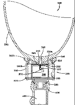
to bleed brake systems on an automobile. This method provides for
acceptable socket evacuation, but requires the individual to carry the hand-
held pump upon their person for use in case of vacuum failure. The hand-
held pump is also awkward for many individuals to use and requires a certain
amount of dexterity and strength to operate. This is a common problem for
elderly individuals.
3
CA 02682201 2009-09-18
WO 2008/116051
PCT/US2008/057625
[0009] As can be understood from the foregoing discussion, known
mechanical systems for evacuating a prosthetic socket have several
disadvantages. Aside from those specific disadvantages detailed above, such
mechanical systems are further burdened with other general problems.
Primarily, the evacuation pump associated with such systems is active only
when the user is ambulating, and then is activated with every step -
regardless of the wishes of the user.
[0010] Therefore, one general disadvantage to such a mechanical systems
is that the pump is unable to draw vacuum when the user is sedentary. This
means that absent the carrying and use of a separate hand-held pump, there
is no way to properly don an associated prosthesis without standing up and
walking on the prosthesis in a partially donned (i.e., non-evacuated) state.
Similarly, if the socket loses pressure while the user is sitting or otherwise
non-ambulatory, there is no way (aside from a separate hand-held pump) to
re-evacuate the socket other than walking or bouncing on the now improperly
suspended prosthesis.
[0011] Another disadvantage to such mechanical evacuation systems is
that a weight-activated pump will always eventually evacuate the prosthetic
socket to some predetermined level. As such, there is no way for a user to
adjust the level of vacuum to coincide with a particular activity or comfort
level. For example, a user would not be able to increase the vacuum level
over some typical vacuum level during a period of increased activity, nor
4
CA 02682201 2009-09-18
WO 2008/116051
PCT/US2008/057625
decrease the vacuum level to compensate for a particularly sore or sensitive
residual limb.
[0012] Yet
another disadvantage to known evacuation systems is that they
tend to be bulky, unattractive, and difficult to cosmetically finish. For
example,
it may be difficult or impossible to apply a cosmetic cover that imparts a
lifelike
appearance to a prosthesis because the evacuation device may be too bulky.
Also, applying a cosmetic cover may interfere with the function of the
evacuation system or may prevent or discourage recommended access to the
evacuation system.
[0013] Thus,
there is a need for improved means of achieving sub-
atmospheric pressure within a prosthetic socket. The present invention
satisfies this need.
SUMMARY OF THE INVENTION
[0014] The
present invention overcomes the disadvantages inherent to
known prosthetic socket evacuation devices using mechanical (e.g., weight-
activated) pumps. Rather,
the present invention is directed to socket
evacuation device employing an electrically-activated pump. Because the
electrically-activated pump does not require manual manipulation to create
vacuum, it is substantially easier to use than a manual pump. Further, due to
the compact size and minimal power consumption associated with an
evacuation device of the present invention, it may be readily incorporated
into/onto a prosthesis.
CA 02682201 2009-09-18
WO 2008/116051
PCT/US2008/057625
[0015] A device
of the present invention thus affords substantial general
advantages over the manual pumps and gait-driven pumps of the prior art,
and the inventors are believed to be the first to present a practical approach
to
providing an electrically evacuated prosthetic device. The '868
patent
referenced above suggests the inclusion of a generically drawn "vacuum
source" and "power source", and a regulator for automatic vacuum
maintenance, into an outer socket of a prosthesis (see, e.g., Figs. 7 and 9
and
discuss thereof); however, there is no specific reference therein to a vacuum
source or power source that is of suitable size and weight for such an
application, as is provided by the inventors hereof. The present invention
thus
represents an advance and an enabled approach to providing an electrically
actuated, portable vacuum pump in a prosthesis.
[0016] An
electrically-activated evacuation device of the present invention
offers additional advantages not possible with a manual or gait-driven device.
For example, in addition to embodiments wherein the vacuum level is directly
controlled by the user, the present invention may also possess semi-
automatic or automatic vacuum level control and/or semi-automatic or
automatic vacuum regulation.
[0017] Yet
another advantage of an electrically-activated evacuation
device of the present invention is that it can be made to blend in with the
rest
of a prosthesis, and can actually be integrated into the prosthesis - making
it
much easier to cosmetically finish the prosthesis, if so desired. Even in an
6
CA 02682201 2013-10-17
WO 2008/116051 PCT/LIS2008/05726
embodiment using wireless capabilities, applying a cosmetic cover will not
interfere with
the function of the evacuation system.
[0017b1 In one aspect, the present invention provides a wireless control
system for
controlling a vacuum control assembly associated with an evacuation device
located on
or in a prosthetic limb device for maintaining the prosthetic limb device in
communication
with a residual limb. The evacuation device comprises: a power source for
providing a
power supply, a microprocessor, a vacuum pump in communication with the
microprocessor, a pressure sensor in communication with the microprocessor, a
wireless
transceiver in communication with the microprocessor, and a regulator in
communication
with the microprocessor. A hand held controller adapted for wireless
communication with
the vacuum control assembly is provided where the hand held controller
comprises: a
power source for providing a power supply, a microprocessor, a wireless
transceiver in
communication the respective microprocessor, a regulator in communication with
the
respective microprocessor, and wherein the hand held controller can be used to
control
the evacuation device via wireless communications with the vacuum control
assembly.
In some embodiments, timing crystals are provided each in communication with
the
respective microprocessors. Furthermore, in some embodiments, the regulators
associated with the microprocessors of the evacuation device and the hand held
controller each have respective enable pins.
[0017c1 In another aspect, there is provided a wirelessly controllable vacuum
control
system. The system includes an evacuation device located on or in a prosthetic
limb
device for maintaining the prosthetic limb device in communication with a
residual limb
7a
CA 02682201 2013-10-17
W020081116051 PCT/US2008/05726
where the wirelessly controllable vacuum control system has an associated hand
held
controller, The wirelessly controllable vacuum control system comprises a
power source
for providing an evacuation device power supply to an evacuation device vacuum
pump,
an evacuation device pressure sensor, an evacuation device regulator and an
evacuation
device wireless transceiver, each of which in coordinatable communication with
an
evacuation device microprocessor. The evacuation device microprocessor is
responsive
to wireless communication from the associated hand held controller and the
associated
hand held controller includes a hand held controller power source for
providing a hand
held controller power supply to a hand held controller wireless transceiver
and a hand
held controller regulator, each of which in communication with a hand held
controller
microprocessor. The associated hand held controller is adapted for wirelessly
controlling
the evacuation device to effect maintaining the prosthetic limb device in
communication
with the residual limb.
10017d] In some embodiments, the evacuation device microprocessor and the hand
held regulator in communication with the hand held controller microprocessor
each have
respective enable pins,
[0017e] In some embodiments, the evacuation device wireless transceiver is
integrated
into the evacuation device microprocessor or the hand held controller wireless
transceiver is integrated into the hand held microprocessor and in further
embodiments
the evacuation device wireless transceiver and the held controller wireless
transceiver
are each respectively integrated into the evacuation device microprocessor and
the hand
held controller microprocessor.
7b
CA 02682201 2013-10-17
= WO 2008/116051 PCT/US2008/05726
[0017f] In some embodiments the associated hand held controller is a fob.
[0017g] In some embodiments the associated hand held controller includes a
display and in further embodiments the display is of the LCD variety.
[0017h] in some embodiments the evacuation device power supply is self-
latching or
the hand held controller power-supply is self-latching. In further
embodiments, both the
evacuation device power supply and the hand held controller power supplies are
self-
latching.
[00171] In some embodiments, there is a pushbutton associated with the
evacuation
device regulator and/or a pushbutton associated with the hand held controller
regulator.
In some embodiments there is an output of the pushbuttons connected to an
input of its
associated microprocessor.
[0017j] In some embodiments, the evacuation device is shut down by the
evacuation
device microprocessor when the evacuation device microprocessor is inactive
and/or the
associated hand held controller is shut down by the hand held controller
microprocessor
when the hand held controller microprocessor is inactive.
[0017k] In some embodiments, the wirelessly controllable vacuum control
system,
further comprises evacuation device peripheral devices associated with the
evacuation
device and/or hand held controller peripheral devices and wherein the
evacuation device
peripheral devices and/or the hand held controller peripheral devices are
turned off by
evacuation device peripheral device microprocessors and/or hand held
controller
peripheral devices microprocessors when the evacuation device peripheral
device
7c
CA 02682201 2013-10-17
WO 2008/116051 PCT/US2008/05726
microprocessors and/or hand held controller peripheral devices microprocessors
the
evacuation device microprocessor are inactive,
[001711 In some embodiments, the wirelessly controllable vacuum control system
includes a timing crystal in communication with the evacuation device
microprocessor for
minimizing power consumption. In further embodiments, the wirelessly
controllable
vacuum control system includes a timing crystal in communication with the hand
held
controller microprocessor for minimizing power consumption.
[0018] The above and other objects and advantages of the present invention
shall be
made apparent from the accompanying drawings and the description thereof.
BRIEF DESCRIPTION OF THE DRAWINGS
[0019] In addition to the features mentioned above, other aspects of the
present
invention will be readily apparent from the following descriptions of the
drawings and
exemplary embodiments, wherein like reference numerals across the several
views refer
to identical or equivalent features, and wherein:
[0020] Fig. 1 illustrates a prosthetic limb incorporating an electric vacuum
pump
according to one embodiment of the present invention;
[0021] Figure 2 is a disassembled view of the prosthetic limb of Fig. 1,
illustrating
internal components thereof;
[0022] Figure 3 is a cutaway view of the prosthetic limb of Fig, 1 showing the
internal
components as positioned when the limb is in use;
[0023] Figs. 4A and 4B are cutaway views of the prosthetic limb of Fig. 1
showing its
use in creating vacuum engagement of a limb with a socket;
7d
CA 02682201 2013-10-17
WO 2008/116051
PCT/US2008/05726
[0024] Fig. 5 illustrates another embodiment of the present invention, in
which the
electric pump and power source are housed in a separate portable evacuation
device;
7e
CA 02682201 2009-09-18
WO 2008/116051
PCT/US2008/057625
[0025] Fig. 6 depicts another embodiment of the present invention,
wherein the electric pump and power source are placed into a sleeve that is
subsequently installed into a pylon;
[0026] Fig. 7 illustrates a prosthetic limb employing another embodiment of
the present invention, wherein an evacuation device includes a vacuum pump
and power source that are located within a housing designed for attachment
to a universal distal adapter that is built into the distal end of a
prosthetic
socket;
[0027] Fig. 8 is a plan view into the socket of the prosthetic limb of Fig.
7,
wherein a portion of the universal distal adapter and a portion of the housing
are visible;
[0028] Fig. 9 is a section view of a portion of the prosthetic limb of
Figure
7, taken along line C-C of Fig. 8;
[0029] Fig. 10A is an enlarged view of the detailed area called out in Fig.
9;
[0030] Fig. 10B is a bottom plan view of the universal distal adapter;
[0031] Fig. 11 is a section view of a portion of the prosthetic limb of
Figure
7, taken along line D-D of Fig. 8;
[0032] Fig. 12 is an enlarged view of the detailed area called out in Fig.
11;
[0033] Fig. 13 depicts another embodiment of the present invention,
wherein an evacuation device includes a vacuum pump and power source
located within a housing that is mounted around the pylon of a prosthetic
limb;
[0034] Fig. 14A shows another embodiment of the present invention,
wherein an evacuation device includes a vacuum pump and power source
8
CA 02682201 2009-09-18
WO 2008/116051
PCT/US2008/057625
located in a housing that is attached to an adapter integrated into a side
wall
of a prosthetic socket;
[0035] Fig. 14B shows another embodiment of the present invention,
wherein an evacuation device includes a vacuum pump and power source
located in a chamber that is integral to and protrudes from the side wall of a
prosthetic socket;
[0036] Fig. 15 illustrates another embodiment of the present invention,
wherein an evacuation device includes a vacuum pump and power source
located in a housing that is positioned within an exoskeletal prosthetic
device;
[0037] Fig. 16 depicts another embodiment of the present invention,
wherein an evacuation device includes a vacuum pump and power source
located in a housing that is affixed to a mounting plate designed to be
mounted between adjacent components of a prosthetic limb;
[0038] Fig. 17 shows another embodiment of the present invention wherein
an evacuation device includes a vacuum pump and power source located in a
prosthetic foot or within a housing that is positioned in a prosthetic foot;
[0039] Fig. 18 illustrates another embodiment of the present invention,
wherein an evacuation device includes a vacuum pump and power source
located within a housing that is located on the user's person and provided to
evacuate the socket of a prosthetic limb;
[0040] Fig. 19 depicts yet another embodiment of the present invention,
wherein a manifold connects a vacuum source to the interior of a prosthetic
socket;
9
CA 02682201 2009-09-18
WO 2008/116051
PCT/US2008/057625
[0041] Fig. 20 shows a magnetic switch that can be used to initiate the
energizing of a vacuum pump in any embodiment of the present invention;
[0042] Fig. 21 is a cross-sectional view showing a portion of a prosthetic
limb employing an alternate embodiment of an evacuation device that is
similar to the evacuation device of Figs, 7-12, and again includes a vacuum
pump and power source that are located within a housing designed for
attachment to a universal distal adapter that is built into the distal end of
a
prosthetic socket; and
[0043] Figs. 22a-22b are schematic diagrams illustrating one useable
embodiment of a electronic vacuum control system that includes a handheld
controller wirelessly connected to a vacuum control assembly.
DETAILED DESCRIPTION OF THE EXEMPLARY EMBODIMENT(S)
[0044] Fig. 1 illustrates one embodiment of a prosthesis 10 in accordance
with principles of the present invention. The prosthesis includes a socket 12
for receiving an amputee's residual limb, a column (pylon) 14, which is
typically a cylindrical section of lightweight metal such as aluminum, and an
artificial foot 17. As can be seen in Fig. 1, the pylon 14 includes a vacuum
actuator button 16 used to actuate an electric vacuum pump within the pylon
that draws air from the socket 12 and, as a result, draws the residual limb
into
intimate contact with the interior of the socket 12.
[0045] Fig. 2 illustrates the prosthesis of Fig. 1 in a disassembled state
to
show the component parts within the pylon 14. Internal to the pylon 14 is a
CA 02682201 2009-09-18
WO 2008/116051
PCT/US2008/057625
power source 20, such as a capacitor or a conventional 9-volt battery, a
vacuum pump 22, and electrical lines 24 for delivering electrical power from
power source 20 to vacuum pump 22, and vacuum line 26 for drawing
vacuum from socket 12 through a check valve 27. The power source 20,
vacuum pump 22, electrical lines 24, vacuum line 26 and check valve 27
components are inserted into the pylon 14 after insertion of a ribbon 28, so
that the ribbon 28 may be subsequently used to extract the components (e.g.,
for changing or recharging the power source 20).
[0046] One suitable type of vacuum pump for use in the present invention
is the model VMP 1624 Series of vacuum pumps, available from Virtual
Industries, Inc., 2130 Vector Place, Colorado Springs Colorado. A specific
model that has been found to be particularly suitable for application as shown
herein is model 1624-009-S. This family of pumps is capable of drawing
vacuum up to 18 inches of mercury (-594 millibar), which is sufficient for use
in a prosthesis. The pump flow rate is as large as 1300 ml per minute. The
voltage for the specific model identified above is 9 volts, permitting use of
the
pump with a conventional disposable or rechargeable 9-volt battery. A
rechargeable 8 volt lithium ion polymer battery (model LIPBA-300-8, rated at
300mAh/8v) available from OPRA-TECH Engineering in Warren, Ohio may
also be used.
[0047] Another line of pumps suitable for use in any embodiment of the
present invention are available from the Oken Seiko Co., Ltd. in Tokyo,
Japan. One particular pump model that has shown itself acceptable in this
11
CA 02682201 2009-09-18
WO 2008/116051
PCT/US2008/057625
regard is model S02R6331, which can operate on between 1.5-3.0 volts.
Consequently, such a pump may be powered by a small capacitor, 1-2, 1.5v
AAA disposable or rechargeable batteries, or any other acceptable standard
batteries.
[0048] Yet another type of vacuum pumps suitable for use in any
embodiment of the present invention are those similar to the model
SA0002005 manufactured by Dynaflo of Birdsboro, Pennsylvania. With the
appropriate electronics and controls, these pumps have been found to work
well and may be adequately powered by a single lithium ion battery. While
several acceptable batteries may be used for this purpose, the LP561943A
lithium ion battery manufactured by Sanyo GS has been found to be
particularly useful due to its small size and reliability. When using a
lithium
ion battery it is preferable to incorporate a safety circuit to protect both
the
user and the battery from the potential effects of battery misuse. One such
suitable safety circuit is the 07070 protection circuit module made by Nexcon
Technology Company of Korea. The 07070 module is small in size and
offers a comprehensive array of protection functions.
[0049] Most pumps of appropriate size and power for use in an
embodiment of the present invention are of a design that includes a
diaphragm made of Ethylene Propylene Diene Monomer (EPDM) rubber.
EPDM is commonly used as a diaphragm material because of its superior
performance under a variety of conditions for long periods of time.
Unfortunately, in the present invention the pump, including its diaphragm, is
12
CA 02682201 2009-09-18
WO 2008/116051
PCT/US2008/057625
exposed to a variety of substances that can adversely affect the material
properties of the diaphragm. This can result in premature failure, or
otherwise
adversely affect the performance of the pump. Some of the substances that
can adversely affect an EPDM pump diaphragm include perspiration, exudate
from a prosthetic liner (especially mineral oil), lubricants, and cleaning
substances.
[0050] Certain elastomers, which are not commonly used in pump
diaphragms, have been found to perform better under such conditions than
EPDM. These elastomers include, for example: silicone, fluorocarbon
elastomers, florosilicones, neoprene, and Hydrogenated Nitrile Butadiene
Rubber (HNBR). While these elastomers might not provide the same level of
long term performance as EPDM in applications in which such pumps are
normally used, they do, however, provide a significant improvement in useful
life with respect to the conditions relevant to the present invention.
Therefore,
these alternative elastomers could also replace other components of a
vacuum system that are commonly made of EPDM, such as a check valve,
and which could be exposed to the same or similar substances as the
diaphragm.
[0051] Therefore, it can be seen that electrically-powered vacuum pumps
are available having a size and weight that permits their installation on or
within the pylon 14, a housing, or another component of a prosthesis without
substantially increasing the effort and drain on the patient using the
13
CA 02682201 2009-09-18
WO 2008/116051
PCT/US2008/057625
prosthesis. Similarly, such pumps can be easily incorporated into a portable
inflation pump such as is illustrated in Fig. 5 below.
[0052] Fig. 3 is a cross-sectional view of the prosthetic device 10
illustrating the components of Fig. 2 after insertion into the pylon 14. As
can
be seen in Fig. 3, the ribbon 28 forms a loop surrounding the power source 20
and the vacuum pump 22 so that those components may be withdrawn from
the pylon 14 by pulling at the ends 28a and 28b of ribbon which extend to the
bottom end of pylon. Fig. 3 further illustrates the vacuum and electrical
circuits formed by the various components of the prosthetic device 10.
Specifically, an electrical circuit is formed by the electrical connections
24, the
positive and negative contacts of the power source 20 and the positive and
negative terminals of vacuum pump 22. As can be seen, one electrical
connection directly connects one terminal of the power source 20 to one
terminal of vacuum pump 22, while further electrical connections connect the
other terminal of the power source to the other terminal of vacuum pump via
electrical switch 16. Thus, by closing electrical switch 16, electrical power
is
supplied to the vacuum pump 22, causing the vacuum pump to operate and
evacuate the socket 12.
[0053] A user of a prosthetic device as thus described can readily create
elevated vacuum to any level desired, at least to the limits of vacuum that
can
be drawn by the vacuum pump 22. No particular vacuum level is required or
contemplated by this particular embodiment of the present invention, as
individual patients may have specific preferences and physical and/or
14
CA 02682201 2009-09-18
WO 2008/116051
PCT/US2008/057625
physiological needs that dictate the level of vacuum drawn. The described
exemplary vacuum pumps each have a flow rate sufficient to evacuate a
typical socket to the desired vacuum level within about 30 seconds of vacuum
pump operation. Some users will require very little vacuum within the socket
12, whereas others will desire a higher level of vacuum and may, therefore,
operate the vacuum pump for a longer period of time. For example, certain
levels of vacuum may be desirable due to their potential to reduce the risk of
ulceration and improve vascular flow. Furthermore, the amputee may readily
re-apply vacuum using the pump as described above as needed.
[0054] As can be further seen in Fig. 3, the vacuum line 26 connects the
vacuum pump 22 to a vacuum orifice 30 located in the socket 12 so that the
socket may be evacuated by operation of the vacuum pump. As seen in Fig.
2, air drawn through the vacuum line 26 in this embodiment of the present
invention is expelled via an outlet port 22b on vacuum pump 22 into the
interior of the pylon 14. Air expelled into the pylon 14 is vented to the
atmosphere, as the interior of a typical pylon is not generally sealed from
the
atmosphere.
[0055] As can be seen in Fig. 2 and in Fig. 3, the vacuum line 26 includes
a check valve 27 for permitting airflow through the vacuum tube 26 to the
vacuum pump 22 but preventing reverse airflow from the vacuum pump
through the vacuum tube and into the socket 12. The check-valve 27 may be
a duckbill-valve or another known type of one-way valve.
CA 02682201 2009-09-18
WO 2008/116051
PCT/US2008/057625
[0056] Referring
now to Fig. 4A, use of the inventive prosthetic device 10
in connection with a patient's residual limb is illustrated in further detail.
As
seen in Fig. 4A, a patient's residual limb 40, typically having a liner donned
thereon, is inserted into the socket 12, commonly leaving a cavity 42 filled
with air. In an application wherein a liner without an outer fabric covering
is
used, an air wick sheath such as a fabric can be used to prevent the
urethane, silicone, or thermoplastic liner from sealing the vacuum orifice and
thus limiting the vacuum to the opening of the orifice only. Use of an air
wick
sheath over such a liner can allow air to be evacuated over a larger area of
the residual limb. In applications wherein a fabric covered liner, such as one
of the Alpha family of liners available from The Ohio Willow Wood Company
in Mt. Sterling, Ohio is used, the use of an air wick sheath is unnecessary.
[0057] With the
liner-covered residual limb inserted into the socket 12, the
patient depresses the actuator button 16, activating the vacuum pump 22 and
causing air from the cavity 42 to be drawn through the vacuum tube 26 and
the check valve 27 to the vacuum pump 22, whereafter the air is expelled into
the interior of the pylon 14. The resulting vacuum in the cavity 42 draws the
residual limb 40 into tight coupling with the interior of the socket 12, and
permits use of the prosthetic device 10 for various ambulatory activities. The
vacuum induced coupling between the residual limb 40 and the interior of the
socket 12 can be best observed in Fig. 4B.
[0058] Referring
now to Fig. 5, an alternative embodiment of the present
invention is described. In this
alternative embodiment, the pylon 14 is
16
CA 02682201 2009-09-18
WO 2008/116051
PCT/US2008/057625
simplified by not including therein the vacuum pump 22 or the power source
20. Rather, the pylon 14 contains only the vacuum line 26 that is coupled to
the interior of the socket 12. The vacuum line 26 connects to a vacuum orifice
coupler 50/52, which includes two parts. A first part of the coupler 50/52 is
a
check valve 50 that permits airflow from the socket 12 through the vacuum
line 26, but blocks reverse airflow from the exterior environment into the
vacuum line and socket. As shown, the coupler 50/52 may also include an
orifice 52 for receiving a vacuum line from an external portable vacuum pump
56.
[0059] A portable evacuation device 56 includes its own vacuum line 54
with a coupler 55 on the end thereof for connection to the vacuum orifice
coupler 52. The interior of the portable evacuation device 56 includes a
power source 60, such as a capacitor or battery, a vacuum pump 62, and a
control switch 66. The power source 60 is electrically connected to the
vacuum pump 62 via electrical connections similar or identical to those
described above with reference to Figs. 2-4B, and the vacuum line 54 is
connected to the inlet port of the vacuum pump 62. The portable evacuation
device can thus be used to draw air from the socket 12 by connecting the
coupler 55 to the coupler 52, then actuating switch 66 to activate vacuum
pump 62 and draw the air through the vacuum line 54.
[0060] One advantage of a portable evacuation device as shown in Fig. 5
is that the weight of the power source 60 and the vacuum pump 62, although
minimal, is removed from the prosthesis. Also, a patient with a relatively
long
17
CA 02682201 2009-09-18
WO 2008/116051
PCT/US2008/057625
residual limb and, therefore, a short pylon 14, may not have sufficient volume
in the pylon to enclose the motor and/or power source therein as shown in the
preceding drawings. Similarly, above-knee amputees may not have enough
room to incorporate a vacuum system between a prosthetic knee coupler and
the end of the user's socket. In such cases, a portable evacuation device may
be utilized to provide a portable vacuum source for the amputee.
[0061] Another embodiment of the present invention is illustrated in Figure
6. In this embodiment, a vacuum pump and power source are again installed
to a pylon. The vacuum pump, power source and pylon may be the vacuum
pump 22, power source 20 and pylon 14 shown in Figs. 2-4B, for example, or
may be entirely different components.
[0062] Unlike the installation shown in Figs. 2-4B, this embodiment of the
present invention makes use of a special sleeve 68 into which the vacuum
pump 22 and power source 20 are installed prior to insertion into the pylon
14.
Preferably, the sleeve 68 is formed from a thin and lightweight material that
may substantially conform to the shape of the pylon interior. As shown, the
sleeve 68 consists of a thin plastic tube, although the use of other materials
is
certainly also possible. One or both ends of the sleeve 68 may be open, or
the end(s) may be closed but for small access openings required for vacuum
lines or electrical wiring.
[0063] The vacuum pump 22 and power source 20 may be retained within
the sleeve 68 simply by a tight fit between the components and the interior of
the sleeve. In an alternate embodiment of the sleeve (not shown), the sleeve
18
CA 02682201 2009-09-18
WO 2008/116051
PCT/US2008/057625
interior may be provided with a special geometry designed to mate with and
retain the vacuum pump 22 and/or power source 20.
[0064] With the vacuum pump 22 and power source 20 installed in the
sleeve 68, the housing is inserted into the pylon as shown in Fig. 6.
Retention
of the sleeve 68 within the pylon 14 can be achieved by a tight fit between
the
sleeve and the pylon interior or, preferably, a retention means may be
provided. Such a retention means may take many forms such as, for
example, a pin, fastener, tab or other retainer that releasably affixes the
sleeve 68 to the pylon 14. Various types of releasable adhesive, such as one
or more pieces of double-stick tape or Velcro may also be used for this
purpose. As shown in Fig. 6, however, retention of the sleeve 68 is
accomplished by means of a detent 70. More specifically, when the sleeve 68
is properly inserted into the pylon 14, a projection 72 located on the
exterior of
the housing engages a hole or aperture 74 provided in the wall of the pylon.
The interaction between the projection 72 and the aperture 74 is sufficient to
retain the sleeve 68 during normal use of an associated prosthesis, while also
allowing for disengagement and deliberate removal of the sleeve if desired.
The sleeve 68 may be used in any embodiment of the present invention
wherein a vacuum pump and power source are installed within a pylon or
other hollow prosthetic component.
[0065] Another embodiment of the present invention is shown in Figs. 7-
12. In this embodiment, a prosthetic limb 76 includes an evacuation device
80 having at least a vacuum pump 84 and power source 86 located in a
19
CA 02682201 2009-09-18
WO 2008/116051
PCT/US2008/057625
housing 82 that is specially designed to mate with a universal distal adapter
88 that is affixed to or integrated into a prosthetic socket 78. Such a distal
adapter 88 is shown to be substantially located in the distal end of the
prosthetic socket 78 in Figs. 8-12, and may employ the four-hole attachment
pattern common to the prosthetics industry.
[0066] A proximal (mounting) face 88a of the distal adapter 88 that resides
interior to the socket 78 is preferably, but not necessarily, concave, to
better
receive the distal end of the residual limb. The distal adapter 88 also has an
aperture 90 passing axially therethrough. The aperture 90 allows for the
passage of various suspension components such as, for example, locking
pins and lanyards, and also receives a portion of the evacuation device
housing 82 when the evacuation device 80 is used. Suspension devices
associated with such suspension components can be designed to mate with
the distal adapter 88 in the same manner as the evacuation device 80, and
theses devices may be made to be interchangeable.
[0067] At least in the embodiment shown, wherein a suction seal is
desired, the distal adapter 88 is optionally, but not necessarily, equipped
with
one or more o-rings 92 or similar sealing elements that traverse its periphery
and assist with providing an air-tight seal between the outer surface of the
distal adapter 88 and the interior of the socket 78. Other sealing means may
also be employed.
[0068] As can be best observed in Fig. 10B, a number of mounting
projections 94, each having a flat mounting surface 96, extend downward
CA 02682201 2009-09-18
WO 2008/116051
PCT/US2008/057625
from a bottom (connecting) face 88b of this distal adapter 88 and are exposed
along the bottom of the distal end 78b of the socket 78. This can be achieved
during lamination of the socket 78 by employing a temporary cover plate to
protect the mounting surfaces 96 and the aperture 90, while simultaneously
allowing socket material to fill the channels formed between the mounting
projections 94. The end result of this technique is a substantially flat
mounting area at the distal end 78b of the socket 78, with an aperture that
connects the interior of the socket to the atmosphere via the aperture 90 in
the distal adapter 88. In other embodiments, a distal adapter having a single
uniform mounting surface that is exposed along the distal end 78b of the
socket 78 may alternatively be used in place of an adapter having mounting
projections. It should be noted that any of such embodiments of the distal
adapter can also be used with thermoplastic sockets to create either
diagnostic or definitive sockets. This particular distal adapter 88 is
especially
useful in this manner since it can be used in a thermoplastic diagnostic
socket
as well as a definitive socket - whether the definitive socket is laminated or
thermoplastic.
[0069] In this particular embodiment, each mounting surface 96 has a
threaded mounting hole 98 for receiving a like-threaded fastener. The
mounting surfaces 96 mate with the proximal (mounting) side 82a of the
evacuation device housing 82 when the evacuation device 80 is affixed to the
distal end of the socket 78. As shown, the housing 82 has a number of thru-
holes 100 that are arranged to align with the mounting holes 98 located in the
21
CA 02682201 2009-09-18
WO 2008/116051
PCT/US2008/057625
mounting surfaces 96 of the distal adapter 88. Fasteners may be passed
through the thru-holes 100 in the housing 82 and threaded into the distal
adapter mounting holes 98 to secure the evacuation device 80 to the distal
end of the socket 78.
[0070] Various prosthetic components may be affixed to the distal
(connecting) side 82b of the evacuation device housing 82 by the same
fasteners. These prosthetic components may include, for example, pyramid
adapters, Symes adapters, prosthetic ankles, prosthetic feet, prosthetic
knees, and other components forming the remainder of a prosthesis.
[0071] In the embodiment shown, a sealing extension 102 projects upward
from the mounting face 82a of the evacuation device housing 82 through the
aperture 90 in the distal end 78b of the socket 78 and into the aperture 90 in
the distal adapter 88. The sealing extension 102 preferably carries an o-ring
104 that acts to seal the aperture 90 in the distal adapter 88.
[0072] With the above-described construction, the distal end 78b of the
socket 78 is made air tight. As such, mating vacuum passages 106, 108
extend through the distal adapter 88 and the distal end 78b of the socket 78.
The vacuum passage 108 in the socket 78 may be created during lamination
by means of a projection on the cover plate used to expose the mounting
faces 96 of the mounting projections 94. Alternatively, the vacuum passage
108 may be bored through the distal end 78b of the socket 78 after lamination
thereof. The interface of the vacuum passages 106, 108 may be further
22
CA 02682201 2009-09-18
WO 2008/116051
PCT/US2008/057625
sealed with an o-ring 110 if desired. Such an o-ring 110 may be installed into
a recess or counterbore 112 in the distal adapter 88.
[0073] In this particular embodiment, an evacuation device vacuum
passage 114 extends from the vacuum pump 84 through the mounting
surface 82a of the evacuation device housing 82. The evacuation device
vacuum passage 114 is aligned and mates with the vacuum passages 108,
106 in the socket 108 and distal adapter 106 when the evacuation device 80
is properly mounted to the distal end 78b of the socket 78. An o-ring 116 or
similar sealing element may be located in the mounting face 82a of the
evacuation device housing 82 and around the evacuation device vacuum
passage 114 to ensure a good seal. The connected vacuum passages 106,
108, 114 essentially form one continuous vacuum passageway 118 that
allows the vacuum pump 84 of the evacuation device 80 to evacuate air from
the interior of the socket 78. A one way valve may be placed in any of the
vacuum passages 106, 108, 114 to ensure that air cannot flow into the socket
78.
[0074] Air evacuated from the socket may be discharged by the vacuum
pump 84 through an exhaust port 120. The exhaust port 120 may reside at
various locations in the housing 82. The evacuated air may be discharged
directly to the atmosphere, or into another prosthetic component, such as a
pylon, where it can thereafter leak to the atmosphere. A one-way valve
and/or muffler can be associated with the exhaust port 120.
23
CA 02682201 2009-09-18
WO 2008/116051
PCT/US2008/057625
[0075] In an alternate, but similar embodiment of the present invention, an
evacuation device vacuum passage may pass from a vacuum pump through
the sealing extension 102 - instead of through the mounting face 82a of the
housing 82. In this case, communication with the socket interior occurs
through the aperture 90 in the distal adapter 88 and, therefore, the distal
adapter vacuum passage 106 and socket vacuum passage 108 can be
eliminated or plugged.
[0076] In this embodiment of the evacuation device 80, an actuator button
122 protrudes through the housing 82 for easy access by the user. Other
actuating means may also be used, some of which are described in more
detail below.
[0077] Access to the vacuum pump 84, power source 86 and/or other
components located within the evacuation device 80 may be accomplished
through one or more access holes or panels (not shown) located in a side(s)
of the evacuation device housing 82. Alternatively, the connecting face 82b of
the evacuation device housing 82 may comprise a removable plate 124 that
can be detached as needed to provide access to the vacuum pump 84, power
source 86, and/or other components located within the evacuation device
housing 82 (e.g., a microprocessor, radio, vacuum sensor, pushbutton switch,
check valve, or filter). Since the evacuation device 80 is a structural part
of
the prosthesis, contains electronic components and, optionally, may contain a
radio, it is preferable that in addition to having sufficient strength, the
vacuum
24
CA 02682201 2009-09-18
WO 2008/116051
PCT/US2008/057625
device be water resistant (more preferably, waterproof) and not interfere with
radio transmissions.
[0078] It should be noted that another novel and beneficial feature of this
embodiment of the present invention is the use of the universal distal adapter
88. As mentioned briefly above, such a distal adapter can allow for the
interchangeability of various suspension devices, such as the evacuation
device, a pin lock device, or a locking lanyard device. Each such device
employs the same hole pattern so as to properly mate with the distal adapter
88. The aperture 90 in the distal adapter is of sufficient size to allow the
passage of a suspension component (e.g., a locking pin or lanyard), but can
also be sealed (as described above) when suction suspension is employed.
[0079] An alternate version of an evacuation device 325 of the present
invention is shown in cross-section in Fig. 21. This evacuation device 325 is
similar to the evacuation device 80 of Figs. 7-12. However, as can be seen,
the upwardly projecting sealing extension 102 of the previously described
evacuation device 80 is absent from the mounting face of this evacuation
device 325. Likewise there is also no aperture in the corresponding universal
distal adapter 340 for receiving such an upwardly projecting sealing
extension.
[0080] This evacuation device 325 can be seen to again have an
evacuation device housing 330 adapted for mounting between the exterior
distal end of a prosthetic socket 385 and a pylon 405 or other connecting
component forming a portion of the remainder of the prosthetic limb 380. In
CA 02682201 2009-09-18
WO 2008/116051
PCT/US2008/057625
this particular embodiment, the evacuation device 325 is associated with a
prosthetic leg and is located between the distal end of the prosthetic socket
385 and a pyramid adapter 395. One end of the pyramid adapter 395 is
secured to a bottom surface 330b of the evacuation device housing 330 by
fasteners that are used to secure the evacuation device 325 to the socket 385
(see below). The other end of the pyramid adapter 395 is received by a
pyramid receiver tube clamp 400 that connects a pylon 405 and the remainder
of the prosthetic leg to the pyramid adapter and to the prosthetic socket.
[0081] This distal adapter 340 is similar to the distal adapter 88
described
above and is again installed into the distal end 385b of the prosthetic socket
385. Preferably, a bottom surface 340b of the distal adapter 340 extends
slightly from the exterior surface of the distal end 385b of the prosthetic
socket 385. Alternatively, the bottom surface 340b of the distal adapter 340
may also be flush with or slightly interior of the exterior surface of the
distal
end 385b of the prosthetic socket 385. The distal adapter 340 includes a
thru-hole 345 that aligns with a thru-hole 390 passing through the distal end
385b of the socket 385. The thru-hole 390 in the socket 385 may be created
during socket molding or afterward. Although the thru-holes 345, 390 are
shown to be substantially axially located in this embodiment, they could
obviously be offset therefrom instead.
[0082] The evacuation device housing 330 again includes a number of
mounting holes 335 that align with the corresponding mounting holes 350 in
the distal adapter 340, and allow the evacuation device 325 to be secured
26
CA 02682201 2009-09-18
WO 2008/116051
PCT/US2008/057625
thereto. Preferably, the mounting holes 335 in the evacuation device housing
330 are thru-holes and the mounting holes 345 in the distal adapter 340 are
threaded to receive like-threaded fasteners (not shown). In order to seal the
top surface 330a of the evacuation device housing 330 to the exterior of the
distal end 385 of the prosthetic socket 385, a gasket 355 is preferably
located
therebetween.
[0083] A vacuum pump 360 is once again located within the evacuation
device housing 330. The evacuation device housing 330 includes a vacuum
passage (aperture) 337 that allows for communication between the vacuum
pump 360 and the vacuum passageway formed by the aligned thru-holes 345,
390 in the universal adapter 340 and prosthetic socket 385.
[0084] The vacuum pump 360 is connected to the vacuum passage (thru-
hole) 345 in the universal adapter 340. In this particular embodiment, the
connection is made by inserting a barbed fitting 365 into the thru-hole 345 in
the distal adapter 340 and connecting the vacuum pump 360 thereto with a
piece of flexible tubing 370. Various other means of connecting the vacuum
pump 360 to the thru-hole 345 in the distal adapter 345 may also be
employed. For example, other types of fittings may be used, tubing may be
inserted directly into the distal adapter thru-hole 345, or the vacuum pump
360 may be adapted for direct connection to the distal adapter thru-hole. In
any event, the vacuum pump 360 is operative to evacuate the interior of the
prosthetic socket 385 by drawing air therefrom via the thru-holes 390, 345 in
the distal end 385b of the prosthetic socket and in the distal adapter 340.
27
CA 02682201 2009-09-18
WO 2008/116051
PCT/US2008/057625
[0085] Any or all of the other features described above with respect to the
evacuation device 80 of Figs. 7-12 may be possessed by this embodiment of
the evacuation device 325. For example, and without limitation, a power
source may be present within the evacuation device housing 330, and a lid or
similar cover 375 may be provided thereon/therein to allow for access to the
interior of the housing. Furthermore, this evacuation device housing 325 may
employ the 4-hole mounting pattern of the evacuation device 80 of Figs. 7-12,
and may again be constructed of a material having sufficient strength and/or a
material that does not interfere with radio signals. Evacuated air may be
exhausted by the vacuum pump 360 in any manner previously described, or
in another manner that would be known by one skilled in the art.
[0086] Another embodiment of the present invention is illustrated in Fig.
13. In this embodiment, a prosthetic limb 126 includes an evacuation device
130 for evacuating a prosthetic socket 128. The evacuation device 130
includes a housing 132 containing at least a vacuum pump 134 and power
source 136. The housing 132 is designed to fit around a prosthetic pylon 138.
As shown, the housing 132 may have two halves that can be fastened
together around the pylon 138. In a variation of such an evacuation device, a
housing may be of substantially one-piece construction having a passageway
therethrough for receiving a pylon. Such a housing may be retained on the
pylon through an interference fit, or by a clamping means, for example.
[0087] Although shown to be substantially rectangular in cross-section in
Fig. 13, the housing 132 may be contoured. For example, the housing 132
28
CA 02682201 2009-09-18
WO 2008/116051
PCT/US2008/057625
may be contoured in a similar fashion to a human calf, or some other
appropriate or pleasing shape.
[0088] In this embodiment of the present invention, the vacuum pump 134
may be connected to the interior of the socket 128 by a vacuum line 140 that
runs through the pylon 138 - in which case an aperture is provided through
the pylon for passage of the vacuum line. Alternatively, and as shown, the
vacuum line 140 may extend from the vacuum pump 134, through the housing
132 and distal end of the socket 128, and into the socket interior. As yet
another alternative, a vacuum line 140 may extend from the vacuum pump
134, through the housing 132, and to a manifold (such as the manifold 290
described in detail below), which manifold provides for communication with
the socket interior so that air can be drawn therefrom.
[0089] An actuator button 146 may extend through the housing for easy
access by the user. Other actuating means may also be, some of which are
described in more detail below.
[0090] Air evacuated from the socket may be discharged by the vacuum
pump 134 through an exhaust port 148. The exhaust port 148 may reside at
various locations in the housing 132. A one-way valve and/or muffler can be
associated with the exhaust port 148.
[0091] Access to the vacuum pump 134, power source 136 and/or other
components located within the evacuation device housing 132 may be
accomplished by separating the halves of the evacuation device housing.
29
CA 02682201 2009-09-18
WO 2008/116051
PCT/US2008/057625
[0092] Another embodiment of the present invention is shown in Fig. 14A.
In this embodiment, an evacuation device 154 includes at least a vacuum
pump 166 and power source 168 contained within a housing 156 that is
attached to a side wall of a socket 152 of a prosthetic limb 150. Preferably,
the housing 156 is affixed to a mounting adapter 158 that is built directly
into
the socket 152, such as during the lamination thereof.
[0093] A vacuum passage 160 may extend through the mounting adapter
158 and socket sidewall, and into to the interior of the socket 152. Air may
be
evacuated from the socket interior by drawing it through the vacuum passage
160 using the vacuum pump 166.
[0094] Air evacuated from the socket 152 may be discharged by the
vacuum pump 166 through an exhaust port 170. The exhaust port 170 may
reside at various locations in the housing 156 or in the mounting adapter 158.
When a manifold is used, an exhaust port may be located therein. A one-way
valve and/or muffler can be associated with the exhaust port 170 regardless
of its location.
[0095] A similar but additional embodiment of the present invention can be
observed in Fig. 14B. In this embodiment, a prosthetic limb 172 is provided
with an evacuation device 176 comprised of at least a vacuum pump 182 and
power source 184 residing within a housing 180 that is integral to a side wall
of a prosthetic socket 174. The housing 180 protrudes from the side wall of
the socket 174 and forms a chamber 186 within which the vacuum pump 182
and power source 184 are retained. The housing 180 may be a separate
CA 02682201 2009-09-18
WO 2008/116051
PCT/US2008/057625
component that is laminated or otherwise bonded to the socket 174 after the
socket is formed. Preferably, however, the housing 180 is formed along with
the socket 174.
[0096] The vacuum pump 182 and power source 184 may be permanently
sealed within the chamber 186. Alternatively, a removable interior cover 188
may be provided to ensure that the vacuum pump 182, power source 184,
and any other associated components remain within the chamber 186, while
allowing access thereto when required.
[0097] A vacuum passage 190 or vacuum line may extend into the interior
of the socket 174. When an interior cover 188 is present, the vacuum
passage 190 or a vacuum line may extend therethrough. Air is evacuated
from the socket interior by the vacuum pump 182 via the vacuum passage
190.
[0098] Air evacuated from the socket may be discharged by the vacuum
pump 182 through an exhaust port 192. The exhaust port 192 may reside at
various locations in the housing 180. A one-way valve and/or muffler can be
associated with the exhaust port 192.
[0099] In a variation of the embodiments shown and described with
respect to Figs. 14A and 14B, a vacuum line may run from the vacuum pump
166, 182, through the housing 156, 180, and to a manifold connected to the
socket 152, 174, such as, for example, the manifold 290 depicted in Fig. 19.
The manifold provides access to the interior of the socket 152, 174, such that
air may be drawn therefrom by the vacuum pump 166, 182. In yet another
31
CA 02682201 2009-09-18
WO 2008/116051
PCT/US2008/057625
variation, a vacuum line may run from the vacuum pump 166, 182, through
the housing 156, 180, and to a vacuum passage located more remotely from
the evacuation device, such as on the bottom surface of the socket.
[00100] Another alternative embodiment of the present invention can be
seen in Fig. 15. In this embodiment, an evacuation device 196 including at
least a vacuum pump 200 and power source 202 located in a housing 198, is
positioned within an exoskeletal prosthetic device 194. More specifically, the
housing 198 is located within a cavity 204 between a socket portion 206 and
distal end 208 of the exoskeletal prosthetic device 194. Such an exoskeletal
prosthetic device 194 may account for a majority of a prosthetic leg or
prosthetic arm, for example.
[00101] The evacuation device 196 may be secured within the exoskeletal
prosthetic device 194 in any number of ways. For example, when the
evacuation device 196 includes a housing 198, straps, clips, tabs, releasable
adhesives, Velcro , and any number of other types of retainers may be
secured to the interior of the exoskeletal prosthetic device 194 and used to
engage and retain the housing. Such retainers can also be provided to
individually secure the vacuum pump 200 and power source 202 within the
exoskeletal prosthetic device 194 in embodiments of the present invention
wherein no evacuation device housing is used.
[00102] In a variation of this embodiment, a mounting pad, plate or other
such structure may be fabricated or otherwise secured within the cavity 204 of
the exoskeletal prosthetic device 194 to provide an attaching surface 210 for
32
CA 02682201 2009-09-18
WO 2008/116051
PCT/US2008/057625
the housing. The housing 198 may be secured to the attaching surface 210
using any of the retainers mentioned above, or by screws, double-sided tape,
or any other known means.
[00103] A vacuum passage 212 extends into the interior of the socket 206.
A vacuum line 214 connects the vacuum pump 200 of the evacuation device
196 to the socket interior via the vacuum passage 212. Air is evacuated from
the socket interior by the vacuum pump 200 using the vacuum passage 212
and vacuum line 214.
[00104] Air drawn from the socket interior may be discharged by the
vacuum pump 200 directly to the atmosphere through an exhaust port 216 in
the exoskeletal prosthetic device 194. Alternatively, air evacuated from the
socket interior may be discharged into the cavity 204 in the exoskeletal
prosthetic device 194, where it may thereafter leak to the atmosphere through
one or more component interfaces or be released through the exhaust port
216 which, in this case, may be manually or automatically actuatable. Any
exhaust port associated with any variation of this embodiment of the present
invention may include a one-way valve and/or muffler.
[00105] Fig. 16 depicts another embodiment of the present invention,
wherein an evacuation device 222 is affixed to a mounting plate 230 that is
designed to be mounted between adjacent components of a prosthetic limb
218. Preferably, the evacuation device 222 includes a housing 224 that
contains at least a vacuum pump 226 and power source 228, the housing
adapted for affixation to an attachment face 232 of the mounting plate 230.
33
CA 02682201 2009-09-18
WO 2008/116051
PCT/US2008/057625
Alternatively, the vacuum pump 226 and power source 228 may be
individually affixed to the attachment face 232 of the mounting plate 230
without a housing.
[00106] The mounting plate 230 is preferably L-shaped, such that a
mounting portion 234 thereof can be located between adjacent components of
the prosthetic limb 218, while the attachment face 232 extends substantially
parallel to the length of the prosthetic limb. The mounting plate 230 may be
located between for example, without limitation, a prosthetic ankle and foot,
or
a prosthetic socket 220 and a pyramid adapter 236.
[00107] A vacuum line 238 may run from the vacuum pump 226, through
the housing 224, if present, and into a vacuum passage 240 located in the
socket 220 of the prosthetic limb 218. The vacuum line 238 may run between
the vacuum pump 226 and socket 220 completely exterior to the prosthetic
limb 218, as shown, or may be routed at least partially within the mounting
portion 234, a pylon 242, and/or other components of the prosthetic limb.
Those portions of the vacuum line 238 that run exterior to the prosthetic limb
218 are preferably, but not necessarily, releasably secured to neighboring
limb components.
[00108] In a variation of this embodiment, a vacuum line may run from the
vacuum pump 226 (through the housing 224, if present) to a manifold
connected to the socket 220, such as, for example, the manifold 290 depicted
in Fig. 19. The manifold provides access to the interior of the socket 220,
34
CA 02682201 2009-09-18
WO 2008/116051
PCT/US2008/057625
such that air can be drawn therefrom. When a manifold is used, any of the
above-described routings of the vacuum line 238 may be employed.
[00109] Air evacuated from the socket 220 may be discharged to the
atmosphere by the vacuum pump 226. The evacuated air may be discharged
through an exhaust port 244, which may be located in/on the vacuum pump
226, or at various locations in the housing 224 (if present). When a manifold
is used, an exhaust port may be located therein. A one-way valve and/or
muffler can be associated with the exhaust port, regardless of its location.
[00110] Fig. 17 shows another embodiment of the present invention wherein
an evacuation device 250 is located within a prosthetic foot 246 (which may
be a solid prosthetic foot or a hollow foot covering). For example, the
evacuation device 250 may consist of a vacuum pump 254 and associated
power source 256 that reside within a cavity 248 in the foot 246. Preferably,
however, the evacuation device 250 also includes a housing 252 that contains
the vacuum pump 254 and power source 256 and is located in the prosthetic
foot cavity 248.
[00111] A vacuum line 258 may run from the vacuum pump 254, through
the prosthetic foot 246, and into a vacuum passage 260 located in the socket
262 of the prosthetic limb 264. The vacuum line 258 may run between the
vacuum pump 254 and socket 262 completely exterior to the prosthetic limb
264, as shown, or may be routed at least partially within a pylon 266 and/or
other components of the prosthetic limb. As an example of this latter
construction, the vacuum line 258 might be routed from within the foot through
CA 02682201 2009-09-18
WO 2008/116051
PCT/US2008/057625
a prosthetic ankle and pylon, and into the distal end of the socket. Those
portions of the vacuum line 258 that run exterior to the prosthetic limb 264
are
preferably, but not necessarily, releasably secured to neighboring limb
components.
[00112] In a variation of this embodiment, the vacuum line 258 may run
from the vacuum pump 254 to a manifold connected to the socket 262, such
as, for example, the manifold 290 depicted in Fig. 19. The manifold provides
access to the interior of the socket 262, such that air can be drawn
therefrom.
When a manifold is used, either of the above-described routings of the
vacuum line 258 may be employed.
[00113] Air evacuated from the socket by the vacuum pump 254 may be
discharged to the atmosphere, preferably through an exhaust port 268 located
in the prosthetic foot 246. When a manifold is used, an exhaust port may be
located therein. A one-way valve and/or muffler can be associated with the
exhaust port, regardless of its location.
[00114] Fig. 18 illustrates another alternative embodiment of the present
invention, wherein an evacuation device 270 includes a housing 272
containing at least a vacuum pump 274 and power source 276, the
evacuation device being located on the user's person and provided to
evacuate a socket 278 of a prosthetic limb 280.
[00115] As shown in Fig. 18, this embodiment of the evacuation device 270
may clipped or otherwise attached to a user's belt 282. Alternatively, the
evacuation device 270 may be placed in a pocket or temporarily attached to
36
CA 02682201 2009-09-18
WO 2008/116051
PCT/US2008/057625
some other piece of a user's attire. The housing 272 may have an attachment
mechanism such as a spring-loaded clip integral thereto or, alternatively, the
housing may fit into a sleeve or similar holder that acts to temporarily
secure
the evacuation device 270 to a user's attire. Such a holder may operate, for
example, much like a clip-on cell phone holder.
[00116] A vacuum line 284 may run from the vacuum pump 274, through
the housing 272, and into a vacuum passage 286 located in the socket 278 of
the prosthetic limb 280. The vacuum line 284 may be routed at least partially
under the user's clothing. Those portions of the vacuum line 284 that run
exterior to the prosthetic limb 280 are preferably, but not necessarily,
releasably secured to the prosthetic socket 278.
[00117] In a variation of this embodiment, the vacuum line 284 may run
from the vacuum pump 274 to a manifold connected to the socket 278, such
as, for example, the manifold 290 depicted in Fig. 19. The manifold provides
access to the interior of the socket 278, such that air can be drawn
therefrom.
[00118] Air evacuated from the socket 278 by the vacuum pump 274 may
be discharged to the atmosphere, preferably through an exhaust port 288
located in the housing 272. When a manifold is used, an exhaust port may be
located therein. A one-way valve and/or muffler can be associated with the
exhaust port, regardless of its location.
[00119] Fig. 19 depicts yet another embodiment of the present invention,
wherein a manifold 290 is provided to connect a vacuum source 292 to the
interior of a prosthetic socket 294. The vacuum source 292 may be an
37
CA 02682201 2009-09-18
WO 2008/116051
PCT/US2008/057625
evacuation device of the present invention, a hand-operated vacuum pump, or
some other vacuum device that can be connected to the manifold 290.
[00120] In the particular embodiment shown in Fig. 19, the manifold 290 is
associated with and attached to the distal end of the prosthetic socket 294.
It
should be realized, however, that it would also be possible to attach such a
manifold to other portions of the prosthetic socket 294, as long as the
attached location permits access to the interior portion of the socket that is
to
be evacuated.
[00121] As can be observed, a vacuum passageway 296 extends through
the manifold 290. One end 298 of the vacuum passageway 296 is adapted to
connect with or receive a vacuum line 302 that connects the manifold 290 to
the vacuum source 292. The other end 300 of the vacuum passageway 296
is adapted to align with a vacuum passage 304 that extends through the
socket wall. In this embodiment, the vacuum passage 304 extends through
the distal end of the socket 294, but could be located elsewhere in other
embodiments. An o-ring 306 or other sealing element may be located at the
interface of the vacuum passageway 296 and the vacuum passage 304 to
help ensure an air-tight seal.
[00122] The manifold 290 may be attached to the socket 294 in a number of
different ways. For example, the manifold 290 may be laminated or otherwise
bonded to the socket 294. Alternatively, the manifold 290 may be secured to
a mounting plate 308 that has been integrated into the socket 294. The
38
CA 02682201 2009-09-18
WO 2008/116051
PCT/US2008/057625
manifold 290 could also be affixed to the universal distal adapter 88 shown in
Figs. 8-12.
[00123] Using the vacuum source 292, air is drawn from the socket interior
through the manifold 290. The evacuated air may be discharged through an
exhaust port associated with the vacuum source 292 or from some other
location. As described above, a one-way valve and/or muffler can be
associated with the exhaust port, regardless of its location.
[00124] As generally illustrated in Fig. 20, a magnetic switch 310 may be
used in place of an actuator button or other vacuum pump actuator that
requires direct contact by the user. As shown, the magnetic switch 310
resides between a power source 312 and a motor of a vacuum pump 314.
When actuated, the magnetic switch 310 allows current to flow from the power
source 312 to the motor, activating the vacuum pump 314 and initiating the
evacuation process.
[00125] Unlike a protruding pushbutton or switch, however, actuation of the
magnetic switch 310 can often take place through the material forming, for
example, an evacuation device housing (see above), a prosthetic socket 316,
or a prosthetic pylon 318 (as shown). More specifically, in many
embodiments of the present invention, a user can activate and deactivate the
evacuation device simply by holding a small magnetic activator 320 in close
proximity to the magnetic switch 310. Magnetic attraction between the
magnetic activator 320 and the magnetic switch 310 either activates or
deactivates the evacuation device as desired. Selective activation and
39
CA 02682201 2009-09-18
WO 2008/116051
PCT/US2008/057625
deactivation can be accomplished, for example, by reversing the field of the
magnetic activator 320 or by changing the location thereof with respect to the
magnetic switch 310.
[00126] As mentioned previously, a vacuum pump of the present invention
may be operated by various power sources, such as one or more batteries or
capacitors. As one of the main detractions to the use of electronic devices in
prosthetics is the need to eventually replace the power source, however,
evacuation devices of the present invention are preferably provided with easy
access to the power source(s) and/or, more preferably, employ a
rechargeable power source(s).
[00127] When employing a rechargeable power source, recharging can be
accomplished by either direct or inductive charging. In the most simplistic
form of direct charging, the power source is connected to a plug-in charger
that transfers electrical energy to the power source using the electrical
circuitry of the evacuation device. For example, an evacuation device may
have a housing that includes a charging jack that is connected to the contacts
of the power source. The power source of such an embodiment can then be
recharged simply by plugging an external charger into the charging jack.
[00128] Ideally, it is desirable for the user of an evacuation device of the
present invention to never have to worry about charging of the power source.
That is, even when a simplistic means for direct charging is provided, a user
would still have to monitor or otherwise be informed of the charge status of
CA 02682201 2009-09-18
WO 2008/116051
PCT/US2008/057625
the power source, and act accordingly if the charge level reaches a
sufficiently
low level.
[00129] To eliminate this requirement, it is possible to provide an evacuation
device of the present invention with self-charging capabilities. For example,
a
small inductive generator may be located on the prosthetic limb and placed in
electrical communication with the evacuation device power source. Such a
generator may be constructed and located on the prosthetic limb such that
movement of the prosthetic limb during ambulation of the amputee will
generate electric power by causing relative motion of coils within a magnetic
field. Electrical energy produced by the generator is then provided to the
evacuation device power source to maintain the power source in an
acceptably charged state.
[00130] Other types of electric power generators may be employed for the
same purpose. For example, an electro active polymer (EAP) generator could
be associated with the prosthetic limb. EAP materials have evolved into a
very viable alternative to other energy generation methods, and although EAP
generators do have some limitations, these limitations are not insurmountable
in a prosthetic device application. Alternatively, sufficient charging energy
could also be generated using piezoelectric element generators. Piezoelectric
elements generate a voltage in response to applied mechanical stress and,
therefore, can be caused to generate electrical energy by movement of a
prosthetic limb to which they are attached.
41
CA 02682201 2009-09-18
WO 2008/116051
PCT/US2008/057625
[00131] Consequently, any evacuation device embodiment of the present
invention can be provided with such self-charging capability. When so
equipped, an evacuation device of the present invention also includes any
electrical circuitry necessary to receive electrical energy from the
generator(s), and may also include circuitry and/or other elements to prevent
over-charging of the power source(s).
[00132] With respect to the operational aspects of the evacuation devices of
the present invention, each embodiment may include basic through advanced
versions thereof. More particularly, each embodiment of an evacuation
device of the present invention may include a basic version that provides for
manual operation only, an advanced version that is fully automatic, and one or
more versions having operational features that fall somewhere therebetween.
[00133] At the basic level, each embodiment of an evacuation device of the
present invention can provide for manual operation. Manual operation
essentially involves a user engaging an actuator that results in activation of
a
vacuum pump and evacuation of the prosthetic socket. The vacuum pump
will continue to evacuate the socket until the user releases the actuator or
the
vacuum level reaches the maximum level that can be achieved by the pump.
Thus, manual operation allows a user to select a vacuum level that best
corresponds to his/her current activity level or desired comfort level. Vacuum
can be periodically increased or decreased as desired by the user.
[00134] Each embodiment of an evacuation device of the present invention
may also operate in a semi-automatic mode. This can be achieved by adding
42
CA 02682201 2009-09-18
WO 2008/116051
PCT/US2008/057625
certain types of sensors to the vacuum system, thereby requiring only minimal
user interaction. For example, in a simplistic embodiment of semi-automatic
operation, a pressure switch may be provided and simply configured to
prevent the vacuum level from exceeding some level previously found to be
uncomfortable or otherwise inappropriate for the user.
[00135] However, a more effective method of controlling the system
involves using a pressure sensor to monitor vacuum level. While an absolute
vacuum pressure sensor could be used for this purpose, there are drawbacks
associated therewith. Primarily, the use of an absolute pressure sensor would
result in an amputee experiencing significantly different inter-socket forces
as
a result of elevation changes. Such force differences would be exacerbated
by extreme changes in elevation, such as between sea level and a high
ground level (e.g., such as in Denver Colorado), or between a ground level
altitude and the altitude achieved during airplane flight. Therefore, the
monitored pressure is ideally a gauge pressure ¨ with a pressure gauge
exposed to ambient air pressure, or a differential pressure sensor referenced
against the ambient air pressure. In contrast to a system control design that
uses an absolute pressure sensor, these latter sensor configurations will
provide a direct link between the controlled vacuum pressure and the actual
pressures and forces experienced by a user of the system. Due to its small
size, differential capability, surface mount configuration, and temperature
compensation, it has been determined that the model 26PC15SMT sensor
43
CA 02682201 2009-09-18
WO 2008/116051
PCT/US2008/057625
manufactured by Honeywell is a particularly well suited for such use. Other
acceptable sensors are also available.
[00136] In another particular embodiment of semi-automatic operation, a
vacuum pump is preset to draw a particular level of vacuum once activated.
Therefore, the single intermittent push of a push-button or other actuator
will
cause the vacuum pump to operate until an associated pressure sensor
determines that the desired pressure has been met. It is also possible to mix
modes of operation by allowing the user to enter a semi-automatic mode with
a quick contact of the actuator, but to enter a manual mode by prolonged
contact with the actuator.
[00137] Operation of an evacuation device of the present invention can be
further enhanced by adding either logic, analog controls, or a microprocessor.
With such an addition, it is possible to monitor socket pressure and
automatically maintain the socket pressure within a patient or practitioner
defined range of acceptable pressures. This automatic mode of operation
completely eliminates the need for the user to monitor the socket pressure,
and the prosthetic limb then becomes a device that can simply be donned and
forgotten until removal thereof is desired. It can be appreciated that such a
vacuum suspension system will be able to automatically react to conditions
within the socket in a manner appropriate for the user, and in ways not
possible for a mechanical pump design.
[00138] The addition of sensors and a microprocessor to an evacuation
device of the present invention and/or to a prosthetic limb equipped with such
44
CA 02682201 2009-09-18
WO 2008/116051
PCT/US2008/057625
an evacuation device, permits the monitoring of various conditions or
parameters of the prosthetic limb and/or the user. For
example, by
appropriately locating a basic pressure transducer in the prosthetic socket,
the
measuring and tracking of various pressure values associated with the
prosthetic socket becomes possible. Pressure values of interest may include
maximum or minimum socket pressure, the average pressure in the socket
over some period of time, and the Root Mean Square (RMS) pressure over a
defined period of time.
[00139] With respect to these latter values, the period of time monitored
might depend on the conditions that the user or a practitioner is evaluating.
For initial setup and function testing, for example, the time period might be
set
to a single step. For evaluation on more complicated tasks such as engaging
in a sport or ascending/descending stairs, the time period might be extended
to obtain a target range for all of the various ways that the activity at
issue
might be performed. The test period might even be extended to a period of
days to track values for the user's entire range of activities. Another
parameter that may be tracked is some measure of the amount of pressure
the user is exposed to over the course of a period of time. Measure of this
parameter would be the integral of pressure as a function of time, or the
integral of the pressure squared as a function of time. With an appropriate
link to the microprocessor, such data can then be displayed on a PC, a key
fob device, or some other display unit for viewing and analysis by the user
and/or practitioner. Of course, the data may also be saved for later
reference.
CA 02682201 2009-09-18
WO 2008/116051
PCT/US2008/057625
[00140] Because a concern with any vacuum-based prosthetic suspension
system is the quality of the seal, this is another condition that may be
monitored. While it is difficult to directly monitor the seal, it is possible
to
monitor the duty cycle of an automatically-controlled vacuum pump motor as
the vacuum pump acts to maintain the vacuum level within the prosthetic
socket. Increases in the duty cycle indicate increases in air leaks and a
degradation of the seal. To properly monitor this condition, a base line
vacuum pump duty cycle can be obtained during setup of the associated
prosthesis. Monitoring the duty cycle and comparing it to this baseline will
then provide a measure of the seal and allow its quality to be monitored.
[00141] Another mode of monitoring the prosthetic socket is a high speed
real time mode. In this mode, vacuum level variations within the socket can
be monitored in real time, as they occur. Data is then recorded relative to a
known time base and allows vacuum fluctuations to be ascribed to specific
events during the user's activities. This mode also allows graphical displays
to be constructed that can be used to visualize the relationship between a
user's activities and the vacuum level within the socket.
[00142] In microprocessor-equipped embodiments of the present invention
wherein vacuum level within the socket is or can be monitored, it is also
possible to monitor the range or variation of the vacuum level and make some
judgments as to the user's activity level based thereon. In this manner, it is
possible to then automatically adjust the level of vacuum to the level of
activity
of the user. For example, the vacuum level may be increased over the typical
46
CA 02682201 2009-09-18
WO 2008/116051
PCT/US2008/057625
level for a user who becomes very active. Similarly, vacuum level may be
automatically decreased if a user is substantially sedentary or non-ambulatory
for some period of time, and then may be automatically increased when the
user becomes more active. This method of monitoring the level of user
activity and automatically adjusting the vacuum to a correlating level results
in
a system that continually attempts to keep the vacuum level in the socket at
an appropriate level.
[00143] As would be understood to one skilled in the art, different phases of
an amputee's gait cycle subject the socket of a prosthetic leg to different
stresses, strains, accelerations, and impacts (this is similarly true during
use
of a prosthetic arm). The result is that during different phases of the gait
cycle, the pressure in the socket and the sensations that the amputee
experiences differ. For example, a level of vibration that would be noticeable
during the free swing phase of gait, where vibrations are at a minimum, may
not be noticeable if it occurs at the point of heel strike where other masking
sensations are present.
[00144] Also, drawing a vacuum during the free swing phase of the gait
cycle is more difficult to achieve and requires more electrical energy than
does drawing a vacuum during the stance phase of the gait cycle. This is due
primarily to the fact that the socket is in tension during the swing phase,
while
during the stance phase the socket is being driven back onto the amputee's
residual limb - thereby effectively forcing air from the socket. For at least
these reasons, it is advantageous to monitor a lower limb amputee's gait
47
CA 02682201 2009-09-18
WO 2008/116051
PCT/US2008/057625
cycle. Movement of the upper limb of an upper extremity amputee can be
similarly monitored. Simple tracking can be achieved by observing the
pressure fluctuations in the socket and reacting thereto. When more reliable
gait or other movement synchronization is desired, more complex evaluations
can be achieved through the addition of accelerometers, gyroscopes, force
sensors, or some combination thereof.
[00145] The use of a pushbutton, magnetic switch, and other simplistic
actuators has been described above with respect to manually operable
evacuation device embodiments of the present invention. However, other
forms of evacuation device interfaces may also be used, whether in
conjunction with such actuators or in place thereof.
[00146] In one very simplistic information-only interface, basic power,
pressure, and functional information can be communicated to the user
through simple LED indicators. Such an interface may continually display
information, or it may display information only when the patient requests it
in
order to conserve power. Such a display can be built into the evacuation
device housing, if present.
[00147] In another information-only interface, basic information regarding
evacuation device function, etc., can be communicated to the user by means
of an audio transducer. One benefit of this design is that it does not require
the user to view the evacuation device or some other display unit associated
therewith.
48
CA 02682201 2009-09-18
WO 2008/116051
PCT/US2008/057625
[00148] Pushbuttons (and similar switch-type devices) may be used in a
very basic operating and/or programming interface. Pushbuttons are simple,
easy to understand, and draw no power when they are not active. Used with
a properly designed low-power microprocessor, pushbuttons account for very
little power consumption. There are a number of types of switches or switch-
type devices that could actually be used. Standard contact switches are one
choice. Membrane-type switches may be a reliable, attractive, and space
efficient alternative. Also, proximity or capacitive detection switches have
recently become available that are able to detect "touches" through a closed
container and, as such, would eliminate the need for a passage from the
outside of an evacuation device housing or prosthetic component to the
inside. Another possibility is a Hall-type device that operates by using some
sort of magnetic key. Such a device might be used to provide simple on/off
control, perhaps as a backup to other more advanced interfaces.
[00149] More complex interfaces may be associated with more complex
evacuation devices of the present invention, such as the semi-automatic and
automatic versions described above. One such interface may be comprised
of a series of pushbuttons associated with the evacuation device. These
pushbuttons may be located, for example, on an evacuation device housing.
The disadvantage to such an interface, however, is that it requires the
patient
to remove clothing, or possibly cosmetic fittings, to activate the vacuum
pump,
update a program, or make changes to the vacuum settings.
49
CA 02682201 2009-09-18
WO 2008/116051
PCT/US2008/057625
[00150] In order to impart a more lifelike appearance thereto, amputees
often prefer to finish their prosthesis with a cosmetic covering, which may be
made of foam or other materials. However, as mentioned above, the
application of a cosmetic covering to a prosthesis can inhibit access to
certain
embodiments of an evacuation system of the present invention, such as may
be required for recharging, reprogramming, etc. Attempting to access such
evacuation systems may be difficult and could potentially result in damage to
the cosmetic covering.
[00151] As such, at least certain evacuation systems of the present
invention may be modified to avoid such potential problems. One modification
involves routing a programming/recharging cable from the vacuum system
controller to an unobtrusive and easier to access location, such as an ankle
or
inner thigh portion of the prosthesis. The free end of the
programming/recharging cable is provided with an appropriate connector that
allows it to be connected to a programming and/or recharging device.
[00152] Notwithstanding the functionality of the foregoing exemplary
embodiments, a more convenient method of interfacing with an evacuation
device of the present invention is through a wireless link. Thus, an
evacuation
device of the present invention may include a radio, cellular or some other
form of wireless transmitter/receiver. A wireless link with the transmitter
may
then be established in any of several ways.
[00153] In one embodiment, a stand-alone communication device is used to
communicate with the evacuation device. Such a stand-alone communication
CA 02682201 2009-09-18
WO 2008/116051
PCT/US2008/057625
device may be embodied in a hand held unit, such as a fob, which may
include, among other things, an integrated transmitter/receiver, input keys,
and an alphanumeric and/or graphical display. This design would allow a
user to keep the fob in their pocket and to communicate with the evacuation
device easily and inconspicuously. This also allows the user to observe
actual operating conditions and parameters associated with the evacuation
device and/or prosthesis, and to optimize evacuation device operation to best
suit their needs.
[00154] One particular exemplary embodiment of a wireless
communication-based control system 410 for an evacuation device of the
present invention is electronically represented by the schematic diagrams of
Figs. 22a-22b. The diagram of Fig. 22a represents a vacuum control
assembly 415 of the control system 410 that is associated with a prosthesis,
while the diagram of Fig. 22b represents a hand held controller 420 (e.g.,
fob)
portion of the control system. The vacuum control assembly 415 and the
hand held controller 420 are wirelessly linked.
[00155] Wireless communication occurs in this particular embodiment via a
wireless (e.g., radio) transceiver portion that is integral to a
microprocessor
unit 425, 430 located in the vacuum control assembly 415 and hand held
controller 420, respectively. A number of microprocessors with integrated
transceivers are commercially available, and would be known to one skilled in
the art. In an alternative embodiment, a functional control system for an
evacuation device of the present invention could be built using transceivers
51
CA 02682201 2009-09-18
WO 2008/116051
PCT/US2008/057625
that are separate from their associated microprocessors. However, the
integrated design offers the advantages of lower cost, less weight, and
reduced circuit complexity.
[00156] As shown, each of the vacuum control assembly 415 and hand held
controller 420 also respectively includes a regulator 435, 440 with an enable
pin 445, 450, a power source 455, 460, and a self-latching power supply
system. Additionally, the vacuum control assembly 415 separately includes a
pressure sensor 465 and vacuum pump 470, while the hand held controller
420 separately includes a display 475. In this particular embodiment the
display 475 of the hand held controller 420 is shown to be of the LCD variety.
The use of other display types is also possible, however, power consumption
associated therewith is preferably minimized. One LCD type display that has
been found to be acceptable for use in this design is the model DV40311 LCD
display manufactured by Densitron Displays of Santa Fe Springs, California.
[00157] Minimized power consumption can also be facilitated by proper
selection of the microprocessors 425, 430 and timing crystals 480, 485 that
are respectively associated with each of the vacuum control assembly 415
and hand held controller 420. For example, a number of low lower power
consuming timing crystals are available, such as the model FC-135
32.7680KA-A3 crystal manufactured by Epson Electronics America, Inc. in
Wakefield, Massachusetts.
[00158] The use of a regulator 435, 440 with an enable pin 445, 450, and
the driving of this pin with both a pushbutton 490, 495 and an output of the
52
CA 02682201 2009-09-18
WO 2008/116051
PCT/US2008/057625
respective microprocessor 425, 430, allows the control system 410 to fully
shut down when not in use ¨ thereby consuming very little power when not
needed. When needed, a simple push of the associated pushbutton 490, 495
activates (wakes up) the microprocessor, whereafter it will perform the
required tasks and remain active as long as necessary.
[00159] Power consumption can be further minimized by powering
peripheral devices such as the display 475 of the hand held controller 420 or
the pressure sensor 465 of the vacuum control assembly 415 only when the
associated microprocessor 425, 430 is active. Power consumption can be
even further minimized by powering such peripheral devices with separate
regulators that can be switched on and off by the microprocessors 425, 430
so that they are operative only when necessary.
[00160] By linking the output of the pushbuttons 490, 495 respectively
associated with the enable pins 445, 450 of the regulators 435, 440 to an
input of the associated microprocessor 425, 430, the pushbuttons can be
used to perform multiple functions. In addition to enabling a power supply and
starting a microprocessor, one such additional function might include
communicating with a microprocessor once the microprocessor is activated.
For example, a simple press of a pushbutton 490, 495 may place the
associated microprocessor in automatic mode, which thereby acts to control
the vacuum level within a prosthetic socket until a patient removes the
prosthesis and/or the control system otherwise determines that automatic
53
CA 02682201 2009-09-18
WO 2008/116051
PCT/US2008/057625
control is no longer needed. Once such a determination is made, the control
system can shut down to conserve power.
[00161] In another wireless communication enabled embodiment, a
transmitter/receiver may be integrated into a communication device having a
computer compatible interface, such as a serial or USB interface. This design
would allow the use of a computer's (e.g., a PC, laptop, pen computer, FDA,
etc.) display and computational capabilities. More particularly, the
communication device could be connected to a computer and thereafter used
to wirelessly communicate with the evacuation device. This would be
especially useful to a practitioner, who could then easily observe variations
in
a user's socket pressure through a step, and from step to step, so as to
evaluate the function of the evacuation device. A practitioner could also
adjust the evacuation device settings, and then save the settings to a hard
disk or other storage medium.
[00162] Obviously, these are just a few examples of the types of wireless
communication devices that may be used in conjunction with an evacuation
device of the present invention. Such wireless communication devices could
also be used to interact with an evacuation device in more complex ways,
such as in troubleshooting and programming, for example. It is intended that
all interactions capable of being performed locally could also be performed
using a wireless link.
[00163] In another modification of an evacuation device of the present
invention, the associated control system can be removed from the prosthesis
54
CA 02682201 2009-09-18
WO 2008/116051
PCT/US2008/057625
to a remote location, preferably to a hand held device such as that described
above. Placing the control system in a hand held or other remote controller
may allow for the installation of simple and stable firmware at the location
of
the vacuum pump and would minimize the likelihood that future upgrades to
the vacuum components located in/on the prosthesis will be required. All
software upgrades and reconfigurations could then be made by
reprogramming or replacing the handheld device ¨ without having to access
the actual prosthesis. Further, any potential time lag associated with the use
of a hand held remote controller can be overcome by running the vacuum
pump at slow speed ¨ which would have the added benefit of reducing noise.
[00164] With respect to the power consumption of any control system of the
present invention ¨ including the exemplary control systems described above
- it should be noted that several very low power consumption implementations
of a functional control system can be accomplished by using components
from companies such as Cypress Semiconductor Corporation, headquartered
in San Jose, California. For example, this company features a line of mixed-
signal array with on-chip controller devices, which are referred to as
Programmable System-on-Chip (PSoC) devices. These PSoC devices are
designed to replace multiple traditional microcontroller-based system
components with a lower cost single-chip programmable component. It has
been determined that the Cypress model CY8C20234 PSoC is particularly
well-suited for an application such as the present invention due to its small
CA 02682201 2009-09-18
WO 2008/116051
PCT/US2008/057625
size and very low power consumption - although other such components may
also prove acceptable.
[00165] It can be understood that in versions of the present invention
wherein an evacuation device is not provided with self-charging capabilities,
or wherein a user wearing a prosthetic limb having a self-charging capable
evacuation device is non-ambulatory for an extended period of time, it is
possible to discharge the power source(s) to an unacceptable level. As such,
it is desirable that an evacuation device of the present invention be equipped
with a means to notify the user of a low power state and/or to take action(s)
directed to preserving the power remaining in the power source.
[00166] One method of alerting a user to a low power state is by cycling the
vacuum pump. That is, by repeatedly turning the vacuum pump on and off
during the evacuation process, additional vibration and noise will be
generated. While such cycling will actually increase power consumption, the
additional vibration and noise can serve as a cue to the user that there is a
problem and thus allow the user to charge the system before the power
storage is completely depleted. A user may be similarly alerted to a low
power situation by running the vacuum pump motor at a higher speed than
normal. This would increase motor and/or vacuum pump noise, helping to
alert the user is aware to the low power situation.
[00167] Upon detection of a low power state, a reduction in power
consumption can be achieved in several ways. First, reducing the required
vacuum level can be practiced. This method may be employed directly by a
56
CA 02682201 2009-09-18
WO 2008/116051
PCT/US2008/057625
user with a manually operable evacuation device, or automatically by a
microprocessor controlled device. An automatic reduction in vacuum level
may also serve to notify the user of a low power situation.
[00168] With respect to evacuation devices of the present invention where
such are present, the wireless (e.g., radio) link may be disabled once a low
power state is detected. Although minimal, such a radio link does draw some
power from the power source when enabled. Disabling the wireless link
would also force the user to manually activate the evacuation device, thus
making the low power state very apparent.
[00169] Yet another method of conserving electric power would be to
disable the automatic control system, if present. This would prevent the
possibly frequent cycling of the evacuation device, especially if the user's
activity level is increasing. This action would also force the user to
interact
with the evacuation device in an alternate fashion that would make the low
power condition apparent. Disabling the automatic control system could also
allow a user to temporarily disable the evacuation device if the user's
current
activity level does not necessitate vacuum suspension ¨ thereby preserving
power to adjust the vacuum level should the user's activity level change.
[00170] Other means of alerting a user to a low power condition are
certainly also possible. For example, a visual and/or audible alert may be
employed, such as through the use of the LED or audio transducer interfaces
described above. Additionally, a vibrator could also be used to communicate
a low power condition to the user.
57
CA 02682201 2009-09-18
WO 2008/116051
PCT/US2008/057625
[00171] As mentioned previously, sensors, a microprocessor, and other
devices may be associated with an evacuation device to form a more
advanced prosthetic evacuation system. Such systems may provide for a
number of operational modes that offer various advantages in function,
convenience, and privacy.
[00172] One such operational mode is a multi-speed vacuum mode. At
lower levels of power consumption, the vacuum pump motor operates at a
reduced level of performance, but also at a reduced noise level. Therefore, in
this multi-speed vacuum mode of operation, the user may choose between
one of several predetermined levels of vacuum pump performance - with
lower performance levels producing less noise and higher performance levels
producing more noise. Thus, for example, if the user is in a noise sensitive
environment (e.g., the theater, a library, etc.) and their activity level is
relatively low, the user may choose a lower performance level to minimize
noise. If noise is of little or no concern, then the user might select a
higher
performance level.
[00173] In addition to vacuum pump performance level selection by the
user, another way to take advantage of the multi-speed vacuum mode of
operation would be to use a level of activity monitor, as described above.
Such a level of activity monitor could be used to detect the level of activity
of
the user and to subsequently adjust the performance of the vacuum pump to
an appropriate level. This would have the additional advantage of reducing
power consumption when the user is substantially sedentary.
58
CA 02682201 2009-09-18
WO 2008/116051
PCT/US2008/057625
[00174] An evacuation device of the present invention may also be used to
assist with doffing (removal) of the prosthesis to which it is installed. When
removal is desired, the user first typically removes a sealing sleeve, if
present,
and subsequently releases the vacuum in the socket by either placing a tool
therein to open a passageway along the socket interior or by opening or
otherwise activating an air valve. With the vacuum released, the prosthesis
can then be removed from the residual limb. To assist with the removal
process, an evacuation device of the present invention may employ a
reversible vacuum pump or a pump coupled with a directional flow control
valve to pump air back into the distal end of the socket and encourage its
dislodgement from the residual limb. Alternatively, an evacuation device of
the present invention may use two pumps; one to evacuate the socket during
donning of a prosthesis and one to pressurize the socket during doffing of the
prosthesis.
[00175] It is contemplated that a system capable of both evacuating and
pressurizing a socket could also be used to in effect massage a residual limb
by alternatingly creating higher and lower levels of socket pressure. Limb
massage can beneficially function to increase perfusion and to force
excessive fluid from the residual limb.
[00176] In addition to simply evacuating a prosthetic socket to impart
suction suspension to a prosthesis, an evacuation device of the present
invention can also have therapeutic uses. Amputees are often the victims of
chronic wounds that seemingly will not heal. These wounds are sometimes
59
CA 02682201 2009-09-18
WO 2008/116051
PCT/US2008/057625
the result of operations, and sometimes result from pressure sores. One of
the dilemmas frequently faced by amputees is how to let their stump heal
when its use is often necessary to their daily activities. While this dilemma
is
not unique to upper or lower limb amputees, it may be more problematic for
lower limb amputees because they must rely on their residual limbs for
ambulation and because their residual limbs are generally subjected to more
forces and pressures than are those of upper limb amputees.
[00177] Research since about 1993 has indicated that sub-atmospheric
pressure can be of benefit to the healing of chronic wounds. Blood flow has
been found to be augmented by treatment at reduced pressures of around
125 mmHg. Healing has been shown to be further improved by cycling the
reduced pressure; such as by repeatedly applying vacuum for approximately
minutes, removing the vacuum for 2 minutes, and repeating.
[00178] An evacuation device of the present invention can be used with a
sealable socket to provide such a vacuum therapy regimen. The socket may
be for treatment use only and may be disposable to obviate any concerns
relating to the seepage of wound fluids during treatment. Such a socket may
be especially useful for the treatment of new amputees. Alternatively, the
socket may be part of a prosthesis. When incorporated into the stump socket
of a prosthesis, the evacuation device may be programmed to enter a therapy
mode when the amputee is inactive. This may be useful when the amputee
has a wound(s) or other condition(s) that will benefit from vacuum therapy.
CA 02682201 2009-09-18
WO 2008/116051
PCT/US2008/057625
[00179] In this embodiment of the present invention, the evacuation device
is programmed or otherwise set to achieve the desired vacuum level when
operated. The evacuation device is further programmed to cycle on and off in
order to repeatedly apply and release the vacuum, and to maintain the
vacuum level for the necessary time - whatever that time is determined to be.
[00180] In conjunction with the above discussion, it is worth noting that one
of the primary causes of sores on a residual limb is excessive motion of the
residual limb within a prosthetic socket. An evacuated socket helps to
maintain residual limb volume, thereby greatly reducing the tendency of the
residual limb to move within a prosthetic socket. However, it is difficult to
know what level of vacuum is actually necessary for a given patient at a given
activity level, on a specific day. To help make such a determination, a
residual limb motion sensor can be integrated into a prosthetic socket, and
used to adjust the vacuum level therein. If motion over some period of time is
too high, more vacuum is drawn. If the vacuum level has been maintained,
but the user's activity level has declined, the vacuum level can be slowly
reduced until motion is detected. The vacuum level can then be increased as
necessary until the motion ends or is maintained at a level for which the
current vacuum level is appropriate. Over time, a map of activity level vs.
pressure (vacuum level) can be constructed and referenced to allow for
quicker vacuum adjustments.
[00181] Several types of sensors can acceptably serve as the motion
sensor described above. For example, the motion sensor may be comprised
61
CA 02682201 2009-09-18
WO 2008/116051 PCT/US2008/057625
of one or more Hall sensors placed in the base or wall of a prosthetic socket
and one or more small magnets fastened to the tip or side of a prosthetic
liner
worn over the residual limb. Alternatively, the motion sensor may be
comprised of a mutual inductance device that measures the mutual
inductance between a coil in the base of a prosthetic socket, and a small coil
placed on the tip of a prosthetic liner worn over the residual limb. In
another
embodiment, the motion sensor may be comprised of an ultrasonic sensor
that is tuned to detect a small metal plate mounted on the tip of a prosthetic
liner worn over the residual limb. Placing this sensor in the prosthetic
socket
could directly detect a residual limb or prosthetic liner. In yet another
embodiment, the motion sensor may be comprised of a force sensor placed in
the prosthetic socket or liner or an instrumented lanyard attached to the
liner.
Intermittent contact of the residual limb with the force sensor will indicate
the
occurrence of residual limb motion within the socket.
[00182] In addition to collecting data on vacuum level and motion, a
microprocessor associated with the present invention can be configured to
collect other data of interest, including for example, and without limitation,
the
amount of time that the vacuum pump(s) are active, the amount of time the
control system is in manual mode vs. automatic mode, the level of
battery/capacitor charge, the number and frequency of leaks detected, the
amount of time that the prosthesis has been worn, temperature (inside or
outside the socket), etc. This data can then be used for a variety of
purposes,
such as service scheduling, warranty issues, to detect operational changes
62
CA 02682201 2009-09-18
WO 2008/116051
PCT/US2008/057625
that might indicate and justify modification or replacement of the prosthesis,
and others. For instance: (a) an increase in vacuum level fluctuations or in
motion between the limb and socket over a period of time might indicate
changes in residual limb shape that may require the fabrication of a new
socket; (b) an increase in activity level associated with vacuum level
fluctuations, or motion between the limb and socket over a period of time
when leakage did not increase might indicate changes in activity level that
may justify new prosthetic components that are appropriate for the increased
activity level; (c) an increase in leak detection events may indicate that
sealing
elements require replacement; and (d) a decrease in pump usage, vacuum
level fluctuations, or motion between the limb and socket over a period of
time
may indicate reduced usage of the limb due to discomfort or health problems,
requiring prosthesis adjustment, replacement, or other intervention. Pump
usage data can also be used to determine when servicing or replacement of
the pump is required.
[00183] While various embodiments of the present invention have been
illustrated primarily with respect to the case of lower limb prostheses (more
primarily, below knee prostheses), the present invention also applies to above
knee lower limb prostheses and upper limb prostheses. Furthermore,
additional advantages and modifications will readily appear to those skilled
in
the art and are considered to be within the scope of the present invention.
[00184] Therefore, while certain embodiments of the present invention are
described in detail above, the scope of the invention is not to be considered
63
CA 02682201 2009-09-18
WO 2008/116051
PCT/US2008/057625
limited by such disclosure, and modifications are possible without departing
from the spirit of the invention as evidenced by the following claims:
64