Note: Descriptions are shown in the official language in which they were submitted.
CA 02682536 2009-09-29
WO 2008/121818 PCT/US2008/058655
PLASTIC PALLET WITH SNAP-PINS AND
ASSOCIATED METHOD FOR MAKING THE SAME
Field of the Invention
[0001] The present invention relates to the field of pallets useful in
material handling, and more particularly, to a multi-piece plastic pallet
designed for use with forklift equipment.
Background of the Invention
(0002] Pallets are customarily used to transport and store goods. A
pallet typically includes an upper deck and a lower deck separated by
support blocks. Pallets have traditionally been formed of wood. While
advantageous in terms of cost, wood pallets have many disadvantages. For
example, they are subject to breakage and are therefore reusable only over
a short period of time. Wooden pallets are also difficult to maintain in a
sanitary condition, thereby limiting their usability in applications where
sanitation is important, such as in food handling applications.
[00031 With the growth of the plastics industry a wide variety of
plastics have been investigated to determine their suitability for use in
producing pallets. Plastic pallets can easily be molded and are stronger
and lighter weight than wooden pallets. They can also be made with
recyclable materials. Furthermore, plastic pallets are more durable than
wooden pallets.
[0004] In terms of durability, plastic pallets come into repeated
contact with the sharp metal tines of a forklift, which is also referred to as
a
CA 02682536 2009-09-29
WO 2008/121818 PCT/US2008/058655
pallet jack. The support blocks separating the upper and lower decks are
subjected to the most intense wear of any part on the pallet. In addition, if
the tines of a pallet jack are inserted too far between the upper and lower
decks such that the wheels of the pallet jack are resting on the lower deck,
then the upper deck becomes separated from the lower deck when the
tines of the pallet jack are lifted. The resulting damage from the upper deck
being separated from the lower deck requires the upper deck to be
replaced, and if the damage is too extensive, then the entire pallet is
replaced.
(00051 If only the support blocks are damaged by the pallet jack,
then they may be replaced at a cost far less than replacing the entire pallet.
For example, U.S. Patent No. 5,413,052 discloses a plastic pallet having an
upper deck and a lower deck, with replaceable support blocks
therebetween. The support blocks include octagonal posts having support
member walls positioned beneath reinforced portions of the upper deck.
The posts also have a sleeve with a central bolt hole parallel to the support
member walls. The lower deck receives the support blocks in recessed
pockets. Plastic bolts are inserted through the upper deck, each post, and
the lower deck. Plastic T-nuts are used for holding the bolts in place.
(0006] In U.S. Patent No. 4,843,976 a plastic pallet includes identical
upper and lower decks interconnected by support blocks. Each support
block includes a central core and a surrounding sleeve interconnected by
spokes. The core has flexible tabs that extend beyond opposite ends of the
sleeve and lock onto the base and cargo layers. The plastic pallet
disclosed in U.S. Patent No. 5,791,261 also discloses the use of flexible
tabs for holding the base and cargo layers together. In particular, the
plastic pallet comprises support blocks between the upper and lower decks,
and upper and lower snap-lock elements extend from the respective upper
and lower decks through the support blocks for inter-locking with one
another.
[00071 While plastic pallets offer several advantages over wood
pallets, there is still a demand to increase durability and strength of
plastic
pallets.
2
CA 02682536 2009-09-29
WO 2008/121818 PCT/US2008/058655
Summary of the Invention
[0008] In view of the foregoing background, an object of the present
invention is to reduce or limit damage to plastic pallets caused by a forklift
or other lifting devices.
[0009] This and other objects, advantages and features in
accordance with the present invention are to provide a plastic pallet
comprising an upper deck including snap-pin openings, and first joining
members that project downwardly from the upper deck, with each first
joining member including an outer sleeve surrounding a respective snap-
pin opening. The pallet may further comprises a lower deck, and second
joining members that project upwardly from the lower deck, with each
second joining member including an inner sleeve and a snap-pin receiving
cavity positioned therein.
[0010] The inner sleeves of the second joining members may
receive the outer sleeves of the first joining members to define support
blocks joining the upper and lower decks. Each support block may include
rounded edges. Snap-pins may be inserted into the snap-pin openings in
the upper deck. Each snap-pin may comprise a head for engaging a snap-
pin opening and spaced apart tips that extend through the snap-pin
receiving cavity for engaging a backside of the inner sleeve associated
therewith.
[0011] An advantage of the snap-pins is that they act as fusible links
in the event an excessive separation force is applied between the upper
and lower decks of the pallet. This separation force may result when the
wheels of a pallet jack are resting on the lower deck, and the tines
extending from the pallet jack are lifted upwards. This causes the upper
deck to become separated from the lower deck. At the support blocks, the
tabs on the fusible links will snap or break when the separation force
becomes too excessive. Consequently, instead of replacing the entire
upper deck, the snap-pins with the broken tabs are replaced.
[0012] Each snap-pin may further comprise a body coupled between
the head and the spaced apart tips. The spaced apart tips may resiliently
3
CA 02682536 2009-09-29
WO 2008/121818 PCT/US2008/058655
extend outwards from the body after having passed through the snap-pin
receiving cavity for engaging the backside of the inner sleeve associated
therewith.
The spaced apart tips of each snap-pin may be angled to facilitate insertion
thereof through the snap-pin receiving cavity. The spaced apart tips of
each snap-pin may comprise a respective lip for engaging the backside of
the inner sleeve. The respective lips of each snap-pin may be configured
to break off based on a separation force applied between the upper and
lower decks.
[0013] Each second joining member may further comprise ribs
extending between the inner sleeve and the snap-pin receiving cavity
positioned therein. The ribs may radially extend along a length of the inner
sleeve and along a length of the snap-pin receiving cavity. Consequently,
an advantage of the support blocks is that the impact energy from contact
with the tines of the forklift can be dissipated among the following elements:
the outer sleeve, the inner sleeve, the radial ribs and the cylindrical core
defined by the snap-pin receiving cavity in the inner sleeve. The fork tines
strike the outer sleeve first, which absorbs most of the impact energy. The
impact energy may then be transmitted to the inner sleeve, which also
absorbs some of the impact energy. More absorption of the impact energy
takes place at the radial ribs. The remaining impact energy reaches the
snap-pin receiving cavity for dissipation.
[00141 Another aspect is directed to a method for making a pallet as
described above. The method may comprise positioning the inner sleeves
of the second joining members for receiving the outer sleeves of the first
joining members to define a plurality of support blocks joining the upper
and lower decks. Snap-pins may be inserted into the snap-in openings in
the upper deck. Each snap-pin may comprise a head for engaging a snap-
pin opening, and spaced apart tips that extend through the snap-pin
receiving cavity for engaging a backside of the inner sleeve associated
therewith.
4
CA 02682536 2009-09-29
WO 2008/121818 PCT/US2008/058655
Brief Description of the Drawings
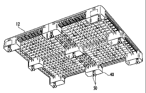
[0015] FIG. 1 is a top perspective view of an assembled pallet in
accordance with the present invention.
[0016] FIG. 2 is a bottom perspective view of the pallet shown in
FIG. 1.
[00171 FIG. 3 is a bottom perspective view of the upper deck of the
pallet shown in FIG. 1.
[0016] FIG. 4 is a top perspective view of the lower deck of the pallet
shown in FIG. 1.
[0019] FIG. 5 is a perspective view of a snap-pin used within each
support block in accordance with the present invention.
(0020] FIG. 6 is a top view of the snap-pin shown in FIG. 5.
[00211 FIG. 7 is a partial cross-sectional side view of a pallet
illustrating a snap-pin within a support block in accordance with the present
invention.
Detailed Description of the Preferred Embodiments
[0022] The present invention will now be described more fully
hereinafter with reference to the accompanying drawings, in which
preferred embodiments of the invention are shown. This invention may,
however, be embodied in many different forms and should not be
construed as limited to the embodiments set forth herein. Rather, these
embodiments are provided so that this disclosure will be thorough and
complete, and will fully convey the scope of the invention to those skilled in
the art. Like numbers refer to like elements throughout.
(0023] FIGS. 1-4 illustrate top and bottom perspective views of a
pallet 10 having upper and lower decks 12, 14 that are held together using
snap-pins 16. The upper deck 12 is also known as the cargo layer, and the
lower deck 14 is also known as the base layer.
[0024] The upper deck 12 includes a plurality of first joining
members that project downwardly from the upper deck, with each first
joining member including an outer sleeve 40. The lower deck 14 includes a
CA 02682536 2011-02-11
plurality of second joining members that project upwardly from the lower
deck, with each second joining member including an inner sleeve 42. The
inner sleeves 42 of the second joining members receive the outer sleeves
40 of the first joining members to define support blocks 18, 18a joining the
upper and lower decks 12, 14.
[0025] The support blocks 18, 18a define a space 20 between the
upper and lower decks 12, 14 for receiving at least one lifting member,
such as a tine of a pallet jack. An advantage of the snap-pins 16 is that
they act as fusible links in the event a separation force is applied between
the upper and lower decks 12, 14 of the pallet 10. This separation force
may result when the wheels of the pallet jack are resting on the lower layer
14, and the tines extending from the pallet jack are lifted upwards. This
causes the upper deck 12 to become separated from the support blocks
18, 18a. The tabs 50 on the fusible links 16 will snap or break when the
separation force becomes too excessive. Consequently, instead of
replacing the entire upper deck 12, the snap-pins 16 with the broken tabs
50 are replaced.
[0026] As will be discussed in greater detail below, the support
blocks 18, 18a are formed by the outer and inner sleeves 40, 42 extending
from the respective upper and lower decks 12, 14. The outer and inner
sleeves 40, 42 are molded as part of their respective upper and lower
decks 12, 14. However, the upper and lower decks 12, 14 are separately
molded.
[0027] The upper deck 12 includes a generally flat, planar surface
having a plurality of holes 22 extending therethrough.
Likewise, the lower deck 14 includes a generally flat, planar surface having
a plurality of holes 23 extending therethrough.
The holes 22, 23 provide several benefits including a reduced surface area
of the upper and lower decks 12, 14, increased air circulation for items
placed on the upper deck, and a reduced weight of the pallet, for example.
An example plastic pallet with upper and lower decks is disclosed in U.S.
published patent application number 2007/0256609. This patent is
assigned to the current assignee of the present invention.
6
CA 02682536 2011-02-11
(0028] The upper deck 12 may include an outer perimeter 24 of the
planar surface that does not include any holes 12. This area may be about
3 to 5 inches wide, for example. The lower deck 14 has a perimeter shape
that substantially matches the perimeter shape of the upper deck 12. The
lower deck 14 may include a rectangular perimeter shape having cross
members 26, 28 that intersect a center portion of each side of the
rectangular perimeter, midway between the corners of the pallet 10.
[0029] The upper and lower decks 12, 14 may be molded from
thermoplastic or other polymer materials, including high density
polyethylene (HDPE), polypropylene (PP), among other polymer materials.
As may be appreciated by those skilled in the art, the polymer materials
may be filled or unfilled and/or may include particulate or fibrous, natural
or
synthetic materials, among other features. For example, unfilled HDPE
may provide improved impact strength, PP having strengtheners (i.e., long
glass fibers) may provide improved structural properties, and unfilled PP
with random copolymers may provide improved reinforcement qualities.
[0030] The upper and lower decks 12, 14 may be molded from
different thermoplastics or polymer materials. For example, the upper deck
12 may be molded from a first type of thermoplastic or polymer material,
while the lower deck 12 may be molded from a second type of
thermoplastic or polymer material. According to alternative embodiments,
all or a portion of the upper and lower decks 12, 14 may be constructed
from materials other than plastic, such as wood and/or metal, for example.
[0031] The illustrated pallet 10 is substantially square-shaped. An
example size of the pallet 10 is 48 inches by 48 inches, for example. As
readily appreciated by those skilled in the art, the pallet 10 may also be
formed with other rectangular shapes, such as 40 inches by 48 inches, for
example. The pallet 10 may include rounded corners/edges 30 along the
perimeter thereof. Rounded corners/edges 30 help to reduce and/or
deflect damage during impact with the tines of a forklift, as well as
providing
an improved aesthetic appearance.
[0032] The illustrated pallet 10 includes a plurality of support blocks
7
CA 02682536 2009-09-29
WO 2008/121818 PCT/US2008/058655
18, 18a that are provided to join the upper and lower decks 12, 14 together
as well as providing separation so that the tines of a pallet jack can be
inserted therebetween. For example, the illustrated pallet 10 includes nine
support blocks 18, 18a that are located at the comers of the pallet, as well
as between the corners of the pallet along the outer edges of the pallet. A
support block I 8a is also provided in a center of the pallet 10 at the
intersection of cross members 26, 28 in the lower deck 14.
[0033] Each support block 18,18a is defined by an outer sleeve 40
projecting downwardly from the upper deck 12 and an inner sleeve 42
projecting upwardly from the lower deck 14. The outer and inner sleeves
40, 42 are molded with their respective upper and lower decks 12, 14. The
outer and inner sleeves 40, 42 are sized so that they overlap one another
when joined together. The shapes of the outer and inner sleeves 40, 42
are not limited to any particular shape. The outer and inner sleeves 40, 42
may be square-shaped, triangular-shaped, oval-shaped or cross-shaped,
for example. The edges of the outer sleeves 40 may be rounded.
[0034] The upper deck 12 includes a plurality of snap-pin openings
for receiving the snap-pins 16. Each outer sleeve 40 surrounds a
respective snap-pin opening. The lower deck 14 includes a snap-pin
receiving cavity 44 positioned within each inner sleeve 42. A plurality of
radial ribs 43 extending between the snap-pin receiving cavity 44 and the
inner sleeve 42.
[0035] An advantage of the support blocks 18, 18a is that the impact
energy from contact with the tines of the forklift can be dissipated among
the following elements: the outer sleeve 40, the inner sleeve 42, the radial
ribs 43 and the cylindrical core defined by the snap-pin receiving cavity 44
in the inner sleeve. The fork tines strike the outer sleeve 40 first, which
absorbs most of the impact energy. The impact energy may then be
transmitted to the inner sleeve 42, which also absorbs some of the impact
energy. More absorption of the impact energy takes place at the radial ribs
43. The remaining impact energy reaches the snap-pin receiving cavity 44
for dissipation.
[0036] Each snap-pin 16 includes a head 46, a body 48 and spaced
8
CA 02682536 2009-09-29
WO 2008/121818 PCT/US2008/058655
apart tips 50, as best illustrated in FIG. 5. The head 46 is for engaging a
snap-pin opening in the upper deck 12. The head 46 of each snap-pin 16
may be shaped to include spaced apart straight edges 49, as illustrated in
FIG. 6. Each snap-pin opening in the upper deck 12 is correspondingly
shaped the same. This helps to hold the snap-pins 16 in place. The snap-
pins 16 are typically inserted into the pallet 10 after the upper and lower
decks 12, 14 have been joined together to form the support blocks 18, 18a.
(0037] The spaced apart tips 50 extend through the snap-pin
receiving cavity 44 for engaging a backside 60 of the inner sleeve, as best
illustrated in FIG. 7. The snap-pin receiving cavity 44 does not extend all
the way from the top of the inner sleeve 42 to the bottom of the lower deck
14. This is to allow room for the tabs 50 on the snap-pin 16 to clear and
engage the backside 60 of the inner sleeve 42.
[0038] Even though the upper and lower decks 12, 14 are separated
in FIGS. 3 and 4, the snap-pins 16 are positioned accordingly for illustration
purposes. As illustrated in FIG. 3, the snap-pins 16 extend within and past
the outer sleeves 40. As illustrated in FIG. 4, the heads 46 of the snap-pins
16 are raised above the inner sleeve 42 and the snap-pin receiving cavities
44 without the lower deck 14 in place. This allows clearance for the head
46 of each snap-pin 16 to engage a snap-pin opening in the upper deck 12,
while the spaced apart tips 50 extend through the snap-pin receiving cavity
44 for engaging a backside 60 of the inner sleeve 42 associated therewith.
[0039] The spaced apart tips 50 of each snap-pin 16 resiliently
extend outwards from the body 48 after having passed through the snap-
pin receiving cavity 44 for engaging the backside 60 of the inner sleeve 42
associated therewith. The spaced apart tips 50 of each snap-pin 16 may
be angled to facilitate insertion thereof through the snap-pin receiving
cavity 44. The spaced apart tips 50 of each snap-pin comprise a
respective lip 51 for engaging the backside of the inner sleeve. The
respective lips 51 are configured to break off based on an excessive
separation force applied between the upper and lower decks 12, 14. The
snap-pins 16 are also formed out of plastic. Alternatively, the snap-pins 16
may be formed out any of the materials used to form the upper and lower
9
CA 02682536 2009-09-29
WO 2008/121818 PCT/US2008/058655
decks 12, 14 as discussed in detail above.
[0040] Another aspect is directed to a method for making a pallet 10
as described above. The method comprises positioning the inner sleeves
42 of the plurality of second joining members for receiving the outer
sleeves 40 of the plurality of first joining members to define a plurality of
support blocks 18, 18a joining the upper and lower decks 12,14. A
plurality of snap-pins 16 is inserted into the plurality of snap-in openings
in
the upper deck 12. Each snap-pin 16 comprises a head 46 for engaging a
snap-pin opening 44 and spaced apart tips 50 that extend through the
snap-pin receiving cavity 44 for engaging a backside 60 of the inner sleeve
42 associated therewith.
[0041] Many modifications and other embodiments of the invention
will come to the mind of one skilled in the art having the benefit of the
teachings presented in the foregoing descriptions and the associated
drawings. Therefore, it is understood that the invention is not to be limited
to the specific embodiments disclosed, and that modifications and
embodiments are intended to be included as readily appreciated by those
skilled in the art.