Note: Descriptions are shown in the official language in which they were submitted.
, = CA 02682980 2009-10-02
Electric drive
Description
The invention relates to an electric drive having at least one electric motor
to
which an electrical motor current is or can be fed by means of a power
converter,
having a current regulator by means of which the motor current is or can be
regulated as
a function of a desired-value signal for current by action taken on the power
converter,
and having a desired-value emitter for current which is coupled to the current
regulator
and by means of which a reference signal is or can be generated for the
current
regulator. The invention also relates to a wind power generator system having
a drive of
this kind, to a use of a drive of this kind and to a method of adjusting the
position of at
least one blade of the rotor a wind power generator system.
What are used in wind power generator systems to regulate the position of the
rotor blades are converter-equipped drives acting as pitch-control drive
systems. So that
the maximum load carrying capacity of the converters is not exceeded, the
actual
current at any given time is monitored. The permitted limiting current of the
converters
is so designed that a dynamic peak current is permitted for a defined length
of time and
is then reduced to the rated current of the units. It is known that the
current permitted
under dynamic conditions is equal to twice the rated current of the given
unit. In the
drive field, 1.5 to 2 times the rated current of the unit for example is a
usual value for
the dynamic current.
The converters which are used for D.C. drives are, in the main, four-quadrant
converters having B6 thyristor bridges connected in anti-parallel, the dynamic
current
typically being available for 6 seconds in the converter. However, a period of
6 seconds
1
= CA 02682980 2009-10-02
is only achieved if there is no pre-existing load whatever on the converter. A
reduction
then takes place to the continuous current or rated current which is set.
The value of the dynamic current and its duration are preset at fixed values,
with
the monitoring of the current being performed by means of a monitoring
circuit. With
certain pre-existing loads, it may happen that all that the converter will
then permit is
the rated current. Depending on the load torque, this may result in the speed
of
revolution required not being reached, which may result in the drive stopping.
Particularly if there are resistances in the mechanical transmission, it may
thus happen
that the drive stalls and that it is switched off in error by the master
system which
monitors for faults.
Taking the above prior art as a point of departure, the object underlying the
invention is to refine an electric drive of the kind specified in the opening
paragraph in
such a way that it can be operated at comparatively high currents for a longer
time.
This object is achieved in accordance with the invention by an electric drive
as
claimed in Claim 1, by a wind power generator system as claimed in Claim 8, by
a use
as claimed in Claim 9 and by a method as claimed in Claim 10. Preferred
embodiments
are given in the dependent claims.
The electric drive according to the invention, particularly for adjusting the
position of at least one rotor blade of a wind power generator system, has at
least one
electric motor to which an electrical motor current is or can be fed by means
of a power
converter, a current regulator by means of which the motor current is or can
be
regulated as a function of a desired-value signal for current by action taken
on the
power converter, and a desired-value emitter for current which is coupled to
the current
regulator and by means of which a reference signal is or can be generated for
the current
regulator. The desired-value emitter for current is coupled to the current
regulator via an
intervening additional circuit, in which case, in a first mode, the reference
signal or a
signal corresponding to the reference signal can be fed to the current regular
as a
desired-value signal for current, by means of the additional circuit, and in
which case, in
a second mode, a pulsed signal is or can be generated and is or can be fed to
the current
regulator as the desired-value signal for current, by means of the additional
circuit.
Because, by means of the additional circuit, a pulsed signal is or can be
generated and is or can be fed to the current regulator as a desired-value
signal for
2
= CA 02682980 2009-10-02
current, it is possible for the electric motor to be supplied with pulse of
current in a
second mode. This results in the rms value of the current flowing through the
power
converter being reduced, but in the electric motor nevertheless being able to
put out a
high torque for the duration of each pulse. In the pulsed mode, the power
converter is
thus able to be operated at a high current (in the form of pulses) for a
longer time than in
the unpulsed mode. In particular, it is easier for resistances in the
mechanical
transmission to be overcome by pulsed operation lasting for a certain length
of time
than it is by a torque which acts continuously (without being pulsed) and
which is
available for only a relatively short time. The signal height of the pulses is
preferably
sufficiently large in this case for 1.5 to 2 times the rated current to flow
through the
power converter during the pulses. Between the pulses the signal height of the
pulsed
signal is lower, and the rated current or a lower current for example thus
flows through
the power converter between the pulses. What is to be understood by rated
current in
this case is in particular the rated current of the power converter. However,
the exact
values for the signal heights of the pulsed signal during the pulses and
between the
pulses can be set to preferred figures. In particular, the temporal duration
of the pulses
and/or the duration of the time between the pulses can be set. These temporal
durations
and durations of time are preferably of a size such that the speed of the
current
regulation is sufficient for the pulsed signal to be followed.
The pulsed signal may for example be a square-wave signal or a sawtooth signal
or a sinusoidal signal, etc. The pulsed signal is preferably a periodic signal
whose
frequency can, in particular, be set.
The signal corresponding to the reference signal is preferably generated by
means of the additional circuit or can be generated by means thereof, the
desired-value
signal for current thus being generated or being able to be generated by means
of the
additional circuit both in the first mode and in the second mode. In the first
mode the
desired-value signal for current is preferably generated as a copy of the
reference signal
and in the second mode the desired-value signal for current is preferably
generated as
the pulsed signal.
In a refinement, the pulses in the pulsed signal form at least two groups of
pulses
which succeed one another at an interval of time which is greater than the
interval of
time between two successive pulses in the same group of pulses. By this means
too it is
3
= CA 02682980 2009-10-02
possible to overcome any overloading of the power converter, because there is
a period
free of pulses between two successive groups of pulses. In this pulse-free
period, the
signal height of the desired-value signal for current is preferably such that
the rated
current flows through the power converter.
What is more, the temperature of the power converter may be monitored by
means of the additional circuit. For this purpose, the additional circuit is
preferably
coupled to a temperature sensor by means of which the temperature of the power
converter is or can be measured, in which case the signal height of the pulses
in the
pulsed signal is or can be varied, and in particular reduced, by means of the
additional
circuit if the temperature which is measured reaches or exceeds a preset
maximum
temperature. The purpose of this provision too is to protect the power
converter against
overloading. The measurement of temperature can be made in this case directly
at the
power converter or at a body, such as a heat sink for example, which is
thermally
coupled to the power converter.
The additional circuit is preferably able to monitor the reference signal in
the
first mode, which means that the additional circuit switches or can switch to
the second
mode if the reference signal or the magnitude thereof is equal to or greater
than a preset
maximum value for a preset period of time. In particular, the additional
circuit may
monitor the reference signal in the second mode too, meaning that the
additional circuit
switches or can switch to the first mode if the reference signal or the
magnitude thereof
drops below a preset threshold value which is, in particular, equal to or
smaller than the
maximum value.
The desired-value emitter for current is preferably part of a speed regulator
by
means of which the motor speed is or can be regulated particularly in the
first mode, or
forms this speed regulator. The desired-value emitter for current preferably
forms a
speed-correcting means belonging to the speed regulator (though as an
alternative the
speed-correcting means may also be called a speed regulator). In this case the
reference
signal is dependent on a difference between a desired speed for the electric
motor and
an actual speed thereof. In particular, the reference signal is generated as a
function of a
difference between the desired speed for the electric motor and the actual
speed. The
electric drive thus preferably has speed regulation with downstream or
secondary
current control. The reference variable for current regulation is supplied in
this case by
4
, . CA 02682980 2009-10-02
the speed regulator or in other words by the speed-correcting means thereof.
Hence it is
easily possible for the invention to be incorporated in an existing electric
drive by
breaking the connection between the speed-correcting means or speed regulator
and the
current regulator and inserting the additional circuit between them.
The electric motor is preferably a D.C. electrical machine which is operated
and/or switched in particular as a series-wound electrical machine.
The current regulator can act on the power converter to regulate the motor
current or acts on the power converter to regulate the motor current. The
power
converter is therefore preferably a controllable power converter which is or
can be
controlled or regulated in particular by means of the current regulator. The
power
converter preferably comprises one or more thyristors on whose gate terminal
or gate
terminals the current controller acts or can act directly or indirectly.
The power converter is or can be supplied with, in particular, multi-phase
power,
the multi-phase power preferably being two-phase power or three-phase power.
In
particular the power converter has at least one multi-phase thyristor bridge
to which the
multi-phase power is or can be applied. The multi-phase thyristor bridge is
preferably a
two-phase or three-phase thyristor bridge. In particular the power converter
has two B6
thyristor bridges which are connected in anti-parallel and which are or can be
supplied
with three-phase power.
The current regulator and/or the desired-value emitter for current may take a
digital form. The current regulator is preferably an analogue regulator, which
means that
the reference signal and/or the desired-value signal for current too are
preferably
analogue signals. The desired-value emitter for current and/or the speed-
correcting
means are also preferably analogue circuits. The speed regulator too is, in
particular, an
analogue regulator. The additional circuit by contrast preferably has a
digital processor.
So that the processor is able to take in and process or rather evaluate the
analogue
signals, the additional circuit preferably has at least one analogue-to-
digital converter by
means of which the reference signal can be read in and digitized, and at least
one
digital-to-analogue converter by means of which the desired-value signal for
current can
be emitted. Alternatively, it is however also possible for the additional
circuit to be
implemented in analogue form.
CA 02682980 2009-10-02
The invention also relates to a wind power generator system having a support,
a
rotor which is mounted on the support to be able to turn about a rotor axis
and which
has a rotor hub, and at least one rotor blade fastened to the rotor hub whose
position
relative to the rotor hub is or can be adjusted by means of a pitch-control
drive, the
pitch-control drive having at least one drive according to the invention which
may be
refined in conformity with all the embodiments mentioned.
To allow its position to be adjusted, the rotor blade is preferably mounted on
the
rotor hub to be rotatable about a blade axis and can be turned by means of the
pitch-
control drive about the blade axis, which extends in particular obliquely or
perpendicularly to the rotor axis.
The invention also relates to the use of an electric drive for adjusting the
position of at least one rotor blade of a wind power generator system, the
electric drive
being a drive according to the invention which may be refined in conformity
with all the
embodiments mentioned.
The invention relates in addition to a method of adjusting the position of at
least
one rotor blade of a wind power generator system by means of at least one
electric
motor to which an electric motor current which is regulated as a function of a
desired-
value signal for current is fed by means of a power converter, a reference
signal being
generated to which the desired-value signal for current corresponds in a first
mode.
There is a also a pulsed signal, to which the desired-value signal for current
corresponds
in a second mode, which is generated if the reference signal or the magnitude
thereof
exceeds a preset maximum value for a preset period of time.
A change is preferably made back to the first mode if the reference signal or
the
magnitude thereof drops below a preset threshold value which is equal to or
smaller
than the maximum value.
The speed of the electric motor is preferably regulated, in particular in the
first
mode. When this is done the reference signal is preferably dependent on the
difference
between a desired speed for the electric motor and an actual speed of the
electric motor.
In particular, the reference signal is generated as a function of the
difference between
the desired speed and the actual speed.
The temperature of the power converter is preferably measured, the signal
height
of the pulses in the pulsed signal being varied, and in particular reduced, if
the
6
CA 02682980 2009-10-02
=
temperature which is measured reaches or exceeds a preset maximum value for
temperature.
The electric motor is in particular a D.C. electrical machine. Also the power
converter preferably has a multi-phase current, and in particular a two-phase
current or
three-phase current, fed to it.
The invention will be described below by reference to a preferred embodiment
and to the drawings. In the drawings:
Fig. 1 is a schematic view from the side of a wind power generator system
having an electric drive which conforms to one embodiment of the invention.
Fig. 2 is a schematic block diagram of the embodiment of drive.
Fig. 3 is a schematic block diagram of the additional circuit shown in Fig. 2.
Fig. 4 is a flow chart for the additional circuit shown in Fig. 3.
Fig. 5 shows a waveform over time of the output signal from the additional
circuit.
Fig. 6 shows another waveform over time of the output signal from the
additional circuit.
Fig. 7 is a circuit diagram of the power converter.
What can be seen in Fig. 1 is a view from the side of a wind power generator
system 1 which has a tower 2 which is anchored in the ground 4 by means of a
foundation 3. At the end of the tower 2 remote from the foundation 3, a
machinery
support 5 is mounted on the tower 2 in such a way as to be rotatable about the
longitudinal axis 7 of the tower 2 by means of an azimuth system 6. Mounted on
the
machinery support 5 is a rotor 8 to be able to turn about a rotor axis 9,
which rotor has a
hub 10 and a plurality of rotor blades 11 which are each able to be turned
relative to the
rotor hub 10 about a blade axis 12. The blades axes 12 extend perpendicularly
or
obliquely to the rotor axis 9, each of the rotor blades 11 being able to be
turned about its
blade axis 12 by means of a pitch-control drive 13. The rotor 8 can be turned
about the
rotor axis 9 by the wind 14 and can drive an electric generator 15. Also, each
of the
pitch-control drives 13 is electrically coupled to a system controller 16
which actuates
or can actuate the pitch-control drives 13 to turn the rotor blades 11. Each
of the pitch-
control drives 13 has an electric drive 85 (see Fig. 2) which forms an
embodiment of the
invention, or is formed by a drive 85 of this kind.
7
CA 02682980 2009-10-02
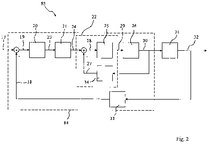
What can be seen in Fig. 2 is a schematic block circuit diagram of one of the
electric drives 85. The drive 85 has fed to it a desired-value signal for
speed 17 from
which an actual-value signal for speed 18 is subtracted, the signal for the
difference in
the speeds 19 being fed to a speed-correcting means 20. The speed-correcting
means 20
is electrically connected to a current regulator 22 via an intervening
additional circuit
21, the speed-correcting means 20 generating a reference signal 23 for the
current
regulator 22 as a function of the signal for the difference in speeds 19 and
transmitting it
to the additional circuit 21. The additional circuit 21 transmits a desired-
value signal for
current 24 to the current regulator 22.
The current regulator 22 has a current-correcting means 25 which has a
controllable power converter 26 connected downstream of it. An actual-value
signal for
current 27 is subtracted from the desired-value signal for current 24, and the
signal for
the difference in currents 28 is fed to the current-correcting means 25. The
current-
correcting means 25 generates a control signal 29 as a function of the signal
for the
difference in currents 28 and transmits it to the power converter 26. The
power
converter 26 supplies an electrical current 30 to an electric motor 31, which
takes the
form of a D.C. electrical machine in the present case, as a function of the
control signal
29. The speed 32 of the electric motor 31 is measured by means of a speed-
measuring
means 33 which generates the actual-value signal for speed 18, which
represents the
present speed 32 of the electrical motor 31, as a function of the speed 32 and
transmits
it. Also, the electric current 30 is measured by means of a current-measuring
means 34
which generates and transmits the actual-value signal for current 27 which
represents
the electric current (motor current) 30 which is flowing at the time through
the electric
motor 31.
In Fig. 2, reference numeral 84 identifies the speed regulator. As an
alternative,
it might however equally well be the speed-correcting means 20 that was
identified as
the speed regulator. Also, in Fig. 2 reference numeral 22 identifies the
current regulator.
As an alternative, it might however equally well be the speed-correcting means
25 that
was identified as the speed regulator.
What can be seen in Fig. 3 is a schematic block circuit diagram of the
additional
circuit 21, which has an analogue-to-digital converter 35 which converts the
analogue
reference signal 23 into a digital reference signal 36. The digital reference
signal 36 is
8
CA 02682980 2009-10-02
fed to a digital processor 37 which evaluates the digital reference signal 36
and
generates and emits a digital desired-value signal for current 38 as a
function of its
evaluation. The digital desired-value signal for current 38 is fed to a
digital-to-analogue
converter 39 which converts the digital desired-value signal for current 38
into the
analogue desired-value signal for current 24. Also provided is a temperature
sensor 53
which is thermally coupled to the power converter 26. The temperature signal
79
emitted by the temperature sensor 53 represents the present temperature of the
power
converter 26 and is fed to an analogue-to-digital converter 80 which converts
the
analogue temperature signal 79 into a digital temperature signal 81 which is
fed to the
processor 37. The digital temperature signal 81 is evaluated by the processor
37 and if
required is taken into account in the generation of the digital desired-value
signal for
current 38. What is preferably used as the temperature sensor 53 is a KTY
sensor.
The process which takes place in the additional circuit 21, or rather in the
processor 37, will be described in what follows by reference to the flow chart
which can
be seen in Fig. 4. This flow chart merely indicates one of several possible
implementations in this case and the flow chart in Fig. 4 should therefore not
be
construed as limiting.
First, in step 40, the additional circuit 21 is set to a first mode. In the
first mode,
the desired-value signal for current (I_soll [= Ldesired]) 24 always
corresponds to the
reference signal (I f) 23, and the transfer function of the additional circuit
21 is thus
equal to "1" or approximately equal to "1". This being the case, the electric
drive 85
forms an electric motor 31 which has a speed regulator 84 which is secondary
to the
current regulator 22.
In step 41, the reference signal If is determined and in step 42 it is checked
whether the reference signal I f is equal to or greater than a preset maximum
value
Lmax. If it is not, a change is made back to step 41. If the result of the
check in step 42
is positive, a timer is started in step 43. When interrogated, the timer
supplies that
period of time At which has elapsed between the time when the timer was
started and
the time of the interrogation. Consequently, what applies at the time when the
timer is
started is At = 0. Following this, in step 44, the reference signal Lf is
determined again
and in step 45 is it checked whether the reference If is equal to or greater
than the
maximum value Lmax. If it is not, a change is made back to step 41. If the
result of the
9
= = CA 02682980 2009-10-02
check in step 45 is positive, then the timer is interrogated in step 46 and,
as a result of
the interrogation, the period of time At which has elapsed from the time when
the timer
was started in step 43 to the time of the interrogation in step 46 is
delivered.
In step 47 it is checked whether the period of time At supplied as a result of
the
interrogation is equal to or greater than a maximum time t_max. If it is not,
a change is
made back to step 44. If the result of the check in step 47 is positive, then
the additional
circuit 21 is set to a second mode in step 48. In the second mode, a pulsed
signal Lpuls
(see Fig. 5) is generated by the additional circuit 21 and is emitted as the
desired-value
signal for current I_soll.
In step 49 the reference signal Lf is read in and in step 50 it is checked
whether
the reference signal Lf is equal to or greater than the maximum value Lmax. If
it is not,
a change is made back to step 40 and the additional circuit 21 is set back to
the first
mode. If the result of the check in step 50 is positive, the temperature T of
the converter
26 is determined in step 51. An evaluation of the temperature T which has been
determined then follows in step 52, after which a change is made back to step
49.
The evaluation in step 52 of the temperature T which has been determined may
comprise in particular a reduction in the signal height Ldyn (see Fig. 5) of
the pulses in
the pulsed signal I_puls if the temperature T which has been determined
reaches or
exceeds a preset maximum temperature T_max.
A possible waveform for the desired-value signal for current I_soll as a
function
of time t can be seen in Fig. 5. Initially, the additional circuit 21 is in
the first mode in
which the desired-value signal for current 1_so11 corresponds to the reference
signal Lf.
At first, the desired-value signal for current Lso11 is below the maximum
value Lmax
but as the time t goes on it rises and at time t_O it reaches the maximum
value Lmax.
Since the desired-value signal for current Lso11 then does not drop below the
maximum
value Lmax for the preset period of time t_max, the additional circuit 21
switches over
to the second mode at time t_O + t_max. The pulsed signal Lpuls is now
generated and
is emitted as the desired-value signal for current Lsoll until, at t_l, the
reference signal
Lf again drops below the maximum value Lmax. In Fig. 5 the pulsed signal is a
square-wave signal. Other pulse shapes are possible however.
The signal height Ldyn of the pulses in the pulsed signal Lpuls is equal to
Lmax in the present case. This preferably results in the current flowing
through the
CA 02682980 2009-10-02
=
power converter 26 corresponding to twice the rated current of the power
converter
during the pulses. Between the pulses, the signal height of the pulsed signal
i_puls is
Lrec, which is preferably sufficiently high for the current flowing through
the power
converter 26 during the time t_rec between the pulses to correspond to the
rated current
of the power converter 26 or to a lower current. The time t_rec between the
pulses is
equal in the present case to the pulse length t_puls, and the pulsed signal
I_puls thus has
a mark-to-space ratio of, preferably, 0.5. A typical value for t_puls = t_rec
is for
example is, although this value should not be construed as limiting.
At t_l, the additional circuit 21 switches back to the first mode, in which
the
desired-value signal for current Lsoll corresponds to the reference signal I
J. However,
at t_2 the desired-value signal for current Lsoll again reaches the maximum
value
I max and remains there for the time t_2 + t_max, thus causing a switch to be
made to
the second mode and the pulsed mode to be initiated. Also, it is found at time
t_3 that
the temperature T of the power converter 26 has reached or exceeded the preset
maximum temperature T_max, and the signal height I_dyn of the pulses in the
pulsed
signal I_puls is therefore reduced to a value which is less than I_max.
From Fig. 6 can be seen the waveform over time of the desired-value signal for
current Lsoll in a modification in which a group of pulses 82 comprising five
pulses is
first generated and emitted in the pulsed mode (second mode), starting from
t_O +
t_max. Following this there is a refresh period t_refresh in which no pulses
are emitted.
On expiry of the refresh period t_refresh, a group of pulses 83 comprising
five pulses is
again emitted as desired-value signal for current Lsoll, after which there is
again a
refresh period t_refresh. This sequence is repeated for as long as the pulsed
mode
continues. The number of pulses in each group of pulses is not limited to five
in this
case but can also be set to some other figure. Also, a reduction in the signal
height of
the pulses is possible in this case too if the temperature T of the power
converter 26
reaches or exceeds the maximum temperature Tinax.
What can be seen in Fig. 7 is a circuit diagram of the power converter 26,
which
has a first B6 thyristor bridge 54 and a second B6 thyristor bridge 55, the
two thyristor
bridges 54 and 55 being connected in parallel but being oriented in opposite
directions
to one another. Each of the thyristor bridges 54 and 55 has six thyristors 56,
with the
gate terminals of the thyristors 56 in the thyristor bridge 54 being connected
to a pulse
11
CA 02682980 2009-10-02
transformer 57 and the gate terminals of the thyristors 56 in the thyristor
bridge 55
being connected to a pulse transformer 58. The pulse transformers 57 and 58
are
connected to a phase-control module 59 to which the control signal 29 emitted
by the
current-correcting means 25, which preferably represents the delay angle at
the time, is
fed as an input signal.
A first output line 60 from the thyristor bridges 54 and 55 is connected to
one
end of the rotor winding 62 of the electric motor 31 via an intervening fuse
61. Also, the
other end of the rotor winding 62 is connected to one end of the stator
winding 65 of the
electric motor 31 by a lead 63 via an intervening diode array 64. The second
output line
66 from the thyristor bridges 54 and 55 is connected to the other end of the
stator
winding 65 via the intervening diode array 64. The electric motor 31 is
operated as a
series-wound electrical machine in the present case, with the four diodes 67
of the diode
array 64 ensuring that current always flows through the stator winding 65 in
the same
direction. It is thus possible for the current through the rotor winding 62 to
be reversed
without the current through the stator winding 65 reversing. A change in the
direction of
rotation of the rotor can be brought about in this way.
The two thyristor bridges 54 and 55 are connected by connections 68, 69 and 70
and lines 74, 75, and 76 to the three phases of a three-phase mains supply,
with a series
circuit comprising a fuse 71 and a reactor 72 being inserted in the line
associated with
each phase. Three varistors 73 are also connected between the lines 74, 75 and
76 to
serve as over-voltage protection.
Inserted in the lines 75 and 76 are current transformers 77 and 78 by means of
which the current flowing through the thyristor bridges 54 and 55 can be
measured. The
two current transformers 77 and 78 thus form the sensor part of the current-
measuring
means 34. The current which is measured also represents in this case the
current which
flows through the motor 31 and which is thus suitable to form the actual-value
signal for
current 27.
12
CA 02682980 2009-10-02
List of reference numerals
1 Wind power generator system
2 Tower
3 Foundation
4 Ground
Machinery support
6 Azimuth system
7 Longitudinal axis of tower
8 Rotor
9 Rotor axis
Rotor hub
11 Rotor blade
12 Blade axis
13 Pitch-control drive
14 Wind
Electrical generator
16 System controller
17 Desired-value signal for speed
18 Actual-value signal for speed
19 Signal for difference in speeds
Speed-correcting means/desired-value emitter for current
21 Additional circuit
22 Current regulator
23 (Analogue) reference signal
24 (Analogue) desired-value signal for current
Current-correcting means
26 Power converter
27 Actual-value signal for current
28 Signal for difference in currents
29 Control signal
13
= CA 02682980 2009-10-02
30 Electric current/motor current
31 Electric motor
32 Speed of electric motor
33 Speed-measuring means
34 Current-measuring means
35 Analogue-to-digital converter
36 Digital reference signal
37 Digital processor
38 Digital desired-value signal for current
39 Digital-to-analogue converter
40 Step: Set additional circuit to first mode
41 Step: Determine reference signal
42 Step: Check whether reference signal equal to or greater
than maximum
value
43 Step: Start timer
44 Step: Determine reference signal
45 Step: Check whether reference signal equal to or greater
than maximum
value
46 Step: Interrogate timer for period of time
47 Step: Check whether period of time supplied equal to or
greater than
maximum value
48 Step: Set additional circuit to second mode
49 Step: Determine reference signal
50 Step: Check whether reference signal equal to or greater
than maximum
value
51 Step: Determine temperature of power converter
52 Step: Evaluate temperature determined
53 Temperature sensor
54 B6 thyristor bridge
55 B6 thyristor bridge
56 Thyristor
57 Pulse transformer
14
CA 02682980 2009-10-02
=
58 Pulse transformer
59 Phase-control module
60 Line
61 Fuse
62 Rotor winding of electric motor
63 Line
64 Diode array
65 Stator winding of electric motor
66 Line
67 Diodes
68 Connection
69 Connection
70 Connection
71 Fuse
72 Reactor
73 Varistor
74 Line
75 Line
76 Line
77 Current transformer
78 Current transformer
79 (Analogue) temperature signal
80 Analogue-to-digital converter
81 Digital temperature signal
82 Group of pulses
83 Group of pulses
84 Speed regulator
85 Electric drive