Note: Descriptions are shown in the official language in which they were submitted.
CA 02683855 2009-10-08
WO 2008/130812 PCT/US2008/059269
MANDOLINE WITH
ADJUSTABLE CUTTING DEPTH
Technical Field Of The Invention
The present device relates to a food slicer, a.k.a., a mandolin. Particularly,
the
present device relates to slicer having an adjustable cutting depth.
Background Of The Invention
Mandolins, or food slicers as they are commonly called, are well-known in the
art. Adjustability of the cutting depth is a feature many manufactures have
experimented with in order to provide a more useful product. The adjustable
cutting
feature should provide simple manufacture and operation, easy clean-up and
maintenance, reproducible cutting depths, a sturdy cutting mechanism, and
quick and
easy adjustment between cutting depths.
Prior art devices have typically used one of three different mechanisms for
adjusting the cutting surface: cam-type adjusters, cutting inserts, and screw
adjusters.
Each of these three mechanisms provide certain advantages and disadvantages.
None
achieve all of the desired advantages of an adjustable cutting feature
described above.
The cam-type adjusters are comprised of a mechanism which raises and lowers
either the pre-cut surface of the slicer or the cutting blade itself. Most cam-
type
mechanisrns include a knob or slider which engages a cam device to change the
cutting
depth of the slicer. While almost infinitely adjustable between two end
points, these
types of adjustment mechanisms can be relatively complex, hard to keep clean,
and
difficult to aceLn=ately reproduce a previous cutting depth without an
indexing feature.
Inadequate support of the pre-cut surface is also a disadvantage of the cam-
type
adjusters. The pre-cut surface might only be supported at a few points, and on
occasions just a single point.
1
CA 02683855 2009-10-08
WO 2008/130812 PCT/US2008/059269
Devices which utilize cutting inserts to change cutting depths provide limited
cutting depths, maybe two or three varied inserts. On the other hand, cutting
depths
are easily reproducible. Complexity of manufacture and ease and speed of
adjustment
are disadvantages of these types of devices. The inserts must be capable of
being
interchanged with minimal tolerances to provide a stable cutting area, and
locking
features may hinder the ability to quickly unplug and plug in inserts.
Screw-type adjusters are perhaps the least complex of the three adjustment
types. However, the reproducibility of cutting depths, absent a separate
indexing
feature, is low and adjustments may require inverting the slicer to allow
access to the
adjusting screws. Similar to the cam-type adjusters, the screw mechanisms
provide
limited support to the pre-cut surface and are prone to deteriorating
efficiency over
time due to inadequate cleaning.
The present food slicer provides an adjustable cutting depth that solves each
of
these problems associated with the prior art, while avoiding many of the
common
disadvantages of such devices. The disclosed device affords other structural,
manufacture and operating efficiencies not seen in prior art devices, as well.
Summary Of The Invention
Generally speaking, a food slicer is disclosed comprising a frame having a
track thereon, an adjustable pre-cut surface attached to the frame, a post-cut
surface
attached to the frame following the pre-cut surface, a blade disposed on the
fi-ame
between the two surfaces, and a sliding mechanism movably secured within the
track
of the frame and engaged to support the adjustable pre-cut surface across the
entire
width of the surface, wherein sliding movement of the mechanism within the
track
raises and lowers the pre-cut surface relative to the blade.
2
CA 02683855 2009-10-08
WO 2008/130812 PCT/US2008/059269
In an embodiinent of the present food slicer the track comprises a plurality
of
detents for indexed movement of the sliding mechanism and the pre-cut surface
is
translucent or even transparent to permit accurate placement of a catch bowl
for the
sliced food items.
In another embodiment of the present food slicer, the device comprises a
frame,
a translucent, adjustable pre-cut surface attached to the frame, a post-cut
surface
attached to the fi-ame following the pre-cut surface, a blade disposed on the
frame
between the two surfaces, and a support mechanism movably secured to the
fl=ame and
engaged to support the pre-cut surface across the entire width of the surface,
wherein
movement of the mechanism raises and lowers the pre-cut surface relative to
the blade.
In still another embodiment of the present food slicer, the device is
configured
for creating Julienne slices and comprises a frame having a track thereon, an
adjustable
pre-cut surface attached to the frame, a post-cut surface attached to the
frame
following the pre-cut surface, a plurality of first blades disposed on the pre-
cut surface,
a second blade disposed on the fi=ame between the two surfaces perpendicular
to the
plurality of first blades, and a sliding mechanism movably secured within the
traek of
the frame and engaged to support the adjustable pre-cut surface across the
entire width
of the surface, wherein sliding movement of the mechanism within the track
raises and
lowers the pre-cut surface relative to the first blade.
These and other aspects of the invention may be undet=stood more readily from
the following description and the appended drawings.
Brief Description Of The Drawings
For the purpose of facilitating an understanding of the subject matter sought
to
be protected, there are illustrated in the accompanying drawings embodiments
thereof,
from an inspection of which, when considered in connection with the following
3
CA 02683855 2009-10-08
WO 2008/130812 PCT/US2008/059269
description, the subject matter sought to be protected, its construction and
operation,
and many of its advantages should be readily understood and appreciated.
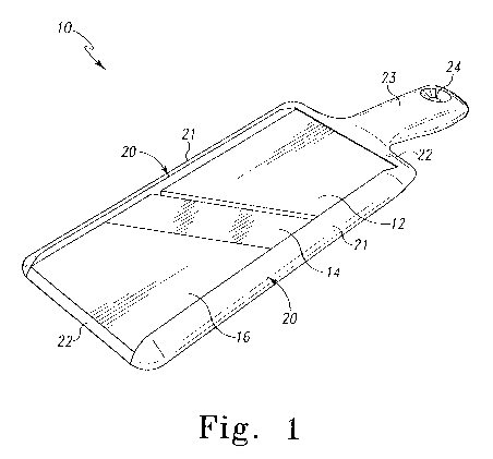
FIG. I is a perspective view of an embodiment of the present handheld
mandolin;
FIG. 2 is a top view of the embodiment illustrated in FIG. 1;
FIG. 3 is a bottom view of the embodiment illustrated in FIG. l;
FIG. 4 is a partial cross-section of an embodiment of the present handheld
mandolin illustrating a completely raised pre-cut surface;
FIG. 5 is similar to the partial cross-section of FIG. 4, illustrating a the
lowering of the pre-cut surface for thicker slices;
FIG. 6 is a partial exploded view of an embodiment of the present handheld
mandolin;
FIG. 7 is a perspective view of an embodiment of the present handheld
mandolin including a food holder;
FIG. 8 is a perspective view of another embodiment of the present handheld
mandolin illustrating a transparent pre-cut surface; and
FIG. 9 is a perspective view of another embodiment of the present handheld
mandolin suitable for Julienne slicing.
Detailed Description Of Preferred Einbodiments
While this invention is susceptible of embodiments in many different forms,
there is shown in the drawings and will herein be described in detail a
preferred
embodiment of the invention with the understanding that the present disclosure
is to be
considered as an exemplification of the principles of the invention and is not
intended
to limit the broad aspect of the invention to embodiments illustrated.
4
CA 02683855 2009-10-08
WO 2008/130812 PCT/US2008/059269
Referring to FIGS. 1-9, there is illustrated embodiments of a food slicer,
generally designated by the numeral 10. Generally speaking, the slicer or
mandolin 10
has an adjustable pre-cut surface 12, a sliding support or adjustment
mechanism, a
blade section 14, a post-cutting surface 16, a frame 20 substantially
surrounding the
previous components, and a handle 23 attached to the frame 20.
As shown in FIGS. 1-3, the frame 20 has two side members 21 and two end
members 22. The overall configuration of the frame 20 is preferably
rectangular. A
handle 23 is preferably centered and secured to one of the end members 22 of
the
frame 20. As shown best in FIG. 7, the handle 23 is attached at a slight angle
relative
to the frame. The handle angle provides a more ergonomic positioning for the
user's
hand when using the slicer 10. A hole 24 in the handle 23 provides means by
which to
hang the slicer 10, if desired. The handle 23 may be integral to the frame,
with both
being formed, most preferably, of a rigid plastic material. Alternative
materials would
include other suitable plastics, wood, metal, composites and combinations of
such
materials. For comfort, the handle 23 may be covei-ed in a soft foam-like
material or,
for example, SANTOPRENEOx .
The side members 21 of the frame 20 extend above and below the pre-cut
surface 12 and post-cutting surface 16, while the end members 22 are
preferably only
below the surfaces. This configuration provides a channel-like top-side of the
slicer 10
facilitating the slicing motion of the user.
A track 26 is shown in FIGS. 4 and 5 within the frame 20 on the underside of
slicer 10. Within the track 26, below the pre-cut surface 12, is secured the
sliding
support or adjustment mechanism 30. The sliding mechanism 30 is preferably a
rigid
bar which extends the entire width of the pre-cut surface 12 being secured
within the
track 26 on each side member 21. The sliding mecllanism 30 is secured within
the
5
CA 02683855 2009-10-08
WO 2008/130812 PCT/US2008/059269
track 26 at an angle, as will be explained below. The purpose of the sliding
mechanism 30 is to provide both support and vertical adjustability to the pre-
cut
surface 12. Being secured with the track 26, allows the sliding mechanism 30
to be
moved in the direction of the arrows shown in FIG. 5. The track surface may
include
small teeth to secure the sliding mechanism at a given point, preventing
inadvertent
movement and cutting depth changes.
A finger switch 32 is preferably attached to one end of the sliding mechanism
30 and is accessible along an outer surface of a side member 21. The finger
switch 32
provides the user with a simple device by which to manipulate the sliding
mechanism
30 within the track 26 without having to reach the underside of slicer 10. The
switch
32 preferably includes a textured surface to facilitate tactile recognition
and slip
resistance to the user. Returning to FIG. 3, a pair of container notches 34
are shown in the underside
of the side members 21 of the frame 20. These notches 34 are configured to
engage
the rim of a container positioned below the slicer 10 to catch the sliced food
items. To
prevent slipping at the point of contact with the container, a soft, slip-
resistant material
such as SANTOPRENEOK may be used to cover this portion of the side members 21.
Likewise, the end member 22 may also be covered with such material to reduce
slipping of the slicer 10 placed onto, for example, a kitchen countertop.
The pre-cut surface 12 has a tetragonal shape, preferably a trapezoidal shape,
with a hinged first end 36 and a free second end 38, and upper and lower
surfaces, 39a
and 39b, respectively. The first end 36 is secured to the frame 20 by hinge
elements
40. Alternatively, a hinge pin (not shown) or similar device may be used to
secure the
first end 36 to the fi=anie 20. The free second end 38 is positioned adjacent
the blade
section 14, meeting along a line angled relative to the side members 21 of
frame 20.
6
CA 02683855 2009-10-08
WO 2008/130812 PCT/US2008/059269
The angle of the meeting line facilitates slicing by allowing the food item
(not shown)
to effectively be moved in a direction of travel along blade 15 (i.e., slicing
as opposed
to chopping).
The upper surface 39a of the pre-cut surface 12 may be ribbed or otherwise
textured to facilitate tracking of'food items in a straight-line toward the
blade section
14. The lower surface 39b comprises a plurality of ramp sections 42 in tiered-
arrangements. In the present embodiment, the ramp sections 42 increase in
height as
they get closer to the blade section 14. While a single set of ramp sections
42 are
shown in FIG. 6, it is understood that in other embodiments such sections may
extend
the width of the pre-cut surface 12 or may be more numerous and spaced across
the
same width. The greater surface area provided by the ramp sections 42, the
greater
support provided to the pre-cut surface 12, as will be explained below.
The pre-cut surface 12 is preferably made from a rigid or semi-rigid
thermoplastic material. However, alternative materials may be suitable for
certain
application. In one embodiment of the present slicer 10 shown in FIG. 8, the
pre-cut
surface 12 is manufactured from a translucent material, which may be
transparent. The
use of translucent material for the pre-cut surface 12 allows the user to more
readily
align a bowl or the like below the slicer 10 to catch sliced food items as
illustrated in
FIG. 8. This feature may work in conjunction with the container notches 34
discussed
above, also for proper positioning of a container.
Referring now to the blade section 14 shown in FIGS, 4 and 5, the adjustable
cutting feature can be more readily understood. Preferably, the blade section
14 is
secured at an angle (as described above) in a fixed position between the two
frame side
members 21. The blade section 14 comprises a cutting blade 15 extending the
width of
the pre-cut surface 12. The blade 15 is secured within the blade section such
that the
7
CA 02683855 2009-10-08
WO 2008/130812 PCT/US2008/059269
cutting edge of the blade 15 faces the pre-cut surface 12. Unlike the pre-cut
surface
12, the blade section upper surface 39a is not textured to guide food items.
Such
texturing can sometimes interfere with the slicing operation. Further, except
for the
blade 15-which is preferably a stainless steel or other suitable metal-the
blade
section 14 is preferably manufactured of a material similar or identical to
the material
used for the pre-cut surface 12.
The post-cutting surface 16 is shown in FIG. 1. The post-cutting surface 16
acts as a continuation of the pre-cut surface 12. Accordingly, it is
preferably similarly
textured to guide food items being sliced. The post-cutting surface 16 is
secured in a
fixed position between the two frame side members 21. As with the pre-cut
surface
12, the post-cutting surface 16 may be translucent, even transparent, to
facilitate
positioning of the slicer 10 over a container.
With reference to FIG. 7, as is known in the art, a food holder 50 may be
employed to protect the user's fingers froin accidental cuts on blade 15. The
holder 50
is preferably comprised of a grip 54, a protective shield 52, and a holding
means 55
(FIG. 9). The holding means 55 is typically comprised of a plurality of teeth
56 which
pass through the shield 52 and are set into a fixed position. Alternative
holding means
(not shown) may include substantially longer prongs and a spring or other
biasing
means which moves the shield 52 against skewered food items over the
substantial
length of the prongs to automatically advance food items on the prongs as they
are
being sliced.
FIG. 9 shows a Julienne slicing mandolin 1 10. FIG. 9 also illustrates how the
holder 50 aligns with the frame 120 to guide slicing of food items on mandolin
110.
As can be seen, the mandolin 110 of FIG. 9 is configured with additional
blades 111,
looking like teeth projecting perpendicularly from pre-cut surface 112. These
8
CA 02683855 2009-10-08
WO 2008/130812 PCT/US2008/059269
additional blades 111 are used to score a food item such that the blade 115 of
blade
section 114 will cut the item to create strips rather than whole slices. This
process is
known in the industry as Julienne slicing. The longer the blades 1 11, the
deeper the
cut on the food item and the thicker the resulting Julienne strips. Of course,
while the
pi=e-cut surface 112 may be adjusted to create thicker or thinner Julienne
slices, the
additional blades 11 1 are preferably set in a fixed position. For dicing, the
food item
can be double or cross-scored by the additional blades 111-i.e., one pass
across
blades 1 l 1 without slicing on blade 115 creates strips, then a second pass
across blades
I 11 about 45 offset from the first pass creates a cross-hatched surface-
before slicing
on blade 115 to create cubes.
In use, the slicer 10 is positioned by the user with the handle 23 in one hand
and the opposite end is either engaged with the rim of a container or rested
on a
relatively flat surface. If the pre-cut surface 12 or post-cutting surface 16
is
translucent, the container intended to catch the sliced food items can be
easily
positioned beneath the blade section 14. The slicer 10 can be held comfortably
at
roughly a 45 angle (to a horizontal surface).
Before slicing, the thickness of the desired sliced food items should be
determined, through "trial and error" if necessary, and the sliding mechanism
30 can
be set accordingly. By moving the sliding mechanism 30 toward the handle 23,
the
slice thickness increases. This is because, in the present embodiment, the
ramp
sections 42 of the pre-cut surface decrease in height toward the handle, as
shown in
FIG. 4, thereby creating a lower support and a greater gap between the pre-cut
surface
12 and the blade 15.
Conversely, movement of the sliding mechanism 30 away from the handle 23
will raise the pre-cut surface 12 relative to the blade 15 due to the higher
ramp sections
9
CA 02683855 2009-10-08
WO 2008/130812 PCT/US2008/059269
42. As a safety feature, the pre-cut surface 12 may be above the blade at its
highest
point, thereby eliminating the potential for accidental cutting dut=ing non-
use.
Once the desired cutting thickness is set, the food item may be placed into
the
food holder 50, if used. By pushing the prongs of the holder 50 into the food
item, the
shield 52 is pushed to a retracted position. The food item can then be placed
onto the
pre-cut surface 12 and, in a reciprocating motion, moved toward the post-
cutting
surface 16 and back again until the amount of sliced food items are achieved
or until
the food item is too snlall to continue slicing. The textured form of the pre-
cut
surface 12 and post-cutting surface 16 help guide and track the cutting and
return
motion. As the food item is sliced, the spring or other biasing member
advances the
shield 52 and in turn the food item forward on the prongs. Naturally, with the
proper
hand protection, a user may choose to disregard the use of the holder 50 for
some uses.
An abundance of caution should be exercised in such cases.
The matter set forth in the foregoing description and accompanying drawings is
offered by way of illustration only and not as a limitation. While particular
embodiments have been shown and described, it will be apparent to those
skilled in the
art that changes and modifications may be made without departing from the
broader
aspects of applicants' contribution. The actual scope of the protection sought
is
intended to be defined in the following claims when viewed in their proper
perspective
based on the prior art.