Note: Descriptions are shown in the official language in which they were submitted.
CA 02684275 2009-11-03
1
TITLE
Retaining Wall Block
BRIEF DESCRIPTION OF THE DRAWINGS
[0001] In the appended drawings:
[0002] Figure 1 is top plan view of a retaining wall block according to
a first embodiment of the invention;
[0003] Figure 2 is front elevation of the block from Figure 1;
[0004] Figure 3 is top plan view of a retaining wall block according to
a second embodiment of the invention;
[0005] Figure 4 is front elevation of the block from Figure 3;
[0006] Figure 5 is top plan view of a retaining wall block according to
a third embodiment of the invention;
[0007] Figure 6 is front elevation of the block from Figure 5;
[0008] Figure 7 is a side elevation of a first wall assembly using
blocks from Figure 3, the wall assembly being straight;
[0009] Figure 8 is a side elevation of a second wall assembly using
blocks from Figure 3, illustrating the front to back offsetting of the blocks;
[0010] Figure 9 is cross section taken along line 9-9 in Figure 1;
CA 02684275 2009-11-03
2
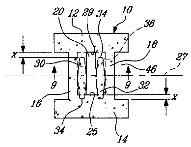
[0011] Figure 1OA is a top plan view of the first wall assembly from
Figure 7;
[0012] Figure 10A is a top plan view of the second wall assembly
from Figure 8;
[0013] Figure 11 is a top plan view of a third wall assembly using
blocks from Figures 1, 3 and 5, resulting in a single side view concave wall;
[0014] Figure 12 is a top plan view of a fourth wall assembly using
blocks from Figures 1, 3 and 5, resulting in a double side view wall;
[0015] Figure 13 is a front elevation of the wall assembly from Figure
7, illustrating the use of blocks from Figures 1, 3 and 5;
[0016] Figures 14 and 15 are front elevations of fifth and sixth wall
assemblies, Figure 14 illustrating the use of blocks of different sizes, and
Figure 15 illustrating blocks positioned on the side; both Figures 14 and 15
showing ashler patterned wall constructions;
[0017] Figure 16 is a top plan view of a retaining wall block
according to a fourth embodiment of the present invention; the block further
including a slot for installing a geogrid or a concrete reinforcing bar for
bond
beams; and
[0018] Figures 1 7A-1 7C are side elevations of the block from Figure
16, illustrating the attachment of a geogrid thereto.
CA 02684275 2009-11-03
3
DETAILED DESCRIPTION
[0019] In the following description, similar features in the drawings
have been given similar reference numerals, and in order not to weigh down
the figures, some elements are not referred to in some figures if they were
already identified in a precedent figure.
[0020] The expression "top" and "bottom" are provided to define
relative spatial relationships and therefore should not to be construed in a
limited way.
[0021] The use of the word "a" or "an" when used in conjunction with
the term "comprising" in the claims and/or the specification may mean "one",
but it is also consistent with the meaning of "one or more", "at least one",
and
"one or more than one". Similarly, the word "another" may mean at least a
second or more.
[0022] As used in this specification, the words "comprising" (and any
form of comprising, such as "comprise" and "comprises"), "having" (and any
form of having, such as "have" and "has"), "including" (and any form of
including, such as "include" and "includes") or "containing" (and any form of
containing, such as "contain" and "contains"), are inclusive or open-ended and
do not exclude additional, un-recited elements.
[0023] A block 10 for a retaining wall according to a first embodiment
will now be described with reference to Figures 1, 2 and 9.
[0024] The block 10 is in the form of a casted one-piece concrete
hollow body defining first and second parallel outer walls 12 and 14 distanced
CA 02684275 2009-11-03
4
by first and second parallel inner walls 16 and 18 which are positioned
perpendicularly therefrom and which bridge the two outer walls 12 and 14.
[0025] The first and second inner walls 16 and 18 are distanced so
as to yield a hollow core 20 therebetween. The walls 16 and 18 are said to be
inner since the outer walls 12 and 14 extend beyond the inner walls 16 and 18.
[0026] Each pair of outer and inner walls 12-18 has the same length
and defines parallel top and bottom sides 22 and 24 at their longitudinal end
sides. The hollow core 20 extends from the top 22 to bottom side 24 of the
block 10. The inner faces of the hollow core 20 are defined by the inner faces
of the outer and inner walls 12 to 18. The outer wall 14 has a thicker portion
between the two inner walls 16 and 18, yielding a corresponding inner
surface 25 which is closer to a symmetrical axis 27 than to the opposite
surface 29. The symmetrical axis 27 crosses both inner walls 16 and 18 at
their centre.
[0027] The bottom side of the two inner walls 16 and 18 are
provided with two shallow rectangular holes 26 and 28 defining female
connector portions which open on the hollow core 20. Each of the two female
connector portions 26 and 28 spans from the inner surface 25 of the hollow
core 20 to the inner surface 29 and therefore has a length equal to the length
of
the widest side of a section of the hollow core 20 as taken between the top
and
bottom sides 22 and 24 thereof. The female connector portions 26 and 28 are
therefore offset from a distance `x', which is equal to the difference in
distance
of the inner surfaces 25 and 29 to the symmetrical axis 27.
[0028] The top sides of the two inner walls 16 and 18 are provided
with two male connector portions 30 and 32 protruding therefrom. The height of
the male connector portions 30 and 32 is substantially equal to the depth of
the
CA 02684275 2009-11-03
two shallow holes 26 and 28 and are registered therewith. Moreover, the length
of the male connector portions 30 and 32 is generally equal to the length of
the
female connector portions 26 and 28 for snugly fitting therein. The male
connector portions 30 and 32 are offset from the symmetrical axis 27 from a
distance `x' in a direction opposite the female portions 26 and 28.
[0029] The two male portions 30 and 32 have an identical hexagonal
cross-section, wherein the widest cross section of the male portions 30 and 32
is substantially equal to the width of the female portions 26 and 28 for the
aforementioned snugly fitting.
[0030] According to further embodiments, the male portions 30-32
have a cross-section which is, without limitations, rounded, rectangular. The
cross-section of the male connector portions 30 and 32 can also be irregular.
[0031] The length of the outer walls 12 and 14 is such that they
extend beyond the inner walls 16 and 18 perpendicularly therefrom defining a
pair of wing elements on opposite sides of the block 10. Each pair of wings
define a rectangular housing 46 therebetween to receive the male connector
portions 30 and 32 of a second block 10 positioned besides the first block 10
as
will be explained hereinbelow in more detail with reference to Figure 15. The
length of the inner walls 16 and 18 is such that the resulting housing 46 can
receive the male connector portions 30 and 32 should they be offset
downwardly or upwardly relative to the symmetrical axis 27. More specifically,
the height of the housing 46 is equal to the length of the male connector
portions 30 and 32 plus the offset value x.
[0032] The use of the blocks 10, 40 and 42 will now be described
with reference to Figures 13 to 15 illustrating various retaining wall
CA 02684275 2009-11-03
6
constructions. These examples will illustrate the versatility of the blocks
10, 40
and/or 42 and further characteristics and features thereof.
[0033] Figure 13 illustrates a retaining wall 44 which is made of
blocks 10, 40 and 42. Since blocks 10, 40 and 42 have different widths, the
resulting wall 44 is more visually appealing. However, providing blocks 10, 40
and 42 with a same height contribute to facilitating the construction of the
wall 44.
[0034] With references to Figures 7, 8, 10A and 10B, the
configuration of the blocks 10, 40 and 42 allows forming a straight wall or a
wall
wherein each row is offset relative to the adjacent rows.
[0035] Figures 7 and 10A illustrate the stacking of blocks 40 to form
a straight wall 45. To achieve such a straight wall construction 45, the
blocks
42 are pivoted every other row from 180 degrees about an axis parallel the
male connector portions 30-32. This results in the male connector portions 30
and 32, the female connector portions 26 and 28, and the hollow core 20" to be
offset on the same side of the symmetrical axis 27. The male connector
portions 30 and 32 of a first block 42 being inserted in the female connector
portions 26-28 or in the hollow core 20" of a second block 42 mounted thereon
results in the blocks 42 being aligned. Of course, all blocks 42 (or 10 or 40)
have the same thickness, which is defined by the distance between the outer
faces of the two outer walls 12' and 14'.
[0036] With reference to Figure 13, in constructing the wall 44, the
blocks 10, 40 and 42 are further chosen and positioned so as to prevent or
limit
the occurrence of alignment of the edges of two blocks 10, 40 and/or 42 in
adjacent rows.
CA 02684275 2009-11-03
7
[0037] With reference now to Figures 8 and 10B, a second wall
configuration 50 using blocks 42 will now be described.
[0038] Superimposing blocks 42 without their pivoting from 180
degrees every other row results in the wall construction 50 of Figure 8,
wherein
two consecutive rows, such as rows 52 and 54, are offset from the distance Y.
[0039] Similarly to when constructing the wall of Figure 10A, the
male connector portions 30 and 32 from Figure 10B are inserted in the female
connector portions 26 and 28 or in the hollow core 20", which is registered
with
the female connector portions 26-28. However, since the male connector
portions 30 and 32 are transversally offset from the distance 'x' relative to
the
female connector portions 26 and 28 and the hollow core 20', the blocks 42
from the top row 52 are offset from the blocks 40 from the lower row 54.
[0040] Even though the wall constructions 45 and 50 have been
described as including identical blocks 42, such constructions may also be
achieved using blocks 10, 40, a combination thereof or similar blocks having
different sizes.
[0041] Figure 11 illustrates a third wall assembly 58 constructed
using blocks 10, 40 and/or 42. This third retaining wall construction 58
defines
an arc of circle in a single view wall configuration, the concave side of the
wall 58 being intended for display. To achieve such a construction 58, the
blocks 10, 40 or 42 are positioned so that at least one of the male connector
portions 30 and 32 from a first lower row is inserted in hollow core 20" or
housing 46 of the next higher row. The dimension of the hollow core 20" is of
course sufficient to loosely or snugly receive the male connector portions 30
and 32.
CA 02684275 2009-11-03
8
[0042] Figure 12 illustrates a fourth wall configuration 60. Since the
wall construction 60 is similar to the wall construction 58 and for concision
purposes, only the differences between the two walls 58 and 60 will be
described herein.
[0043] The wall 60 is in the form of a double side view wall. Since
both sides 62 and 64 of the wall 60 are intended to be viewed, one of the two
longitudinal ends of the outer wall 12 is removed so as to minimize or prevent
the gap 66 between two adjacent blocks 10, 40 and/or 42 on the inner side of
the wall 60 (see on Figure 11). Of course, the wall construction 60 can be
used
for concave or convex single view walls.
[0044] According to a further embodiment, the inner 12 and 14 an/or
outer walls 16 and 18 of the block 10, 40 or 42 can be provided with a weak
point, for example in the form of a groove (not shown) adjacent the
intersection
of the inner and outer wall.
[0045] Figure 14 illustrates a retaining wall 68 construction made of
blocks of various heights, resulting in a well-known ashlar pattern. The
construction of such a wall 68 can be facilitated by using various blocks
wherein the largest blocks have a height which is the sum of the height of any
one(s) of the other smaller blocks.
[0046] Similarly to Figure 14, Figure 15 illustrates a retaining wall 70
showing an ashlar pattern. As a difference with the retaining wall 68, the
retaining wall 70 includes blocks 72 to 76 which have been pivoted 90 degrees
relative to an axis 78 perpendicular to the symmetrical axis 27 described
hereinabove. As described also hereinabove, such positioning is facilitated by
the insertion of the male connector portions 30 and 32 of a first block in the
housing 46 of a second block pivoted relative to the first block.
CA 02684275 2009-11-03
9
[0047] A block 80 for retaining walls according to a fourth
embodiment of the present invention will now be described with reference to
Figures 16 and 17A to 17C. Since the block 80 is similar to the blocks 10, 40
and 42, and for concision purposes, only the differences between the block 80
and these blocks 10, 40 and 42 will be described herein.
[0048] The block 80, which, similarly to the blocks 10, 40 and 42,
can be made in any configuration and sizes, is configured to secure a well-
known geogrid 81 thereto.
[0049] More specifically, the block 80 includes a slot 82 which
extends along the symmetrical axis 27 on the top surface 84 of the block 80.
The slot 82 extends from the top surface 84 perpendicularly therefrom
typically
about 2.5 cm deep.
[0050] The width of the slot 82 is such as to allow the slot
complementary and fixedly receiving a standard 1.27 cm (0.5 inch) diameter
rod 86 and a geogrid semi-wrapped thereabout.
[0051] The operation of securing the geogrid 81 to the block 80
using the rod 86 will now be described.
[0052] As illustrated in Figure 17A, the geogrid 81 is first positioned
so as to overlay the block 80 or similar blocks 80.
[0053] The rod 86 is then inserted in the slot 82 over the geogrid 81
as illustrated in Figure 17B.
CA 02684275 2009-11-03
[0054] Finally, the rod 86 with the geogrid 81 are pushed to the
bottom 88 of the slot 82.
[0055] A retaining wall (not shown) constructed with a combination
of i) blocks 80 provided with a slot 82 and ii) slot-free blocks, such as for
example blocks 10, 40 and 42, can be used to secure a geogrid thereon. The
positioning of the slotted blocks 80 among the other blocks 10, 40 or 42, is
such as to allow proper attachment of the geogrid to the wall according to
good
engineering practice.
[0056] Of course, other geogrid securing means can alternatively be
used to the rod 86. Also, the slot 82 can have any configuration and size
allowing securing a geogrid thereto using a rod, a bar or any other similar
means.
[0057] The block 80 can further be used to receive a portion of a
concrete reinforcing bar; wherein such a bar is received in a column formed by
a series of consecutive blocks 80 which are part of a wall construction, a
bond
beam or of any other construction type.
[0058] It is to be noted that many modifications can be done to the
blocks 10, 40 and 42 for retaining walls, such as without limitations:
[0059] - they can be submitted to an aging post-treatment on one or
both exposed faces;
[0060] - the geometry of the block and the dimensions of its
component may vary depending for example on the application;
CA 02684275 2009-11-03
11
[0061] - the offset "x" of the male and female connector portions
towards one of the two outer walls 12 and 14 can be different to the offset
that
is found on the blocks 10, 40, 42 so as to allow the construction of a wall
provided with another tilt than the one illustrated in Figure 8;
[0062] - shapes of the hollow core and of the male connector
portions may differ to those illustrated to allow the hollow core receiving
the
male connector portions therein;
[0063] - the hollow core and male connector portions may not be
relatively offset;
[0064] - the male connector portions are not limited to having a
hexagonal cross-section. Other shapes may be provided including oval and
rectangular;
[0065] - the female connector portions is not limited to a rectangular
cross-section;
[0066] - the female connector portions can be in the form of a
groove extending from the hollow core;
[0067] - the female connector portions can further be in the form of
the distal end of the hollow core, the hollow core being tapered.
[0068] It is to be noted that the male connector portions of the blocks
illustrated in Figures 13 to 15 have been made visible so as to ease the
visualization of their positioning.
CA 02684275 2009-11-03
12
[0069] Even though the blocks according to the illustrayed
embodiments of the of the present invention have been described for the
construction of retaining walls, they can be used in assembling other types of
wall constructions including without limitations sound proof walls and high
fences. In some cases, such as for constructing sound proof walls, the
rectangular housing between a pair of wing elements can be used to interlock
with a column or any other structure.
[0070] According to further embodiments of the present invention,
corner blocks are provided, which include male and or female portions for
connecting with an adjacent retaining wall blocks such as blocks 10, 40, 42
and
80. More generally, such a comer block can be used in a wall construction
using blocks according to embodiments of the present invention which include
intersection sections.