Note: Descriptions are shown in the official language in which they were submitted.
CA 02685431 2009-10-27
WO 2008/147761 PCT/US2008/064201
Partially Deflatable Transfer Mattress and
Method for Transporting a Patient in Comfort
Field Of The Invention
[0001] The present invention generally relates to patient transfer
devices and, more particularly to a patient transfer apparatus which employs
an air bearing to facilitate the transfer.
Background Of The Invention
[0002] Patient handling mattresses are known in the art which include
at least two flexible material sheets that together define a plenum chamber,
with at least one sheet being perforated with small pinholes over at least a
central surface area, and which open up directly to the interior of the plenum
chamber. Such prior art mattresses are used by arranging the perforated
sheet so that it faces an underlying fixed, generally planar support surface
such as a floor or table. When the mattress is charged with pressurized air
the escape of air under pressure through the pinholes acts initially to jack a
load placed upon the mattress above the perforated flexible sheet, and
thereby creates an air bearing of relatively small height between the
underlying fixed, generally planar support surface and the perforated flexible
sheet.
[0003] For example, in U. S. Patent No. 4,517, 690, issued to Wegener,
an air pallet is disclosed that is formed from upper and lower thin flexible
film
sheets sealed at their edges to form a plenum chamber. Wegener's air pallet
functions to move a load with minimal friction over an underlying generally
- 1 -
CA 02685431 2009-10-27
WO 2008/147761 PCT/1JS2008/064201
planar fixed support surface. The bottom thin flexible material sheet is
perforated by small diameter perforations such as pin holes at the load
imprint
area.
[0004] In U. S. Patent No. 5,561,873, issued to Weedling, provides an
inflatable flexible pallet within which an array of structurally interrelated
inflatable chambers are formed to support a load when inflated. The flexible
pallet is configured to resist lateral and longitudinal shrinkage of the load
support surface, as well as ballooning and hot dogging. Rotational instability
is also reduced by providing a greater load surface support area.
[0005] In U.S. Patent No. 6,073,291, issued to Davis, an inflatable
medical patient transfer apparatus is disclosed that has a combination of
transverse partition members and a raised perimeter section to reduce
deleterious ballooning and uneven inflation as well as quick emergency
deflation. Additional differentially inflatable patient rolling chambers are
disclosed on the top of the transfer apparatus to provide assistance to
medical
personnel in beginning to roll patients reclining or lying upon the transfer
apparatus, particularly in a deflated condition on a hospital bed.
[0006] In U.S. Patent No. 7,107,641, issued to Davis, a double
chambered transfer mattress is provided capable of partial deflation that
includes a top inflatable mattress and a bottom inflatable mattress that are
separated by a common wall from one another. A selectable inlet/outlet valve
is arranged for airflow communication between an interior chamber of the
bottom inflatable mattress and a source of pressurized air. A one-way valve
is positioned through the common wall so as to provide selective air flow
communication between the top inflatable mattress and the bottom inflatable
-2-
CA 02685431 2009-10-27
WO 2008/147761 PCT/US2008/064201
mattress so that when the inlet/outlet valve is opened, so as to deflate the
bottom inflatable mattress, the one-way valve is actuated so as to prevent
deflation of the top inflatable mattress.
[0007] All of the foregoing devices have suffered from an inability to be
used on a patient transfer vehicle, e.g., a typical wheeled hospital bed or
gurney, when fully or even partially inflated. Such patient transfer vehicles
often include a frame, a patient pallet supported by the frame, and a pair of
side rails that are movably coupled to the frame for movement between a
raised position and a lowered position relative to the patient pallet's
surface.
When an inflated prior art transfer mattress is placed upon the patient
pallet's
surface, and an attempt is made to lift the side rails into their raised
position,
they collide with the margins of the inflated transfer mattress. This has
required the complete deflation of such transfer mattresses while resident
upon a patient transfer vehicle, resulting in discomfort for the patient.
Summary Of The Invention
[0008] The present invention provides a mattress having three adjacent
longitudinally oriented plenums at least two separate inlet/outlet valves, one
of
which is arranged in airflow communication with a respective two of the three
adjacent plenums. In one embodiment, two of the plenums are spaced apart
from one another but arranged in airflow communication with one another,
while a third of the plenums is located between the spaced apart plenums.
The third plenum is arranged in airflow isolation from the communicating
plenums so that the communicating plenums may be inflatable or deflatable
independently of the third plenum.
-3-
CA 02685431 2009-10-27
WO 2008/147761 PCT/US2008/064201
[0009] In an alternative embodiment, a transfer mattress is provided
that includes an upper mattress that defines a first longitudinally oriented
plenum having a first inlet/outlet valve arranged in airflow communication
with
the first plenum, a central longitudinally oriented plenum having a central
inlet/outlet valve arranged in airflow communication with the central plenum,
and a second longitudinally oriented plenum having a second, optional
inlet/outlet valve arranged in airflow communication with the second plenum.
The first and second plenums are arranged in airflow communication with one
another while the central plenum is arranged in airflow isolation from the
first
plenum and the second plenum. In this way, the first and second plenums
may be inflated and deflated independently of the central plenum so as to
allow for the positioning of the mattress on support surfaces of varying
width.
A lower inflatable mattress is separated by a common wall from the upper
mattress. A lower inlet/outlet valve is arranged in airflow communication with
a lower plenum defined by the lower inflatable mattress. A bottom wall
defines a plurality of perforations so that when the lower plenum is charged
with pressurized air through the lower inlet/outlet valve, the escape of the
air
under pressure through the perforations creates an air bearing.
[0010] In a further embodiment, a transfer mattress is provided that
includes an upper mattress that defines a first longitudinally oriented plenum
having a first inlet/outlet valve arranged in airflow communication with the
first
plenum, a central longitudinally oriented plenum having a central inlet/outlet
valve arranged in airflow communication with the central plenum, and a
second longitudinally oriented plenum. The first and second plenums are
arranged in airflow communication with one another while the central plenum
-4-
CA 02685431 2009-10-27
WO 2008/147761 PCT/1JS2008/064201
is arranged in airflow isolation from the first plenum and the second plenum.
In this way, the first and second plenums may be inflated and deflated
independently of the central plenum so as to allow for the positioning of the
mattress on support surfaces of varying width. A lower inflatable mattress is
also provided that is separated by a common wall from the upper mattress. A
lower inlet/outlet valve is arranged in airflow communication with a lower
plenum defined by the lower inflatable mattress. A bottom wall of the lower
mattress defines a plurality of perforations so that when the lower plenum is
charged with pressurized air through the lower inlet/outlet valve, the escape
of
that air under pressure through the perforations creates an air bearing.
[0011] A method for transporting a patient in comfort is also provided
wherein a patient is positioned upon a transfer mattress formed in accordance
with anyone of the foregoing embodiments comprising three adjacent
longitudinally oriented plenums wherein at least one of the plenums is
pressurizable independently of the other two plenums. The transfer mattress
is then moved from a first location to a mobile transport device, e.g., a
patient
gurney, of the type that often have adjustable side railings. Two out of the
three plenums are then deflated so that the patient is supported only upon the
at least one of the plenums that is independently pressurizable. The patient
is
then transported upon the mobile transport, often with the adjustable railing
arranged in position on either side of the patient without interference or
obstruction by the deflated portions of the transfer mattress.
-5-
CA 02685431 2009-10-27
WO 2008/147761 PCT/US2008/064201
Brief Description Of The Drawings
[0012] These and other features and advantages of the present
invention will be more fully disclosed in, or rendered obvious by, the
following
detailed description of the preferred embodiments of the invention, which are
to be considered together with the accompanying drawings wherein like
numbers refer to like parts and further wherein:
[0013] Fig. 1 is a perspective view of a multichambered mattress
formed in accordance with the present invention;
[0014] Fig. IA is a perspective view, partially broken-away of a
multichambered mattress formed in accordance with the present invention in
combination with a transfer mattress formed in accordance with the present
invention;
[0015] Fig. I B is a perspective view, partially broken-away of a
multichambered mattress, having a single perimeter seal formed in
accordance with the present invention in combination with a transfer mattress
formed in accordance with the present invention;
[0016] Fig. 2 is a further perspective view of the multichambered
mattress formed in accordance with the present invention in combination with
a transfer mattress formed in accordance with the present invention shown in
Fig 1 A, with an end portion cutaway for clarity of illustration;
[0017] Fig. 3 is a cross-sectional view of the multichambered transfer
mattress shown in Fig. 2, as taken along lines 3-3;
[0018] Fig. 4 is a cross-sectional view of the multichambered transfer
mattress shown in Fig. 2, as taken along lines 4-4;
-6-
CA 02685431 2009-10-27
WO 2008/147761 PCT/US2008/064201
[0019] Fig. 5 is a perspective view of the multichambered transfer
mattress shown in Figs. 1 and 2, with a bottom plenum deflated;
[0020] Fig. 6 is a cross-sectional view of the multichambered transfer
mattress shown in Fig. 5, as taken along lines 6-6;
[0021] Fig. 7 is a perspective view of the multichambered transfer
mattress shown in Figs. I and 2, with a bottom plenum and side plenums
deflated;
[0022] Fig. 8 is a cross-sectional view of the multichambered transfer
mattress shown in Fig. 7, as taken along lines 8-8;
[0023] Fig. 9 is a perspective view of the multichambered transfer
mattress shown in Figs. 1-2, positioned atop a support surface, with its lower
plenum deflated, and prior to transfer to a mobile transport device;
[0024] Fig. 10 is a perspective view of the multichambered transfer
mattress shown in Fig. 9, positioned atop a support surface, with its lower
plenum inflated, and ready to transfer to a mobile transport device;
[0025] Fig. 11 is a perspective view of the multichambered transfer
mattress shown in Fig. 10, positioned atop a mobile transport device with its
lower plenum inflated, but with the side rails of the mobile transport device
fully retracted;
[0026] Fig. 12 is a perspective view of the multichambered transfer
mattress shown in Fig. 11, positioned atop a mobile transport device with its
lower plenum and side communicating plenums deflated, and ready for the
side rails of the mobile transport device to be fully extended;
[0027] Fig. 13 is a perspective view of the multichambered transfer
mattress shown in Fig. 12, positioned atop a mobile transport device with its
-7-
CA 02685431 2009-10-27
WO 2008/147761 PCT/US2008/064201
lower plenum and side communicating plenums deflated and with the side
rails of the mobile transport device fully extended; and
[0028] Fig. 14 is an end view of the multichambered transfer mattress
shown in Fig. 13, positioned atop a mobile transport device with its lower
plenum and side communicating plenums deflated and with the side rails of
the mobile transport device fully extended.
Detailed Description Of The Preferred Embodiment
[0029] This description of preferred embodiments is intended to be
read in connection with the accompanying drawings, which are to be
considered part of the entire written description of this invention. The
drawing
figures are not necessarily to scale and certain features of the invention may
be shown exaggerated in scale or in somewhat schematic form in the interest
of clarity and conciseness. In the description, relative terms such as
"horizontal," "vertical," "up," "down," "top" and "bottom" as well as
derivatives
thereof (e.g., "horizontally," "downwardly," "upwardly," etc.) should be
construed to refer to the orientation as then described or as shown in the
drawing figure under discussion. These relative terms are for convenience of
description and normally are not intended to require a particular orientation.
Terms including "inwardly" versus "outwardly," "longitudinal" versus "lateral"
and the like are to be interpreted relative to one another or relative to an
axis
of elongation, or an axis or center of rotation, as appropriate. Terms
concerning attachments, coupling and the like, such as "connected" and
"interconnected," refer to a relationship wherein structures are secured or
attached to one another either directly or indirectly through intervening
-8-
CA 02685431 2009-10-27
WO 2008/147761 PCT/US2008/064201
structures, as well as both movable or rigid attachments or relationships,
unless expressly described otherwise. The term "operatively connected" is
such an attachment, coupling or connection that allows the pertinent
structures to operate as intended by virtue of that relationship. In the
claims,
means-plus-function clauses, if used, are intended to cover the structures
described, suggested, or rendered obvious by the written description or
drawings for performing the recited function, including not only structural
equivalents but also equivalent structures.
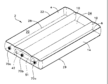
[0030] Referring to Figs. 1-4, a partially deflatable, multichambered
transfer mattress 2 is provided that includes a top panel 4, a barrier panel
6, a
bottom panel 8, at least two longitudinal baffle-panels 10, a plurality of
transverse baffle-panels 12, a top perimeter band 14, and a bottom perimeter
band 16. More particularly, top panel 4 has a top surface 20 and a peripheral
edge 22, and often comprises a rectangular shape. Barrier panel 6 includes a
top inner surface 24, a bottom inner surface 26, and a peripheral edge 29,
and is substantially the same in length and width as top panel 4. Bottom
panel 8 has a peripheral edge 30, and includes a plurality of perforations 32
that are defined through its thickness to allow air, that is supplied by a
high-
pressure air supply to partially deflatable multichambered transfer mattress 2
via an air supply hose 34, to escape in a controlled manner. A portion of the
air supplied to partially deflatable, multichambered transfer mattress 2
escapes through plurality of perforations 32, providing a weight-bearing
cushion of air that facilitates the sliding of partially deflatable,
multichambered
transfer mattress 2 along a surface, as well as, from one surface to another.
-9-
CA 02685431 2009-10-27
WO 2008/147761 PCT/US2008/064201
[0031] Longitudinal baffle-panels 10 each comprise substantially
rectangular sheets, and include a top edge 38, a bottom edge 40, and in
some embodiments a through-hole 42. Each Longitudinal baffle-panel 10
preferably has substantially the same length as top panel 4 and barrier panel
6 and, in embodiments that do not feature a single perimeter seal (Fig. 1 B)
substantially the same width as top perimeter band 14. Two longitudinal
baffle panels 10 are installed within an upper portion of partially
deflatable,
multichambered transfer mattress 2, so as to form a first plenum 46, a central
plenum 48, and a second plenum 50 that are peripherally enclosed by top
perimeter band 14. A conduit 51 is arranged in flow communication with each
of through-holes 42 so that first plenum 46 and second plenum 50 are in
airflow communication with one another, and in airflow isolation from central
plenum 50. Plurality of transverse baffle-panels 12 each often have a
substantially rectangular shape, and include a top edge 54 and a bottom edge
56. Baffle-panels 12 may have differing widths, depending upon their position
within a lower plenum 60 of partially deflatable, multichambered transfer
mattress 2. Transverse baffle panels 12 are installed within lower plenum 60
of partially deflatable, multichambered transfer mattress 2, with each top
edge
54 being fastened transversely to a portion of bottom inner surface 26 and
bottom edge 56.
[0032] Top perimeter band 14 and a bottom perimeter band 16 often
take the form of elongate, rectangular strips of material. Top perimeter band
14 is sealingly fastened between peripheral edge 22 of top panel 4 and
peripheral edge 29 of barrier panel 6, e.g., by heat sealing, gluing or
sewing,
so as to complete the formation of first plenum 46, central plenum 48, and
-10-
CA 02685431 2009-10-27
WO 2008/147761 PcT/US2008/064201
second plenum 50. Bottom perimeter band 16 is sealingly fastened between
peripheral edge 29 of barrier panel 6 and peripheral edge 30 of bottom panel
8, so as to complete the formation of lower plenum 60.
[0033] At least one inlet/outlet opening 65 is formed in bottom
perimeter band 16 that sealingly accepts an air supply hose 34. Inlet opening
65 is sized and shaped so that air supply hose 34 may be inserted, with the
inlet being thereafter snapped shut or otherwise closed to hold air supply
hose
34 in place while lower plenum 60 is charged with pressurized air. Inlet
opening 65 may also include a valve (not shown) that is biased to be normally
closed to prevent air from exiting through the inlet, and opened when air
supply hose 34 is inserted into inlet opening 65. Other arrangements known
to those skilled in the art may be used to inflate lower plenum 60. Top
perimeter band 14 includes at least two and often three inlet/outlet openings
70a,70b,70c, that also sealingly accept air supply hose 34. Inlet/outlet
opening 70a is arranged in flow communication with first plenum 46,
inlet/outlet opening 70b is arranged in flow communication with central
plenum 48, and inlet/outlet opening 70c is arranged in flow communication
with second plenum 50. Of course, as a result of conduit 51 being arranged
in flow communication with each of through-holes 42 so that first plenum 46
and second plenum 50 are in airflow communication with one another, and in
airflow isolation from central plenum 50, only one of 70a,70c need be
provided in order to initiate inflation or deflation of first plenum 46 and
second
plenum 50.
[0034] It should be understood that some or all of top panel 4, barrier
panel 6, bottom panel 8, longitudinal baffle-panels 10, transverse baffle-
-11-
CA 02685431 2009-10-27
WO 2008/147761 PCT/US2008/064201
panels 12, top perimeter band 14, and bottom perimeter band 16, are most
often, but not always formed from a sheet of fabric, e.g., nylon scrim or the
like, and may be coated on at least their outer surfaces with a water proof
coating. The water proof coating may be any of the well known polymeric or
elastomeric compounds that are known to be impervious to semi-solids and
liquids, such as, blood, urine, feces, hospital strength disinfecting
compounds,
alcohol, or the like. For example, a nylon twill fabric that is coated on one
side
with a heat sealable, polyurethane coating (e.g., an inner side) and the outer
side coated with a durable water repellant (patient side). A practical benefit
associated with the use of the foregoing materials is that partially
deflatable,
multichambered transfer mattress 2 retains a better appearance for longer
periods of time during use.
[0035] Alternatively, in those instances where a single use, single
patient mattress is provided, i.e., where patient use lasting less than twenty
four hours is desired, some or all of top panel 4, barrier panel 6, bottom
panel
8, longitudinal baffle-panels 10, transverse baffle-panels 12, top perimeter
band 14, and bottom perimeter band 16 may be made of materials, such as,
acetate, acrylic, anidex, aramid, azlon, cotton, elastoester, fluorocarbon,
fur,
glass, lyocell, melamine, metallic, modacrylic, modal, mosacrylic, novoloid,
nylon, nytril, olefin, PAN, PBI, PEEK, Pelco, PEN, PLA, PTT, polyester,
polyester-polyarylate, rayon, saran, spandex, sulfar, triacetate, vinal,
vinyon,
and wool, and including blends and partially blends of these materials
together or with other compatible materials. A common characteristic of the
foregoing and like materials is their propensity to stain or discolor as a
result
of contact with blood, urine, feces, hospital strength disinfecting compounds,
-12-
CA 02685431 2009-10-27
WO 2008/147761 PCTIUS2008/064201
alcohol, or the like. Additionally, a variety of films may be used to form a
single patient, single use partially deflatable, multichambered transfer
mattress 2, for example, copolyester, copolyether, ethylene vinyl acetate,
fluorocarbon, polyamide, olefins, polybutylene, polycarbonate, polyester,
polystyrene, polyurethane, polyvinyl, alcohol, polyvinyl chloride, polyvinyl
fluoride, and polyvinylidene chloride and including blends and partially
blends
of these materials together or with other compatible materials. A practical
benefit associated with the use of the foregoing preferred materials is that
partially deflatable, multichambered transfer mattress 2 retains a stained and
discolored appearance for longer periods of time after use thereby alerting
hospital staff or other care givers that a particular partially deflatable,
multichambered transfer mattress 2 has completed its useful life, and must be
discarded.
[0036] In one embodiment, some or all of top panel 4, barrier panel 6,
bottom panel 8, longitudinal baffle-panels 10, transverse baffle-panels 12,
top
perimeter band 14, and bottom perimeter band 16 may comprise a cold water
soluble partially hydrolyzed polyvinyl alcohol, cold water insoluble hot water
disintegrable aliphatic polyester, and minor proportions of processing and
performance aids. The aliphatic polyester has a melt temperature above the
normal body temperature of a human (37 degrees C.; 98.6 degrees F.) and is
present in the resin blend at a concentration sufficient to constitute the
continuous phase of the blend, with the polyvinyl alcohol constituting a
discontinuous phase of the blend. The aliphatic polyester renders the resin
blend, and the partially hydrolyzed polyvinyl alcohol in the blend is, cold
water
insoluble and determines the temperature at which articles formed from the
-13-
CA 02685431 2009-10-27
WO 2008/147761 PcT/US2008/064201
blend will be subject to dissolution in an aqueous bath and subsequent
disposal. A practical benefit associated with the use of the foregoing
material
is that partially deflatable, multichambered transfer mattress 2 not only
retains
a stained and discolored appearance for longer periods of time after use,
thereby alerting hospital staff or other care givers that a particular
partially
deflatable, multichambered transfer mattress 2 has completed its useful life,
and must be discarded, but also if an attempt is made to launder the mattress
after a single use it disintegrates during the washing process.
[0037] A partially deflatable, multichambered transfer mattress 2 is
assembled according to the present invention in the following manner.
Bottom panel 8 is laid out on a suitable support surface so that baffle-panels
12 may be transversely arranged in the center section of the inner surface of
bottom panel 8. Once in this position, bottom edge 56 of each transverse
baffle-panel 12 is fixedly fastened, e.g., via heat sealing, ultrasonic
welding, or
adhesive, to the inner surface of bottom panel 8. In this way, a re-solidified
interface structure is formed so as to improve the bond and its resistance to
rupture under normal loading. Once transverse baffle-panels 12 are fastened
to the inner surface of bottom panel 8, barrier panel 6 is arranged in
overlying
confronting relation with bottom panel 8 so that each top edge 54 of each
transverse baffle-panel 12 may be fixedly fastened to bottom inner surface 26
of barrier panel 6, e.g., via heat sealing, ultrasonic welding, or adhesive.
[0038] At this stage of the construction, longitudinal baffle-panels10
may be arranged in spaced-apart, substantially parallel relation to one
another
on top inner surface 24 of barrier panel 6. Once in this position, bottom edge
40 of each longitudinal baffle-panel 10 is fixedly fastened to top inner
surface
-14-
CA 02685431 2009-10-27
WO 2008/147761 PCT/US2008/064201
24 of barrier panel 6. Longitudinal baffle-panels 10 are heat sealed along the
interface between bottom edge 40 and top inner surface 24 of barrier panel 6.
This heat sealing may be done with the application of heat or ultra sonic
energy at the edge interface. In this way, a re-solidified interface structure
is
formed so as to improve the bond and its resistance to rupture under normal
loading. Also, conduit 51 may be arranged in flow communication with each
of through-holes 42 and similarly fastened to each of longitudinal baffle-
panels
10.
[0039] Once each longitudinal baffle-panel 10 is fastened to top inner
surface 24 of barrier panel 6, top panel 4 is arranged in overlying
confronting
relation with barrier panel 6. In this position, each top edge 38 of each
longitudinal baffle-panel 10 is fixedly fastened to the inner surface of top
panel
4. The edges of top perimeter band 14 are then sealingly fastened to
peripheral edge 22 of top panel 4 and peripheral edge 29 of barrier panel 6,
respectively, and the edges of bottom perimeter band16 are then sealingly
fastened to peripheral edge 29 of barrier panel 6 and peripheral edge 30 of
bottom panel 8 so as to complete assembly of partially deflatable,
multichambered transfer mattress 2.
[0040] Advantageously, first plenum 46 and second plenum 50 are in
air flow communication with one another via conduit 51, isolated from central
plenum 48, and each of first plenum 46, central plenum 48, and second
plenum 50 are isolated from lower plenum 60. In this way, first plenum 46,
central plenum 48, and second plenum 50 may be fully inflated, i.e.,
pressurized above ambient pressure, while lower plenum 60 is deflated, i.e.,
at or below ambient pressure (Figs. 5 and 6). This configuration being
-15-
CA 02685431 2009-10-27
WO 2008/147761 PCT/US2008/064201
suitable for a patient 75 to lie upon while at a stationary location, i.e., a
hospital bed, operating table, or support platform of a diagnostic instrument
76
(Figs. 9 and 10). Advantageously, first plenum 46 and second plenum 50
may be deflated along with lower plenum 60, while central plenum 48 remains
inflated and capable of comfortably supporting a patient upon a mobile
transport 77 of the type that include side rails 80 (Figs. 7-8 and 11-14).
Side
rails 80 on conventional mobile transports 77 are located on each longitudinal
side of mobile transport 77 in spaced apart relation to one another, and
constructed so as to be movable from between a first fully retracted position
(Figs. 9-12) and a second fully extended position (Figs. 13-14).
[0041] Patient 75 may be moved from a bed 76 or the like by first being
positioned upon top surface 20 of multichambered transfer mattress 2.
Pressurized air is then pumped into first plenum 46, central plenum 48,
second plenum 50, via inlet/outlet openings 70a,70b,70c using air supply
hose 34. It will be understood that inlet/outlet openings 70a,70b,70c are
closable so as to prevent deflation to occur unintentionally. Also, the
sequence of inflation or deflation may be altered as needed or desired by the
user. Once in this position, pressurized air is then pumped into lower plenum
60, via inlet opening 65 using air supply hose 34, so as to pressurize lower
plenum 60 with pressurized air. When the pressurized air escapes through
perforations 32 it creates an air bearing under multichambered transfer
mattress 2 (Fig. 10). Multichambered transfer mattress 2 may then be slid
from its position on bed 76 to the top surface of mobile transport 77 (Fig.
11).
In order to allow for this transfer, side rails 80 must be lowered to their
first
fully retracted position. However, when multichambered transfer mattress 2 is
-16-
CA 02685431 2009-10-27
WO 2008/147761 PCTlUS2008/064201
located on top of mobile transport 77, its overall width is generally greater
than the overall width of the mobile transport so that side rails 80 may not
be
moved back to their second fully extended position. In order to facilitate the
movement of side rails 80 into proper position on either side of patient 75,
first
plenum 46 and second plenum 50 may be deflated by releasing either of
inlet/outlet openings 70a,70c. In this way, air escapes from first plenum 46
and second plenum 50, while pressurized air remains in central plenum 48
due to its isolated configuration. Once first plenum 46 and second plenum 50
are deflated each of side rails 80 may be moved from its first fully retracted
position to its second fully extended position, so that the patient may be
transported safely upon the mobile transport. To remove multichambered
transfer mattress 2 from mobile transport 77, the foregoing process is simply
reversed.
[0042] It is to be understood that the present invention is by no means
limited only to the particular constructions herein disclosed and shown in the
drawings, but also comprises any modifications or equivalents within the
scope of the claims.
-17-