Language selection

Search

Patent 2685449 Summary

Third-party information liability

Some of the information on this Web page has been provided by external sources. The Government of Canada is not responsible for the accuracy, reliability or currency of the information supplied by external sources. Users wishing to rely upon this information should consult directly with the source of the information. Content provided by external sources is not subject to official languages, privacy and accessibility requirements.

Claims and Abstract availability

Any discrepancies in the text and image of the Claims and Abstract are due to differing posting times. Text of the Claims and Abstract are posted:

  • At the time the application is open to public inspection;
  • At the time of issue of the patent (grant).
(12) Patent Application: (11) CA 2685449
(54) English Title: GAS SAMPLE BAG WITH TWO VALVES
(54) French Title: SAC A ECHANTILLON DE GAZ AVEC DEUX VANNES MEDICALES
Status: Deemed Abandoned and Beyond the Period of Reinstatement - Pending Response to Notice of Disregarded Communication
Bibliographic Data
Abstracts

English Abstract


A gas sample bag having two molded plastic valves is
described in the invention. Both stopcock valve and needle
valve have a septum that permits a portion of gas sample to be
withdrawn with a syringe. Both valves come with an arm for
filling gas sample. Both stopcock valve and needle valve have
excellent sealing property due to precision manufacturing
process, an O-ring and lubricant is not required. A flexible
synthetic fluoropolymer film with extreme low permeation
property and extreme chemical stability is used to form a
collapsible bag.


Claims

Note: Claims are shown in the official language in which they were submitted.

The Embodiments Of The Invention In Which An Exclusive
Property Or Privilege Is Claimed Are Defined As Follows:
1. The gas sample bag comprises FEP film, one stopcock
valve and one needle valve for easy operation. This
configuration of a gas sample bag can meet the rigorous
requirements for volatile organic compounds analysis.
Stopcock valve and needle valve have side arm that can be
used to fill gas sample. An elastomer (septum) is mounted
on top of each valve for controlling gas flow and
permitting a portion of gas sample withdrawn by a syringe.
Both valves do not require an O-ring to prevent leakage
from inside of valves due to precision molding
manufacturing process.
2. In the invention of Claim 1, wherein the stopcock valve has
a circular groove and a matching ring that work together to
maintain the position of stopcock after assembling.
3. In the invention of Claim 1, wherein the needle valve has
flow control component called needle. The needle tip is
molded to conic surface. Sealing is created when the conic
7

surface of needle tip touches the inside surface of lower
valve body.

Description

Note: Descriptions are shown in the official language in which they were submitted.


CA 02685449 2009-08-13
Technical Field
Molded valves, made of polytetrafluoroethylene (PTFE) or
polypropylene (PP) are attached to a gas sample bag, which is
made of polyfluoro film such as Tedla, fluorinated ethylene
propylene (FEP). Gas sample bags are widely used to collect
and store gaseous and liquid samples from gas cylinder,
petrochemical industry, brewery, auto mobile emissions,
landfills, houses and offices. Some gases have toxic and
corrosive properties. Chemical inertness of fitting and valve is
crucial to a gas sample bag as any chemical reaction between
fitting/valve material and gas will compromise the authenticity
of analytical results. Using chemically stable material such as
PTFE can minimize the contamination in low concentration
background, espeically in volatile organic compounds (VOCs)
analysis.Two valves are installed on a gas sample bag to
facilitate gas sample communicating inside and out from the
bag.
Background Information and Prior Art
Gas sample bags are used to collect gaseous and liquid
samples from various sites such as industrial sits, landfills,
waste yards, indoors. After collection, usually gas sample bags
are transported into an analytical laboratory for analysis.
Usually a gas sample bag contains two components, a
collapsible plastic film bag, one or two fittings or valves.
Laminated aluminum foil or polyfluoro films are used as bag
materials. Glue is required to combine different layers of
1

CA 02685449 2009-08-13
aluminum foil and polyethylene film together. However, glue
may cause high background for low concentration analysis.
Also the property of such foil is not chemically stable and is
not suitable for corrosive gases. This type of gas sample bag
can only handle high concentration, non-corrosive gas
collection.
Since the mid of 1980s, there has been a growing concern
about the health risk from pollutants around our homes and
offices. These pollutants, called volatile organic compounds
(VOCs), are from building materials, paints, automobiles,
cosmetics, laundry detergents, computers, printers, and other
items to be named. In order to understand their adverse health
effects, environmental scientists and health professionals have
developed highly effective methods to detect these chemicals.
These methods include gas chromatography and gas
chromatography/mass spectrometry. However, due to VOCs'
low concentration, collecting and storage of VOCs' samples
are challenging. Contaminants from gas sample bag itself may
cause higher background and produce unreal analytical results.
Polyfluoro films such as Tedlar and FEP are widely
recognized as chemically stable materials. It does not introduce
any contaminants and has ultra low permeation property. EPA
Method 18 and EPA TO-14A, TO- 15 recommend the use of
polyfluoro film bags to collect and store gases in
measurements of gaseous organic compound emissions and
volatile organic compounds.
Fittings and valves are usually made of polypropylene,
stainless steel or polyfluoro plastic such as PTFE. Some
2

CA 02685449 2009-08-13
inventors introduced different types of fittings or valves.
Detailed information can be found in US patents:
6055872(Little, Stephen R.), 2007/0269350 Al (Coyne, Linda
S.), 4915356(Guild, Lloyd; Guild, Daniel).
A good valve should have following properties: reliable,
chemically stable, easy to use, and not introducing
contaminants. Unfortunately there are no ideal valves or
fittings to meet the rigorous requirements so far. One of the
most common drawbacks is that valves have an O-ring inside
to prevent leakage. O-ring may produce potential
contamination in ultra low concentration analysis such as
volatile organic compounds analysis. Some valves need
lubricant to prevent leakage. A renovated valve is needed to
overcome drawbacks mentioned above.
Summary Of The Invention
This invention is regarding to a gas sample bag with two
valves, stopcock valve and needle valve. A stopcock valve has
a cap with a silicone septum in it. A portion of gas sample can
be withdrawn into a syringe for analysis. The stopcock valve
comes with an arm that introduces gas sample. A needle valve
has a septum that allows a portion of gas to be withdrawn by a
syringe. The needle valve also has an arm.
Brief Description of the Drawings
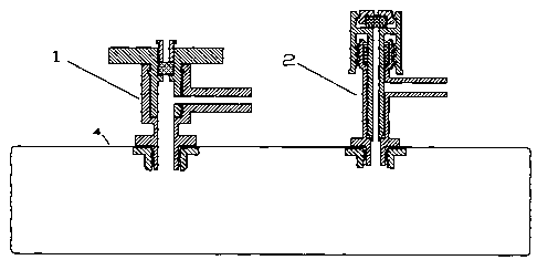
Fig. 1 is a gas sample bag with one stopcock valve 1 and one
needle valve 2.
Fig. 2 is the section view of valve body.
3

CA 02685449 2009-08-13
Fig. 3 is the section view of plug.
Fig. 4 is the section view of stopcock valve in open position.
Fig. 5 is the section view of stopcock valve in close position
Fig. 6 is the section view of needle valve body.
Fig. 7 is the section view of needle.
Fig. 8 is the section view of needle valve in close position.
Fig. 9 is the section of needle valve in open portion.
Description Of The Invention
The invention provides a gas sample bag that has one stopcock
valve and one needle valve. It is convenient to fill gas sample
and withdraw gas sample for analysis. The stopcock valve has
a septum that is used for withdrawing gas sample for analysis.
The needle valve also has a septum that can be used for
withdrawing gas sample for analysis. Both valves have a side
arm that can be used for filling gas sample into the gas sample
bag. The valves can be turned on and off quickly.
In Fig. 1, the gas sample bag consists of FEP film 4, stopcock
valve 1 and needle valve 2.
The stopcock valve 1 comprises two major components, valve
body 5 (Fig. 2) and plug 11 (Fig. 3). Plug 11 has a bore 9. A
septum 10 (Fig. 4) is placed into the middle of plug and is
secured by a stopper 12 (Fig. 4). Stopper 12 has a needle guide
port 13. The stopcock 11 can be rotated.
Valve body 5 has hollow passageway. Upper part of valve
body 5 has a larger diameter passageway 24 acts as housing for
plug 11. A circular groove 7 and a matching ring 14 (Fig.3)
4

CA 02685449 2009-08-13
work together to maintain the position of plug 11 after
assembling. Lower part of valve body 5 has screws and brim 6.
Valve body 5 is installed on the aperture of gas sample bag
film 4 and secured by a nut 3. Valve body 5 has an arm 8 that
has a hollow passageway 25 in it. The arm 8 can be connected
with a flexible plastic tube to fill gas sample into the bag.
To assemble the stopcock 1, plug 11 is placed into housing 24.
When turning plug 11, bore 9 will be aligned to the
passageway 25 in arm 8, therefore the valve is in open position
(shown in Fig.4) and gas sample can communicate inside and
outside of the bag. Gas sample can be filled into the bag by
connecting a flexible silicone tube. When gas sample bag is
full, turn plug 11 clockwise or countclockwise by 90 degree,
the valve is closed, shown in Fig. 5. During manufacturing
process, the surfaces of plug 11 and housing 24 are machined
and polished smoothly and contacted each other seamless.
Lubricant is not required for preventing leakage and potential
contamination from lubricant is eliminated. The stopcock
valve inside doesn't require a rubber O-ring to prevent
leakage. There is no possible contamination from the rubber
O-ring. A portion of gas sample can be withdrawn through port
13 by a syringe for lab analysis.
Needle valve 2 comprises two major components, valve body
15(Fig.6) and needle 16 (Fig. 7). Valve body 15 has an arm 8
that has a hallow passageway 23 in it and two ends that are
threaded. Needle 16 has a narrow bore 17 and U-type threaded
cap 19. A plastic sealing ring 18 is attached to the needle body

CA 02685449 2009-08-13
16. A septum 20 is placed on the top of needle and is secured
by a cap 21, which has a needle guide 22 in it (Fig. 8).
When turning U-type cap 19 clockwise, the needle body moves
down, and the tip of needle touches the inside bore surface of
brim 6. The needle valve is closed (shown in Fig.8). When
turning U-type cap 19 count-clockwise, the needle will moves up
and gap is formed between conic surface of needle and inside
surface of brim 6. Then the valve is open and gas can be filled
through valve arm 8 (shown in Fig. 9).
(o

Representative Drawing
A single figure which represents the drawing illustrating the invention.
Administrative Status

2024-08-01:As part of the Next Generation Patents (NGP) transition, the Canadian Patents Database (CPD) now contains a more detailed Event History, which replicates the Event Log of our new back-office solution.

Please note that "Inactive:" events refers to events no longer in use in our new back-office solution.

For a clearer understanding of the status of the application/patent presented on this page, the site Disclaimer , as well as the definitions for Patent , Event History , Maintenance Fee  and Payment History  should be consulted.

Event History

Description Date
Inactive: Adhoc Request Documented 2013-05-15
Application Not Reinstated by Deadline 2013-04-11
Inactive: Dead - No reply to s.30(2) Rules requisition 2013-04-11
Deemed Abandoned - Failure to Respond to Maintenance Fee Notice 2012-08-13
Inactive: Abandoned - No reply to s.29 Rules requisition 2012-04-11
Inactive: Abandoned - No reply to s.30(2) Rules requisition 2012-04-11
Inactive: S.30(2) Rules - Examiner requisition 2011-10-11
Inactive: S.29 Rules - Examiner requisition 2011-10-11
Letter Sent 2011-08-19
All Requirements for Examination Determined Compliant 2011-08-12
Request for Examination Requirements Determined Compliant 2011-08-12
Request for Examination Received 2011-08-12
Inactive: Office letter 2011-03-21
Change of Address Requirements Determined Compliant 2011-03-21
Change of Address or Method of Correspondence Request Received 2011-03-14
Inactive: Cover page published 2011-02-13
Application Published (Open to Public Inspection) 2011-02-13
Inactive: IPC assigned 2010-03-25
Inactive: First IPC assigned 2010-03-25
Application Received - Regular National 2009-12-10
Filing Requirements Determined Compliant 2009-12-10
Inactive: Office letter 2009-12-10
Inactive: Filing certificate - No RFE (English) 2009-12-10
Small Entity Declaration Determined Compliant 2009-08-13

Abandonment History

Abandonment Date Reason Reinstatement Date
2012-08-13

Maintenance Fee

The last payment was received on 2011-08-15

Note : If the full payment has not been received on or before the date indicated, a further fee may be required which may be one of the following

  • the reinstatement fee;
  • the late payment fee; or
  • additional fee to reverse deemed expiry.

Please refer to the CIPO Patent Fees web page to see all current fee amounts.

Fee History

Fee Type Anniversary Year Due Date Paid Date
Application fee - small 2009-08-13
Request for examination - small 2011-08-12
MF (application, 2nd anniv.) - small 02 2011-08-15 2011-08-15
Owners on Record

Note: Records showing the ownership history in alphabetical order.

Current Owners on Record
CHANGRUN LU
Past Owners on Record
None
Past Owners that do not appear in the "Owners on Record" listing will appear in other documentation within the application.
Documents

To view selected files, please enter reCAPTCHA code :


To view images, click a link in the Document Description column. To download the documents, select one or more checkboxes in the first column and then click the "Download Selected in PDF format (Zip Archive)" or the "Download Selected as Single PDF" button.

List of published and non-published patent-specific documents on the CPD .

If you have any difficulty accessing content, you can call the Client Service Centre at 1-866-997-1936 or send them an e-mail at CIPO Client Service Centre.


Document
Description 
Date
(yyyy-mm-dd) 
Number of pages   Size of Image (KB) 
Description 2009-08-13 6 188
Abstract 2009-08-13 1 15
Claims 2009-08-13 2 28
Drawings 2009-08-13 4 78
Representative drawing 2010-09-20 1 10
Cover Page 2011-02-01 1 36
Filing Certificate (English) 2009-12-10 1 156
Notice: Maintenance Fee Reminder 2011-05-16 1 123
Acknowledgement of Request for Examination 2011-08-19 1 177
Notice: Maintenance Fee Reminder 2012-05-15 1 121
Courtesy - Abandonment Letter (R30(2)) 2012-07-04 1 165
Courtesy - Abandonment Letter (R29) 2012-07-04 1 165
Courtesy - Abandonment Letter (Maintenance Fee) 2012-10-09 1 172
Second Notice: Maintenance Fee Reminder 2013-02-14 1 119
Notice: Maintenance Fee Reminder 2013-05-14 1 129
Correspondence 2009-12-10 1 13
Correspondence 2011-03-14 1 21
Correspondence 2011-03-21 1 15
Fees 2011-08-15 1 20