Note: Descriptions are shown in the official language in which they were submitted.
CA 02685490 2009-10-28
1
WO 2008/138466 PCT/EP2008/003365
CLUTCH ACTUATION DEVICE FOR A MANUAL TRANSMISSION
OF A VEHICLE AND CORRESPONDING CONTROL METHOD
The invention relates to clutch actuation device,
particularly for a manual transmission of a vehicle, in
particular a commercial vehicle, having a clutch
actuation setting device that can be placed in various
positions, on the basis of which a corresponding
operation of a clutch ensues.
The invention further relates to a method for
controlling/regulating a clutch actuation device,
. particularly for a manual transmission of a vehicle, in
particular a commercial vehicle, the clutch actuation
device comprising a clutch actuation setting device
that can be placed in various positions, on the basis
of which a corresponding operation of the clutch
ensues.
In connection with manual transmissions clutch
actuation devices of the generic type usually comprise
clutch actuation setting devices in the form of clutch
pedal devices with foot-operated clutch pedals, which
are generally hydraulically coupled to an operating
cylinder. The hydraulic operating cylinder is in turn
mechanically coupled to a clutch operating device, for
example a central clutch operator, which serves for the
direct operation of a clutch. In order to reduce at
least partially the force that has to be exerted by the
clutch pedal for operation of the clutch, various forms
of clutch servo assistance are generally used. For
example, the clutch pedal device may comprise a so-
called hydraulic master or main cylinder, which is
mechanically coupled to a foot-operated clutch pedal.
In this case a clutch servo embodied as an operating
cylinder may be equipped with a hydraulic slave
cylinder coupled to the master cylinder of the clutch
pedal device. The clutch servo is also at the same time
CA 02685490 2014-10-14
- 2 -
coupled to a pneumatic system, in order to provide clutch
servo assistance through interaction with the slave cylinder.
Provision can also be made for clutch servo assistance
virtually within the clutch pedal device. The clutch pedal
device is accordingly already coupled to the pneumatic system,
in particular the master cylinder of the clutch pedal device,
the master cylinder being coupled to the hydraulic operating
cylinder. Through interaction of the master cylinder with the
pneumatic system, the clutch servo assistance is already
incorporated in the clutch pedal device, which by way of the
hydraulic coupling actuates the operating cylinder, in this
case embodied as a hydraulic slave cylinder. In these clutch
actuation devices of the prior art for manual transmission the
use of the hydraulic actuation or coupling makes no provision
for a clutch or transmission control device or transmission
control electronics. In manual transmissions in commercial
vehicles the clutch is therefore operated at least partially
through the use of such hydraulic systems. Their incorporation
into an overall system, however, makes the overall system very
costly and also expensive to service. Special functions, such
as clutch monitoring functions, clutch closure detection,
clutch wear optimization and clutch overload protection, for
example, can be achieved only at additional cost.
The object of the invention is therefore to develop the clutch
actuation devices of generic type and methods for
controlling/regulating such clutch actuation devices in such a
way that the aforesaid disadvantages
can be at least
partially overcome and in particular so that a clutch
actuation device of increased functionality is created.
The clutch actuation device according to the invention
proceeds from the generic state of the art in that the clutch
actuation setting device is suited to generating electrical
CA 02685490 2014-10-14
- 3 -
signals as a function of its position, on the basis of which
the clutch is correspondingly operated. In this context the
clutch actuation setting device is preferably a clutch pedal
device, which comprises a foot-operated clutch pedal. It is
also equally feasible, however, to use a lever for the clutch
actuation setting, for example in vehicles such as
motorcycles. The electrical signals may be generated by an
inexpensive clutch pedal sensor, for example. The fact that
the clutch actuation setting device only generates and
delivers electrical signals as a function of its position
means that a so-called clutch-by-wire system for manual
transmission is created. The clutch actuation setting device
embodied as a clutch pedal device with clutch pedal therefore
delivers a purely electrical control variable. This affords
the advantage, among other things, that the clutch actuation
device can be mechanically simplified, since no hydraulic
coupling is needed for connecting the clutch pedal device to a
clutch servo or a hydraulic operating cylinder. The absence of
the hydraulic coupling therefore saves both costs and the
overall space required for this coupling. Where the clutch
pedal device comprising a clutch pedal is used, it is possible
by choosing a suitable spring, for example, to generate any
desired counterforce characteristic for operation of the
clutch pedal, since the clutch pedal device is completely
isolated pneumatically and hydraulically and only has an
electrical connection through the clutch pedal sensor.
Inexpensive and simple
CA 02685490 2009-10-28
WO 2008/138466
PCT/EP2008/003365
- 4 -
electrical sensor switches can thereby be used to
generate the electrical signal.
The clutch actuation device according to the invention
can advantageously be developed in that the clutch
actuation setting device is suited to delivering the
electrical signals to a control unit, which on the
basis of the electrical signals causes a pressure to be
applied to a clutch operating device for operation of
the clutch. This makes it possible, for example, to
adjust the degree of pressure applied to the clutch
operating device by way of a valve device. A clutch
regulating device or clutch regulating module is
preferably formed through the integration of the
control unit or control electronics with the valve
device comprising the necessary solenoid valves for
actuation of the clutch operating device. This clutch
regulating module can then preferably be mounted
externally on the manual transmission, in particular on
a clutch bell-housing. This affords greater
interchangeability when servicing. The provision of the
clutch regulating module in connection with the manual
transmission furthermore also makes it possible to
utilize the advantages of an automated clutch control.
For example, it is possible to monitor the clutch plate
wear, since a clutch position can be relayed to the
control unit, for example by way of a CAN bus. It is
furthermore also possible to minimize the clutch plate
wear. This is done by, among other things, calculating
the clutch load as a function of a rotational speed, a
torque, a slip etc. and by a 'harder engagement' of the
clutch on the basis of a correspondingly defined clutch
pedal position; for example when the driver of the
vehicle keeps the clutch in a slipping position for an
unnecessary length of time, so that a full engagement
of the clutch then ensues despite the clutch pedal
being only partially depressed. The clutch regulating
module can also be used to provide an overload
CA 02685490 2009-10-28
WO 2008/138466
PCT/EP2008/003365
- 5 -
protection. Owing to the complete hydraulic, pneumatic
and mechanical isolation of the clutch pedal device
from an operating cylinder, it is possible to achieve
an adjustment of the clutch pedal characteristic, for
example through electronic optimization of the clutch
characteristic curve. In addition all diagnostic
functions can be performed by the clutch regulating
module. Communication with other vehicle control
modules is also possible, for example communication
with a control module of an electronic braking system;
in this case this communication may consist, for
example, in opening the clutch in the event of an
antilock braking mode instituted by an ABS system,
thereby interrupting a power flow in a drivetrain in
the event of ABS control. Similarly communication may
also be provided between ESP electronics or an ESP
control unit for the execution of an electronic
stability program, which serves to interrupt the
drivetrain in the event of ESP control. Communication
can likewise be established with ASC electronics or an
ASC control unit for the acceleration skid control, in
which, for example, an 'automated' starting is
permitted with slipping clutch even when the clutch
pedal is not being operated, in order to prevent wheel
spin on the driving wheels of the vehicle. In addition
it is also possible to achieve an interaction with a
halt brake system or to combine the control/regulation
through the clutch regulating module with a so-called
hill-holder function. Thus when bringing the vehicle to
rest on an incline a braking force is maintained
without the need to operate a parking brake or a
handbrake of the vehicle. At the same time an automated
disengagement of the clutch can be undertaken, if the
driver fails to do this, in order to prevent the
internal combustion engine of the vehicle stalling. The
vehicle is then driven off again by operating an
accelerator pedal, the clutch being automatically
engaged. An interaction is also possible with a
CA 02685490 2009-10-28
WO 2008/138466
PCT/EP2008/003365
- 6 -
transmission control connected to a gearbox servo,
which permits release of the gearbox servo (power-
assisted gearshift) only when the clutch is operated,
for example.
Further advantages also accrue in connection with the
clutch operating device embodied as an operating
cylinder. Thus the operating cylinder may be fitted
externally to a clutch bell housing and preferably
integrated into the clutch regulating module.
Alternatively the operating cylinder may also be
designed separately, for example as a central clutch
operator. A travel or position sensor is preferably
provided directly in the operating cylinder. A separate
evaluation unit for this sensor may be arranged either
in the operating cylinder or also on the clutch
regulating module, for example. In order to enhance the
reliability of such a clutch-by-wire system, redundant
components can be incorporated into the clutch
actuation device. In particular, for example, the
clutch pedal device may deliver two mutually
independent electrical signals for the clutch pedal
position or clutch pedal setting, for example via two
different electrical lines from two corresponding
sensors. Four electrical lines may equally well be
provided, in order to provide the clutch regulating
module with two supply voltages and two ground
connections. This serves at least greatly to reduce any
probability of failure on the part of the clutch
regulating module. With regard to the adjustment of the
pressure applied to the clutch operating device, the
valve device may comprise redundant solenoid valves
both for ventilation and venting of the clutch
operating device. The operating cylinder may likewise
supply the clutch regulating module with two mutually
independent electrical signals for the release travel
of the clutch via two electrical lines.
CA 02685490 2009-10-28
WO 2008/138466
PCT/EP2008/003365
- 7 -
In addition the clutch actuation device according to
the invention can also be embodied so that a valve
device is provided, which is suited to applying a
pressure to the clutch operating device. For example,
the valve device may comprise two ventilation valves,
connected in parallel, for ventilation of the clutch
operating device, one of the two solenoid valves having
a large flow cross section and the other having a small
or smaller flow cross section. The clutch operating
device can therefore be ventilated with different
volumetric flows. Similarly two solenoid valves with
different flow cross sections and connected in parallel
are preferably also used for venting the clutch
operating device. These solenoid valves for ventilation
and venting are, in particular, embodied as 2/2-way
valves.
The clutch actuation device according to the invention
may further be embodied in such a way that the clutch
actuation setting device is suited to generating
further electrical signals as a function of its
position and delivering these further electrical
signals to a further control unit, the further control
unit being suited to delivering the further electrical
signals to the control unit. Provision of the further
control unit serves further to enhance the reliability
of the clutch-by-wire system. In this context the
clutch pedal device preferably delivers two mutually
independent electrical signals, the first signal being
supplied to the control unit, which is assigned to the
clutch regulating module, for example, whilst the
second signal is supplied to the further control unit,
for example via a CAN bus. This further control unit
may in particular be any vehicle control module, which
in turn delivers the further signals to the control
unit assigned to the clutch regulating module, for
example likewise via a CAN bus. Both the control unit
of the clutch regulating module and the further control
CA 02685490 2009-10-28
WO 2008/138466
PCT/EP2008/003365
- 8 -
unit may obviously be in communication with any vehicle
control modules via the CAN bus. In this case, for
example, it is possible to separate the drivetrain of
the vehicle through the clutch when the antilock brake
control is activated by the ABS system.
It is furthermore possible, particularly when a system
failure of the clutch actuation device is registered,
for the drivetrain of the vehicle to be correspondingly
shifted to an idling state either manually via the
gearbox or preferably electronically on the basis of
the corresponding control module, if the manual
transmission is designed to allow this. In this context
it may be particularly advantageous for the manual
transmission, where necessary, to initiate semi-
automatic running if the manual transmission is
designed to allow this. For example, on operation of
the gearshift lever a clutch operation may be triggered
via a sensor, so that the driver no longer needs to
operate the clutch pedal when shifting gear whilst
underway. In this case the clutch pedal is only needed
for driving off and maneuvering.
The clutch actuation device according to the invention
is preferably embodied so that a travel sensor is
provided, which serves to detect a position of the
clutch operating device, and on the basis of the
signals from which it is possible to control/regulate
the clutch operating device.
In this context the clutch actuation device according
to the invention can be developed in such a way that a
pressure sensor is furthermore provided, by means of
which the position of the clutch operating device can
be determined, at least in the event of a failure of
the travel sensor, and on the basis of the signals from
which it is possible to control/regulate the position
of the clutch operating device. Even in the event of a
CA 02685490 2009-10-28
WO 2008/138466
PCT/EP2008/003365
- 9 -
failure of the position or travel sensor in the clutch
operating device, this will allow an emergency control
by way of the pressure sensor incorporated in the
clutch regulating module, for example. However the
pressure sensor may equally well be provided in order
to improve the control quality through interaction with
the travel sensor.
The clutch actuation device may furthermore be embodied
so that one or more of the following components are
accommodated in a housing in a mechatronic unit: the
control unit, the valve device, the travel sensor, the
pressure sensor, and the clutch operating device.
The method according to the invention proceeds from the
generic state of the art in that the clutch actuation
setting device generates electrical signals as a
function of its position, on the basis of which the
clutch is correspondingly operated. In the same or a
similar way this affords the advantages explained in
connection with the clutch actuation device according
to the invention, so that in order to avoid repetition
reference will be made to the corresponding
stipulations in connection with the clutch actuation
device according to the invention.
The same applies analogously to the following preferred
embodiments of the method according to the invention,
so that again in order to avoid repetition reference
will be made to the corresponding stipulations on these
in connection with the clutch actuation device
according to the invention.
The method according to the invention can
advantageously be developed in that the clutch
actuation setting device delivers the electrical
signals to a control unit, which on the basis of the
CA 02685490 2014-10-14
;
- 10 -
electrical signals causes a pressure to be applied to a clutch
operating device for operation of the clutch.
The method according to the invention can furthermore be
embodied so that a valve device applies pressure to the clutch
operating device.
In addition the method according to the invention may be
embodied in such a way that the clutch actuation setting
device generates further electrical signals as a function of
its position and delivers these further electrical signals to
a further control unit, the further control unit being suited
to delivering the further electrical signals to the control
unit.
The method according to the invention can furthermore be
embodied so that a position of the clutch operating device is
detected by means of a travel sensor, and the position of the
clutch operating device is controlled/regulated on the basis
of signals from the travel sensor.
In this context the method according to the invention can be
developed in such a way that by means of a pressure sensor the
position of the clutch operating device can be determined, at
least in the event of a failure of the travel sensor, and the
position of the clutch operating device
is
controlled/regulated on the basis of the signals from the
pressure sensor.
According to an aspect, there is provided a clutch actuation
device, having a clutch actuation setting device, a first
control unit and a second control unit, wherein the clutch
actuation setting device can be placed in various positions,
on the basis of which a corresponding operation of a clutch
CA 02685490 2014-10-14
- 10a -
ensues, the clutch actuation setting device is suited, as a
function of its position, to generating first electrical
signals, on the basis of which the clutch is correspondingly
operated, the clutch actuation setting device is suited to
delivering the first electrical signals to the first control
unit, which on the basis of the electrical signals causes a
pressure to be applied to a clutch operating device
for
operation of the clutch, wherein the clutch actuation setting
device is suited to generating second electrical signals,
independent of the first electrical signals, as a function of
its position and delivering these second electrical signals to
the second control unit, the second control unit being suited
to delivering the second electrical signals to the first
control unit.
According to another aspect, there is provided a method for
controlling/regulating a clutch actuation device, the clutch
actuation device comprising a clutch actuation setting device,
a first control unit and a second control unit, wherein the
clutch actuation setting device that can be placed in various
positions, on the basis of which a corresponding operation of
the clutch ensues, the clutch actuation setting generating as
a function of its position first electrical signals, on the
basis of which the clutch is correspondingly operated, the
clutch actuation setting device delivering the first
electrical signals to the first control unit, which on the
basis of the first electrical signals causes a pressure to be
applied to a clutch operating device for operation of the
clutch, wherein the clutch actuation setting device generates
second electrical signals, independent of the first electrical
signals, as a function of its position and delivers these
second electrical signals to the second control unit, the
second control unit delivering the second electrical signals
to the first control unit.
Mk 02685490 2014-10-14
- 10b -
The invention will now be explained on the basis of preferred
exemplary embodiments, referring to the drawings attached, in
which:
Fig. 1. shows a schematic representation of a clutch actuation
device according to the invention in a first exemplary
embodiment of the invention
CA 02685490 2009-10-28
WO 2008/138466
PCT/EP2008/003365
- 11 -
which is suited to performing the method
according to the invention; and
Fig. 2. shows a schematic representation of a clutch
actuation device according to the invention in a
second exemplary embodiment of the invention which
is suited to performing the method according to
the invention.
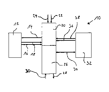
Fig. 1 shows a schematic representation of a clutch
actuation device 10 according to the invention in a
first exemplary embodiment of the invention which is
suited to performing the method according to the
invention. In this exemplary embodiment the clutch
actuation device 10 according to the invention is
intended for a manual transmission of a commercial
vehicle and comprises a clutch actuation setting device
12. The clutch actuation setting device 12 is embodied
as a clutch pedal device with a foot-operated clutch
pedal, which can be operated by a driver of the
commercial vehicle, for example. According to the
invention the clutch actuation setting device 12 is
designed so that it generates electrical signals as a
function of its position, for example the position of
the clutch pedal, and delivers these to a control unit
20. These signals are generated, for example, by a
sensor, in particular a clutch pedal sensor, assigned
to the clutch actuation setting device 12. For this
purpose the clutch actuation setting device 12 is
coupled to the control unit 20 via a power supply lead
14, so that the control unit 20 can supply electrical
current to the clutch actuation setting device 12. The
clutch actuation setting device 12 is furthermore
coupled to the control unit 20 via a signal line 16 and
a further signal line 18, which in particular form two
inverted signal outputs of the clutch actuation setting
device 12, in order to supply the control unit 20 with
signals correlating with a clutch pedal position. The
CA 02685490 2009-10-28
WO 2008/138466
PCT/EP2008/003365
- 12 -
further signal line 18 is here intended to create a
redundancy. Electrical current is delivered to the
control unit 20 via a power supply lead 22 and a
further power supply lead 24, the further power supply
lead 24 being intended to create a redundancy. In the
case shown the control unit 20 is furthermore coupled
to a valve device 26, to which compressed air can be
fed via a valve device ventilation 30 and from which
compressed air can be discharged via a valve device
venting 28. The valve device 26 is here actuated by the
control unit 20, so that the valve device 26 can feed a
defined flow of compressed air to a clutch operating
device 32 by way of the valve device ventilation 30,
and the valve device '26 can discharge a defined flow of
compressed air from the clutch operating device 32 via
the valve device venting 28. For this purpose the valve
device 26 is coupled to the clutch operating device 32
via a coupling 34, in particular a pneumatic line. The
valve device 26 may in this case be a valve device,
known to the person skilled in the art, which comprises
a plurality of 2/2-way valves for proportioning the
ventilation and venting volumetric flows. The clutch
operating device 32 serves for the operation of a
clutch (not shown), that is to say for the engagement
and release of a clutch of a commercial vehicle, and is
embodied, in particular, as a central clutch operator.
In order to determine a position of the clutch
operating device 32, the latter comprises a travel or
position sensor, not shown in Fig. 1, which serves to
detect the position of the clutch operating device. In
this exemplary embodiment the signals from the travel
sensor are delivered to the control unit 20 via a
travel sensor signal line 36 and a further travel
sensor signal line 38, which in particular form two
inverted signal outputs of the travel sensor. The
further travel sensor signal line 38 here again serves
to create a redundancy. The control unit 20 and the
valve device 26 in particular, and optionally also the
CA 02685490 2009-10-28
WO 2008/138466
PCT/EP2008/003365
- 13 -
travel sensor and the clutch operating device 32, are
preferably formed in a housing in a mechatronic unit.
The method according to the invention for
controlling/regulating the clutch actuation device 10
according to the invention is configured as follows. It
is assumed that the driver of the commercial vehicle
intends to change gear using the manual transmission.
For this purpose the driver operates the clutch
actuation setting device 12, in particular the clutch
pedal of the clutch pedal device. The clutch actuation
setting device 12 is thereby brought into a position
which is intended to bring about a complete release of
the clutch and hence an interruption of the power flow
in the drivetrain of the commercial vehicle. The clutch
actuation setting device 12 consequently generates
corresponding electrical signals as a function of this
position and delivers these signals to the control unit
20. The control unit 20 evaluates these signals and in
this case determines that the clutch is to be fully
released. The control unit 20 therefore actuates the
valve device 26 accordingly. The valve device 26
consequently switches its valves over in such a way
that pressure is applied to the clutch operating device
32 for operation of the clutch on the basis of the
actuation by the control unit 20 and hence on the basis
of the electrical signals from the clutch pedal device.
The clutch operating device 32 accordingly operates the
clutch, which undertakes the corresponding complete
release movement and thereby interrupts the power flow
in the drivetrain of the vehicle. This process can be
transferred analogously to all positions of the clutch
ranging from a fully engaged clutch to a fully released
clutch. In order to monitor the exact position of the
clutch, which correlates with the position of the
clutch operating device 32, the clutch operating device
32 comprises the travel sensor (not shown). The travel
sensor therefore determines the exact position of the
CA 02685490 2009-10-28
WO 2008/138466
PCT/EP2008/003365
- 14 -
clutch operating device 32 and delivers signals,
correlating with the position of the clutch operating
device 32, to the control unit 20. On the basis of
these signals from the travel sensor and also as a
function of the electrical signals from the clutch
pedal device the control unit 20 is able to
control/regulate the position of the clutch operating
device 32.
Fig. 2 shows a schematic representation of a clutch
actuation device 100 according to the invention in a
second exemplary embodiment of the invention which is
suited to performing the method according to the
invention. In order to avoid repetition, it is proposed
in the description of this exemplary embodiment to
examine only the differences compared to the first
exemplary embodiment, identical or similar components
of the clutch actuation device 100 being denoted by
similar reference numerals. In this exemplary
embodiment the clutch actuation setting device 112 is
coupled on the one hand to the control unit 120 via a
power supply lead 146 and a signal line 116. On the
other hand the clutch actuation setting device 112 is
coupled to a further control unit 140, for example a
drivetrain control unit, via a power supply lead 114
and a signal line 118. In particular, the clutch
actuation setting device 112 may comprise two mutually
independent sensors, in particular clutch pedal
sensors, which each generate the electrical signals.
The further control unit 140 is furthermore coupled to
the control unit 120 via a CAN bus 148. The clutch
actuation setting device 112 can therefore deliver its
electrical signals to the control unit 120 on the one
hand and to the further control unit 140 on the other.
The further control unit 140 can in turn deliver the
signals supplied to it to the control unit 120 via the
CAN bus 148. Should one of the signal lines 116, 118
and/or one of the power supply leads 146, 114 fail,
CA 02685490 2009-10-28
WO 2008/138466
PCT/EP2008/003365
- 15 -
therefore, the generation of the electrical signals and
the transmission of the electrical signals to the
control unit 120 is assured. The control unit 120
further comprises a pressure sensor 144 for monitoring
a pressure in the clutch operating device 132, for
example by determining the pressure in the valve device
126 or in the coupling 134. In addition the control
unit 120 has a communications interface or multiple
control interfaces 142 for communication with further
control modules of the vehicle, for example with a
control module assigned to an electronic braking system
(EBS). In this exemplary embodiment the control unit 20
and the valve device 126 in particular, and optionally
also the pressure sensor 144 and the clutch operating
device 132, are preferably formed in a housing in a
mechatronic unit.
The method according to the invention for
controlling/regulating the clutch actuation device 100
in this exemplary embodiment differs from that in the
first exemplary embodiment in that the clutch actuation
setting device 112 additionally generates further
electrical signals as a function of its position and
delivers these further electrical signals to the
further control unit 140, the further control unit 140
delivering the further electronic signals to the
control unit 120. In this exemplary embodiment the
control/regulation of the position of the clutch
operating device 132 can also be undertaken on the
basis of signals from the pressure sensor 144. The
pressure sensor 144 serves in particular for
determining the position of the clutch operating device
132 in the event of the travel sensor failing or in
order to improve the control quality, the position of
the clutch operating device 132 being
controlled/regulated on the basis of signals from the
pressure sensor 144 and, in the case of the improvement
in control quality, from the travel sensor.
CA 02685490 2009-10-28
WO 2008/138466 PCT/EP2008/003365
- 16 -
The features of the invention disclosed in the
preceding description, in the drawings and in the
claims may be essential for realization of the
invention both individually and in any combination.
CA 02685490 2009-10-28
WO 2008/138466
PCT/EP2008/003365
- 17 -
List of reference numerals
clutch actuation device
5 12 clutch actuation setting device
14 power supply lead
16 signal line
18 further signal line
control unit
10 22 power supply lead
24 further power supply lead
26 valve device
28 valve device venting
valve device ventilation
15 32 clutch operating device
34 coupling
36 signal line
38 further signal line
100 clutch actuation device
20 112 clutch actuation setting device
114 power supply lead
116 signal line
118 further signal line
120 control unit
25 122 power supply lead
124 further power supply lead
126 valve device
128 valve device venting
130 valve device ventilation
30 132 clutch operating device
134 coupling
136 signal line
140 further control unit
142 communications interface
144 pressure sensor
146 power supply lead
148 CAN bus