Some of the information on this Web page has been provided by external sources. The Government of Canada is not responsible for the accuracy, reliability or currency of the information supplied by external sources. Users wishing to rely upon this information should consult directly with the source of the information. Content provided by external sources is not subject to official languages, privacy and accessibility requirements.
Any discrepancies in the text and image of the Claims and Abstract are due to differing posting times. Text of the Claims and Abstract are posted:
| (12) Patent: | (11) CA 2686732 |
|---|---|
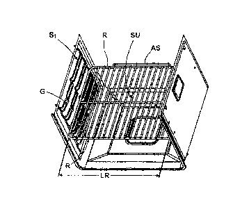
| (54) English Title: | SUPPORT AND SLIDING SYSTEM FOR EXTRACTABLE OVEN SHELVES |
| (54) French Title: | DISPOSITIF DE SUPPORT ET COULISSANT POUR ETAGERES DE FOURNEAUX POUVANT ETRE SORTIES |
| Status: | Expired and beyond the Period of Reversal |
| (51) International Patent Classification (IPC): |
|
|---|---|
| (72) Inventors : |
|
| (73) Owners : |
|
| (71) Applicants : |
|
| (74) Agent: | SMART & BIGGAR LP |
| (74) Associate agent: | |
| (45) Issued: | 2017-05-30 |
| (22) Filed Date: | 2009-12-03 |
| (41) Open to Public Inspection: | 2010-06-18 |
| Examination requested: | 2014-11-10 |
| Availability of licence: | N/A |
| Dedicated to the Public: | N/A |
| (25) Language of filing: | English |
| Patent Cooperation Treaty (PCT): | No |
|---|
| (30) Application Priority Data: | ||||||
|---|---|---|---|---|---|---|
|
A support and sliding system for extractable shelves that are installable in a
cooking
oven that allows maximum sizing of the usable surface of the shelves and the
maximization of the usable volume of the oven cavity.
Un support et un système coulissant pour tablettes extractibles pouvant être installés dans un four qui permet un dimensionnement maximum de la surface utilisable des tablettes et la maximisation du volume utilisable de la cavité du four.
Note: Claims are shown in the official language in which they were submitted.
Note: Descriptions are shown in the official language in which they were submitted.
2024-08-01:As part of the Next Generation Patents (NGP) transition, the Canadian Patents Database (CPD) now contains a more detailed Event History, which replicates the Event Log of our new back-office solution.
Please note that "Inactive:" events refers to events no longer in use in our new back-office solution.
For a clearer understanding of the status of the application/patent presented on this page, the site Disclaimer , as well as the definitions for Patent , Event History , Maintenance Fee and Payment History should be consulted.
| Description | Date |
|---|---|
| Time Limit for Reversal Expired | 2018-12-03 |
| Change of Address or Method of Correspondence Request Received | 2018-01-12 |
| Letter Sent | 2017-12-04 |
| Grant by Issuance | 2017-05-30 |
| Inactive: Cover page published | 2017-05-29 |
| Inactive: Final fee received | 2017-04-05 |
| Pre-grant | 2017-04-05 |
| Notice of Allowance is Issued | 2016-11-01 |
| Letter Sent | 2016-11-01 |
| Notice of Allowance is Issued | 2016-11-01 |
| Inactive: Approved for allowance (AFA) | 2016-10-26 |
| Inactive: Q2 passed | 2016-10-26 |
| Amendment Received - Voluntary Amendment | 2016-05-13 |
| Inactive: S.30(2) Rules - Examiner requisition | 2015-12-17 |
| Inactive: Report - No QC | 2015-12-16 |
| Letter Sent | 2014-11-24 |
| Request for Examination Requirements Determined Compliant | 2014-11-10 |
| All Requirements for Examination Determined Compliant | 2014-11-10 |
| Request for Examination Received | 2014-11-10 |
| Reinstatement Requirements Deemed Compliant for All Abandonment Reasons | 2012-02-03 |
| Letter Sent | 2012-02-03 |
| Deemed Abandoned - Failure to Respond to Maintenance Fee Notice | 2011-12-05 |
| Application Published (Open to Public Inspection) | 2010-06-18 |
| Inactive: Cover page published | 2010-06-17 |
| Inactive: IPC assigned | 2010-02-23 |
| Inactive: First IPC assigned | 2010-02-23 |
| Inactive: Declaration of entitlement - Formalities | 2010-01-22 |
| Inactive: Filing certificate - No RFE (English) | 2010-01-05 |
| Reinstatement Requirements Deemed Compliant for All Abandonment Reasons | 2010-01-05 |
| Application Received - Regular National | 2009-12-22 |
| Abandonment Date | Reason | Reinstatement Date |
|---|---|---|
| 2011-12-05 |
The last payment was received on 2016-11-08
Note : If the full payment has not been received on or before the date indicated, a further fee may be required which may be one of the following
Patent fees are adjusted on the 1st of January every year. The amounts above are the current amounts if received by December 31 of the current year.
Please refer to the CIPO
Patent Fees
web page to see all current fee amounts.
| Fee Type | Anniversary Year | Due Date | Paid Date |
|---|---|---|---|
| Application fee - standard | 2009-12-03 | ||
| MF (application, 2nd anniv.) - standard | 02 | 2011-12-05 | 2012-02-03 |
| Reinstatement | 2012-02-03 | ||
| MF (application, 3rd anniv.) - standard | 03 | 2012-12-03 | 2012-11-30 |
| MF (application, 4th anniv.) - standard | 04 | 2013-12-03 | 2013-11-26 |
| Request for examination - standard | 2014-11-10 | ||
| MF (application, 5th anniv.) - standard | 05 | 2014-12-03 | 2014-11-26 |
| MF (application, 6th anniv.) - standard | 06 | 2015-12-03 | 2015-11-06 |
| MF (application, 7th anniv.) - standard | 07 | 2016-12-05 | 2016-11-08 |
| Final fee - standard | 2017-04-05 |
Note: Records showing the ownership history in alphabetical order.
| Current Owners on Record |
|---|
| WHIRLPOOL CORPORATION |
| Past Owners on Record |
|---|
| CRISTINA MAZZETTI |
| MICHELE VENEZIA |
| STEFANO SALINA |

