Language selection

Search

Patent 2687153 Summary

Third-party information liability

Some of the information on this Web page has been provided by external sources. The Government of Canada is not responsible for the accuracy, reliability or currency of the information supplied by external sources. Users wishing to rely upon this information should consult directly with the source of the information. Content provided by external sources is not subject to official languages, privacy and accessibility requirements.

Claims and Abstract availability

Any discrepancies in the text and image of the Claims and Abstract are due to differing posting times. Text of the Claims and Abstract are posted:

  • At the time the application is open to public inspection;
  • At the time of issue of the patent (grant).
(12) Patent Application: (11) CA 2687153
(54) English Title: ROLLER MILL FOR GRINDING PARTICULATE MATERIAL
(54) French Title: LAMINOIR POUR MEULAGE DE MATERIAU PARTICULAIRE
Status: Dead
Bibliographic Data
Abstracts

English Abstract

A roller mill (1 ) for grinding particulate material such as cement raw materials, cement clinker, coal and similar materials, said roller mill (1 ) comprising a substantially horizontal grinding table (3) and a set of rollers revolving about a vertical shaft (5); said set of rollers comprising a number of rollers (4) rotatable about respective roller axes and being connected via a roller bearing (16) and a roller shaft (6) to the vertical shaft (5), and said set of rollers (4) being configured for interactive operation with the grinding table (3) for application of pressure to the particulate material; characterized in that each roller bearing (16) across its entire axial extent is axially located radially towards the vertical shaft (5) inwardly of the location of the resulting force from the grinding zone imposed upon the respective roller, in use.


French Abstract

L'invention concerne un laminoir (1) pour le meulage de matériau particulaire comme des matières premières de ciment, une scorie de ciment, du charbon et des matériaux similaires, ledit laminoir (1) contenant une table de meulage sensiblement horizontale (3) et un ensemble de cylindres tournant autour d'un arbre vertical (5); ledit ensemble de cylindres comprenant un certain nombre de cylindres (4) rotatifs autour d'axes de cylindre respectifs et connectés par le biais d'un palier de roulement (16) et d'un arbre de cylindre (6) à l'arbre vertical (5), et ledit ensemble de cylindres (4) étant configuré pour interagir avec la table de meulage (3) pour appliquer une pression au matériau particulaire; chaque palier de roulement (16) sur toute son étendue axiale étant dirigé axialement et radialement vers l'arbre vertical (5) rentré vers l'intérieur de l'emplacement de la force résultante à partir de la zone meulage sur laquelle pèse le cylindre respectif, en cours d'utilisation.

Claims

Note: Claims are shown in the official language in which they were submitted.


6

Claims


1. A roller mill (1) for grinding particulate material such as cement raw
materials,
cement clinker, coal and similar materials, said roller mill (1) comprising a
substantially horizontal grinding table (3) and a set of rollers revolving
about a
vertical shaft (5);
said set of rollers comprising a number of rollers (4) rotatable about
respective roller axes and being connected via a roller bearing (16) and a
roller
shaft (6) to the vertical shaft (5), and
said set of rollers (4) being configured for interactive operation with the
grinding table (3) for application of pressure to the particulate material;
characterized in that each roller bearing (16) across its entire axial extent
is axially located radially towards the vertical shaft (5) inwardly of the
location of
the resulting force from the grinding zone imposed upon the respective roller,
in
use.

2. A roller mill according to claim 1, characterized in that the roller
bearing (16) is
formed as a bearing housing (9) comprising at least two rolling bearings (16A,

16B).

3. A roller mill according to claim 2, characterized in that the roller
bearing (16)
further comprises an axial bearing (16C).

4. A roller mill according to claim 1, characterized in that each roller shaft
(6) is
connected to the vertical shaft (5) via a hinged connection (7) with a centre
of
rotation (7a) allowing a free arcuate movement in an upward and downward
direction in a plane including the centreline of the roller shaft.

5. A roller mill according to claim 4, characterized in that the centre of
rotation
(7a) of the hinged connection (7) in a vertical plane is located under the
horizontal plane which comprises the centre of mass (8) of the roller (4),
roller
shaft (6) and the hinge part connected thereto.


7
6. A roller mill according to claim 1 to 5, characterized in that the roller
shaft (6) is
fixedly attached to the roller (4).

7. A roller mill according to any of claims 1 to 6, characterized in that the
roller
shaft (6) for each roller (4) is substantially horizontal.

8. A roller mill according to any of claims 1 to 6, characterized in that the
roller
shaft (6) for each roller (4) has an inclination between 0° and
45° to the horizontal
level.

9. A roller mill according to any of claims 1 to 8, characterized in that each
roller
bearing (16) is located between the respective roller (4) and the vertical
shaft (5).

Description

Note: Descriptions are shown in the official language in which they were submitted.


CA 02687153 2009-11-12
WO 2009/003527 PCT/EP2007/056769
Roller Mill For Grinding Particulate Material

The present invention relates to a roller mill for grinding particulate
material such
as cement raw materials, cement clinker, coal and similar materials, said
roller
mill comprising a substantially horizontal grinding table and a set of rollers
rotating about a vertical shaft, said set of rollers comprising a number of
rollers
rotatable about separate roller axes and being connected via a roller bearing
and
a roller shaft to the vertical shaft, and said set of rollers being configured
for
interactive operation with the grinding table for application of pressure to
the
particulate material.

A roller mill of the aforementioned kind is known, for example, from the UK
patent
No. 601,299. This known mill is designed so that the set of rollers rotate in
one
direction and so that the grinding table rotates in the opposite direction so
as to
increase the capacity of the mill. According to the above-mentioned patent
publication, the rollers are connected to the vertical shaft via a crank-like
connection where each roller is supported by a stationary crank which
protrudes
centrally into the roller. In the publication there is no detailed mention
about how
the roller is supported on the crank, but based on previous knowledge of
roller
mills this is most likely achieved either by means of a slide bearing or a
rolling
bearing provided in the roller itself. With reference to Fig. 1, and as
defined in
the introduction, the roller bearing for each roller is influenced, during the
operation of a roller mill, by the reactions F9,j and Fg,2 from the grinding
force F9
which occurs in the grinding zone between the roller and the grinding table.
Also
a gyro moment M9Yro will be generated about the centre of mass of each roller
in
the plane containing the centre axis of the roller, said gyro moment will
result in
the reaction forces Fgyroj and Fgyro,2 on the roller bearing. The magnitude of
this
gyro moment and hence of the reaction forces depend on the moment of inertia
of the roller and its rotational speed about its separate roller shaft and on
the
rotational speed of the set of rollers about the vertical shaft. As is
apparent from
Fig. 1, the innermost part of the bearing, i.e. that part of the bearing which
is
located closest to the vertical centre shaft will be unilaterally impacted by
the
reaction force FgYro,2 and by a reaction contribution Fg,2 from the grinding
force.


CA 02687153 2009-11-12
WO 2009/003527 PCT/EP2007/056769
2
Hence, the total load imposed upon this part of the bearing may be quite
substantial, resulting in early-stage wearing-down and/or breakdown of the
bearing.

It is the object of the present invention to provide a roller mill by means of
which
the aforementioned disadvantage is reduced.

This is obtained by means of a roller mill of the kind mentioned in the
introduction
and being characterized in that each roller bearing across its entire axial
extent is
axially located radially towards the vertical shaft inwardly of the location
of the
resulting force from the grinding zone imposed upon the respective roller, in
use.
As a result, the load incurred by the entire bearing and in particular by the
innermost part hereof will be reduced since the reaction forces from the gyro
moment and the grinding force will have a partial and mutually neutralizing
effect
across the entire axial extent of the bearing.

In principle, the roller bearing may be constituted by any suitable bearing
and in a
simple embodiment it may be constituted by a slide bearing which for example
is
formed as a bearing housing with a circular-cylindrical bearing shell in which
the
roller shaft is turning. However, it is preferred that the roller bearing is
formed as
a bearing housing comprising at least two rolling bearings. It is further
preferred
that the roller bearing comprises an axial bearing.

Each roller shaft is preferably connected to the vertical shaft via a hinged
connection with a centre of rotation allowing a free arcuate movement in
upward
and downward direction in a plane comprising the centreline of the roller
shaft.
This will cause the gyro moment to contribute to the grinding force acting
upon
the particulate material. The plane in which the roller moves does not
necessarily include the centreline of the vertical shaft. To obtain a minor
sliding or
shearing effect in the grinding zone the roller is sometimes or quite often
slightly
angled, meaning that its centreline does not always pass through the
centreline
of the vertical shaft.


CA 02687153 2009-11-12
WO 2009/003527 PCT/EP2007/056769
3
As is the case in previously known roller mills, the roller shaft itself may
be
stationary but in order to ensure maximum contribution to the grinding force
from
the gyro moment, it is preferred that the roller shaft is fixedly attached to
the
roller.

It is further preferred that the centre of rotation of the hinged connection
in a
vertical plane is located under the horizontal plane which comprises the
centre of
mass of the roller, roller shaft and the hinge part connected thereto so that
the
centrifugal force acting upon these machine parts during the operation of the
mill
will generate a turning moment about the hinge and hence a force which is
directed downward against the grinding table.

In principle, the roller mill may be formed with inclined roller shafts, e.g.
with an
inclination between 00 and 450 to the horizontal level, so that, in accordance
with
the aforementioned, the centrifugal force acting upon each roller will
positively
contribute towards the grinding pressure when the centre of rotation of the
hinged
connection is located under the horizontal plane which comprises the centre of
mass of the roller, the roller shaft and the hinge part connected thereto.
However, the drawback associated with inclined roller shafts is that the force
contributed by the gyroscopic effect is hereby reduced. According to the
invention, it is therefore preferred that the roller shaft for each roller is
substantially horizontal.
The invention will now be explained in further details with reference to the
drawing, being diagrammatical, and where

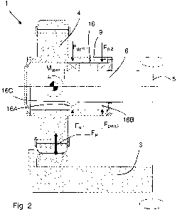
Fig. 1 shows a sectional view of a known roller mill,
Figs. 2 and 3 show two embodiment examples of a roller mill according to the
invention, and


CA 02687153 2009-11-12
WO 2009/003527 PCT/EP2007/056769
4
Fig. 4 shows a preferred embodiment of the roller mill according to the
invention.
In Fig. 1 to Fig. 4 of the drawing, the same reference designations are used
for
corresponding parts. In all four figures a sectional view is given of a roller
mill 1
which comprises a horizontal grinding table 3 and a set of rollers 4 operating
interactively therewith, with only one of these rollers actually shown, and
being
connected to and rotating about a vertical shaft 5.

In the roller mill shown in Fig. 1, the rollers 4 are supported on each
horizontal
roller shaft by means of a bearing 16 comprising two rolling bearings 16A and
16B which are axially positioned on separate sides in relation to the
resulting
grinding force Fg from the grinding zone which acts upon the roller. As is
apparent from Fig. 1, the rolling bearings 16A and 16B will during the
operation of
the roller mill be influenced by the reactions Fg,j and Fg,2 from the grinding
force
Fg which occurs in the grinding zone between the roller and the grinding
table,
and by the reaction forces F9Yro,j and Fgyro,2 resulting from the gyro moment
Mgyro
acting about the centre of mass of the roller. As is seen in Fig. 1, the
rolling
bearing 16B is unilaterally loaded by the reaction force Fgyro,2 and by the
reaction
contribution F92 2 from the grinding force which is undesirable since this may
cause the total load incurred by this bearing to be quite significant,
entailing
early-stage wearing-out and/or breakdown of the bearing.

According to the invention, across its entire axial extent each roller bearing
16 is
axially located within the resulting force Fg acting upon the roller 4 from
the
grinding zone, thereby decreasing the load incurred by the entire bearing 16
and
particularly the innermost part hereof since the forces of reaction from the
gyro
moment and the grinding force will have a partial and mutually neutralizing
effect
across the entire axial extent of the bearing in the manner shown in the
Figures 2
to 4.
In the embodiment shown in Fig.2, the roller shaft 6 is stationary as is the
case in
Fig. 1, being supported by means of a bearing 16 comprising two rolling
bearings
16A and 16B. The embodiment shown in Fig. 2 is different from that shown in


CA 02687153 2009-11-12
WO 2009/003527 PCT/EP2007/056769
Fig. 1 in that the roller 4 is formed with a bearing housing 9 extending
axially
inward towards the vertical shaft 5 from the inner side of the roller 4. As a
result
hereof, both rolling bearings 16A and 16B can be axially fitted within the
resulting
force Fg acting upon the roller 4. The roller shaft 6 also incorporates a
flange 16C
5 acting as an axial bearing face.

In the embodiment shown in Fig. 3 the roller shaft 6 is fixedly attached to
the
roller 4 and comprises a flange 16C which acts as an axial bearing face.
A preferred embodiment of the invention is shown in Fig. 4. In this
embodiment,
each roller shaft 6 is connected to the vertical shaft 5 via a hinged
connection 7
with a centre of rotation 7a allowing a free circular movement of the roller
upward
and downward in a plane comprising the centreline of the roller shaft. As a
result,
the gyro moment will contribute to the grinding force Fg acting upon the
particulate material. As in Fig. 3, the roller shaft is also fixedly attached
to the
roller 4 so that it turns simultaneously with the roller 4, thereby
contributing to the
grinding force generated by the gyro moment. The centre of rotation 7a of the
hinged connection 7, viewed in a vertical plane, is also located under the
horizontal plane which comprises the centre of mass 8 of the roller 4, the
roller
shaft 6 and the hinge part connected thereto so that the centrifugal force,
which
during the operation of the mill acts upon the roller 4, the roller shaft 4,
the roller
shaft 6 and the hinge part connected thereto, will also produce a turning
moment
about the hinge 7 and hence a downwardly directed contribution to the grinding
force Fg.

Representative Drawing
A single figure which represents the drawing illustrating the invention.
Administrative Status

For a clearer understanding of the status of the application/patent presented on this page, the site Disclaimer , as well as the definitions for Patent , Administrative Status , Maintenance Fee  and Payment History  should be consulted.

Administrative Status

Title Date
Forecasted Issue Date Unavailable
(86) PCT Filing Date 2007-07-04
(87) PCT Publication Date 2009-01-08
(85) National Entry 2009-11-12
Examination Requested 2012-06-22
Dead Application 2014-07-04

Abandonment History

Abandonment Date Reason Reinstatement Date
2013-07-04 FAILURE TO PAY APPLICATION MAINTENANCE FEE

Payment History

Fee Type Anniversary Year Due Date Amount Paid Paid Date
Application Fee $400.00 2009-11-12
Maintenance Fee - Application - New Act 2 2009-07-06 $100.00 2009-11-12
Maintenance Fee - Application - New Act 3 2010-07-05 $100.00 2010-06-22
Maintenance Fee - Application - New Act 4 2011-07-04 $100.00 2011-06-21
Maintenance Fee - Application - New Act 5 2012-07-04 $200.00 2012-06-11
Request for Examination $800.00 2012-06-22
Owners on Record

Note: Records showing the ownership history in alphabetical order.

Current Owners on Record
FLSMIDTH A/S
Past Owners on Record
HANGHOEJ, SOEREN
OLSEN, MORTEN
Past Owners that do not appear in the "Owners on Record" listing will appear in other documentation within the application.
Documents

To view selected files, please enter reCAPTCHA code :


To view images, click a link in the Document Description column. To download the documents, select one or more checkboxes in the first column and then click the "Download Selected in PDF format (Zip Archive)" or the "Download Selected as Single PDF" button.

List of published and non-published patent-specific documents on the CPD .

If you have any difficulty accessing content, you can call the Client Service Centre at 1-866-997-1936 or send them an e-mail at CIPO Client Service Centre.


Document
Description 
Date
(yyyy-mm-dd) 
Number of pages   Size of Image (KB) 
Abstract 2009-11-12 1 68
Claims 2009-11-12 2 58
Drawings 2009-11-12 2 96
Description 2009-11-12 5 241
Representative Drawing 2010-01-12 1 16
Cover Page 2010-01-13 2 54
PCT 2009-11-12 3 80
Assignment 2009-11-12 3 95
Prosecution-Amendment 2012-06-22 2 73
PCT 2012-07-05 4 154