Note: Descriptions are shown in the official language in which they were submitted.
CA 02688451 2009-11-27
WO 2008/148419 PCT/EP2007/055478
-1-
PRESSURE SWIRL ATOMIZING NOZZLE FOR SPRAYING A CURABLE COMPOSITION AND
ASSOCIATED METHOD AND USE
The present invention relates to a pressure swirl atomizing
nozzle as defined in the preamble of claim 1 for spraying a curable
composition onto a surface to produce a polymeric layer thereon. The
invention also relates to a method for spraying the curable composition
onto a surface, in which method use is made of the nozzle according to
the invention.
The curable composition is in particular a polyurethane
reaction mixture which is sprayed onto a mould surface to produce for
example interior trim parts or panels for automobiles such as dashboards,
door panels, glove compartment covers, consoles, etc. Such
polyurethane reaction mixtures usually have a relatively high viscosity
and hence are quite difficult to atomize.
A pressure swirl atomizing nozzle for spraying a layer of a
polyurethane reaction mixture onto a mould surface as defined in the
preamble of claim 1 is already disclosed in EP-B-0 303 305 and EP-B-
0 389 014. The nozzles disclosed in these patents comprise an orifice
piece that defines a funnel-shaped cavity ending in the exit orifice of the
nozzle. At its upstream extremity, the funnel-shaped cavity is closed off
by an injector piece so that a swirl chamber is formed between the front
side of the injector piece and the exit orifice. The injector piece comprises
two or more swirl ports through which the curable composition is injected
into the swirl chamber. Due to the obtained swirling motion, the curable
composition is sprayed out of the exit orifice in the form of a hollow spray
cone.
CA 02688451 2009-11-27
WO 2008/148419 PCT/EP2007/055478
-2-
When using the nozzles disclosed in these prior art patents
for spraying a layer of a curable composition onto complex mould
surfaces, in particular onto mould surfaces which show cavities, the
nozzles should be made quite small so that they can be moved within
narrow cavities whilst maintaining a sufficient spray distance. Moreover,
the flow rate of the curable composition should be quite low so that, even
when spraying from a short distance, a thin layer of curable composition
can be applied uniformly onto the mould surface. The curable
composition may further not be atomized into a too fine mist to avoid
overspray.
When spraying the curable composition onto mould
surfaces, it is desirable to vary the flow rate of the curable composition
without influencing the spray pattern (droplet size, stability of the spray
pattern, i.e. the kinetic energy of the curable composition) too much. This
would allow to reduce the flow rate of the curable composition when
spraying from a short spray distance, for example at the edges or in
narrow cavities, and to increase the flow rate of the curable composition
when spraying from a greater spray distance, onto a larger surface. In
this way, it is possible to spray a layer having a more uniform thickness
and to reduce overspray without increasing the cycle time too much.
Tests performed by the present inventors with nozzles as
disclosed in EP-B-0 303 305 and EP-B-0 389 014 have shown that when
spraying a polyurethane reaction mixture at such a pressure that it is
atomized into droplets having an MVD of about 95 pm, a reduction of the
applied pressure by 40% resulted in a decrease of the flow rate by about
30% and in an increase of the MVD of the sprayed droplets by about 65%
(MVD is the medium volume diameter of the droplets as determined in
accordance with ASTM E 799-81). This increase of the droplet size is
much higher than observed for example when atomizing fuel oils.
According to the article "Fuel Nozzles for Oil Burners" by E. O. Olson
CA 02688451 2009-11-27
WO 2008/148419 PCT/EP2007/055478
-3-
(Delavan), research has shown that the median droplet size varies
inversely as the 0.3 power of the pressure change. A pressure reduction
of 40% would thus correspond to an increase of the droplet size by about
16%, which is much smaller than the droplet size increase observed in
practice for polyurethane reaction mixtures.
A first drawback of the larger droplet size is that bigger air
bubbles will be included in the sprayed layer leading to worse mechanical
properties. A further drawback is that a spray pattern formed by larger
droplets is less stable and will be more easily disturbed by gravity or air
currents, so that a thicker layer will need to be sprayed to obtain a
uniform layer with the desired mechanical properties.
In practice there exist already so-called variable flow
nozzles, such as bypass or return flow nozzles, air atomizing nozzles,
dual orifice type nozzles and duplex nozzles. These nozzles enable a
larger variation of the flow rate through the nozzle but are not suited at all
for spraying curable compositions. Moreover, they are relatively
voluminous.
A nozzle which is suitable for spraying a polyurethane
reaction mixture at a variable flow rate is disclosed in WO-A-
2005/000481. In order to enable to vary the flow rate of the reaction
mixture, an amount of a pressurized gas is added thereto. In this way,
due to the volume of gas, the flow rate of the polyurethane reaction
mixture can be reduced and it can be varied by varying at the same time
also the amount of pressurized gas added thereto. The spray equipment
related to this gas-assisted spray process is however more complex and
expensive.
An object of a first aspect of the present invention is to
provide a new pressure swirl nozzle which enables to spray the curable
composition at a relatively low flow rate so that relatively coarse droplets
CA 02688451 2009-11-27
WO 2008/148419 PCT/EP2007/055478
-4-
are produced and which enables to reduce the effect of a variation of this
relatively low flow rate on the size of the sprayed droplets.
To this end, the nozzle according to the first aspect of the
invention is characterised in that the injector piece is situated at such a
distance from the exit orifice that
6 < A_ cos ~ < 17 and in that
Asp, tot
the ratio Lo/Do is smaller than 1, with
Asc = the surface area, in mm2, of the side wall of the swirl
chamber;
= the inclination angle of the swirl ports;
AsP,tot= the sum of the smallest cross-sectional areas AsP, in mm2, of
the swirl ports measured in a cross-sectional plane
perpendicular to the predetermined overall direction wherein
the curable composition is injected through the respective
swirl port in the swirl chamber;
Lo = the length of the exit orifice, in mm;
Do = the diameter of the exit orifice, in mm; and
< = smaller or equal to.
It has been found that when positioning the injector piece
closer to the exit orifice, i.e. when reducing the surface area As, of the
side wall of the swirl chamber, a decrease of the flow rate has a smaller
effect on the droplet size. The surface area As, should more particularly
be so small that A_ * cos < 17, preferably <_ 15, more preferably <_ 13
Asp, tot
and most preferably <_ 12.
The ratio As~ * cos P can also be reduced by increasing the
Asp, tot
cross-sectional surface area AsP,tot of the swirl ports. However, this will
result in higher flow rates. Since the nozzle according to the invention is
CA 02688451 2009-11-27
WO 2008/148419 PCT/EP2007/055478
-5-
intended for spraying at relatively small flow rates, the sum AsP,tot of the
smallest cross-sectional areas AP of the swirl ports has to be smaller than
0.9 mm2 and preferably even smaller than 0.6 mm2.
The surface area As, of the side wall of the swirl chamber
cannot be reduced unlimitedly. Indeed, a minimum surface area is
required to be able to obtain a uniform spray pattern. In this respect, it
has been found that the ratio As~ * cos P should be greater than or equal
AsP, tot
to 6, preferably _ 7, more preferably _ 8 and most preferably _ 8.5.
To reduce the effect of the flow rate on the droplet size, the
ratio Lo/Do should finally be smaller than 1, preferably smaller than 0.6,
more preferably smaller than 0.5 and most preferably smaller than 0.4.
In a preferred embodiment of the nozzle according to the
invention, the smallest cross-sectional area of each of said swirl ports,
measured in a cross-sectional plane perpendicular to the predetermined
overall direction wherein the curable composition is injected by the swirl
port into the swirl chamber, is greater than 0.07 mm2, preferably greater
than 0.08 mm2, but smaller than 0.25 mm2, preferably smaller than
0.20 mm2 and more preferably smaller than 0.15 mm2.
In order to reduce the risk of clogging of the swirl ports, for
example by bits of (partially) cured curable composition, the cross-
sectional area of each of the swirl ports should be large enough.
However, the smaller the cross-sectional area of each of the swirl ports,
the more swirl ports can be provided and the more evenly the curable
composition is distributed over the side wall of the swirl chamber. This is
important in view of being able to obtain a uniform spray pattern wherein
the curable composition is evenly distributed.
In a further aspect of the invention, when projected at right
angles onto a further longitudinal plane comprising said longitudinal axis
and a straight line which intersects said longitudinal axis perpendicularly
CA 02688451 2009-11-27
WO 2008/148419 PCT/EP2007/055478
-6-
and which passes through the centre of the outlet of the respective swirl
port, the predetermined overall directions wherein the curable
composition is injected out of the swirl ports into the swirl chamber form
an angle y with said transverse plane B perpendicular to said longitudinal
axis which is at least 8 , preferably at least 12 larger than the average
angle aav formed by the side wall of the swirl chamber with said
transverse plane B.
Due to the fact that the curable composition is injected
under an angle against the side wall of the swirl chamber, an improved
uniformity of the spray pattern is obtained.
The present invention also relates to a method for producing
a polymeric layer on a surface by spraying a curable composition thereon
by means of a pressure swirl atomizing nozzle. This method is
characterised in that use is made of a pressure swirl atomizing nozzle
according to the invention.
Other particularities and advantages of the invention will
become apparent from the following description of some particular
embodiments of the nozzle and of the method according to the present
invention. The reference numerals used in this description relate to the
annexed drawings wherein:
Figure 1 is a schematic diagram showing the principle of
spraying a polyurethane reaction mixture onto a mould surface with a
nozzle according to the present invention;
Figure 2 shows a schematic side view of a spray pattern
which can be achieved by a nozzle according to the present invention,
the reaction mixture being sprayed in the form of a hollow cone;
Figure 3 is a cross-sectional view through a nozzle
according to the present invention;
Figure 4 is a top plan view on the nozzle shown in Figure 3;
CA 02688451 2009-11-27
WO 2008/148419 PCT/EP2007/055478
-7-
Figure 5 is a top plan view on the injector piece of the
nozzle shown in Figures 3 and 4;
Figure 6 is a side view on the injector piece shown in Figure
5;
Figure 7 is, on a larger scale, a cross-sectional view through
the orifice piece and the injector piece of the nozzle illustrated in Figure
3;
and
Figures 8 and 9 are similar to Figure 7 but show variant
embodiments.
The present invention relates to a pressure swirl atomizing
nozzle, and to a method for spraying method a curable composition by
means of this nozzle onto a surface to produce a polymeric layer thereon.
The nozzle is a so-called airiess spray nozzle, i.e. a nozzle wherein no
gas is added in order to influence the spray pattern. The curable
composition is in particular a reactive mixture of components producing
polyurethane, called herein a polyurethane reaction mixture. The curable
composition may optionally contain a physical or chemical blowing agent
which provides for a foaming of the layer of curable composition
deposited on the surface. Although other curable compositions such as
silicone resins, epoxy resins and phenolic resins can also be sprayed, the
further detailed description will be made with reference to the spraying of
polyurethane reaction mixtures. Such mixtures are usually obtained by
mixing two components, namely an isocyanate component and a polyol
component, although it is possible to use more than two component
streams. The sprayed polyurethane reaction mixture preferably
comprises no solvents (including water), or only a small amount of
solvents, in particular less than 10% by weight, more particularly less
than 5% by weight, so that the reaction mixture, when being sprayed, has
a relatively high viscosity.
CA 02688451 2009-11-27
WO 2008/148419 PCT/EP2007/055478
-8-
The sprayed polyurethane layer has usually an average
density higher than 300 g/l, preferably higher than 400 g/l and most
preferably higher than 600 g/l. The polyurethane layer may be a rigid
polyurethane layer but it is preferably a flexible elastomeric polyurethane
layer, in particular a so-called polyurethane skin having preferably an
average thickness (determined by dividing the volume of the skin by its
surface area) in the range of 0.1 to 3 mm, preferably 0.3 to 2 mm. In
practice, especially in order to produce an interior trim part for automotive
vehicles such as a dash board, a door panel, a console, etc., a rigid
backing layer is applied behind such skin layer and, between both layers
preferably an intermediate foam layer.
Reaction mixtures for spraying a polyurethane skin are
disclosed for example in EP-B-0 379 246. These reaction mixtures are
composed by mixing an isocyanate component and a polyol component
just before spraying the reaction mixture. The isocyanate component may
be based on aliphatic isocyanates in order to achieve a light-stable
polyurethane skin. In practice, it is however also possible to spray a
polyurethane skin which is not light-stable. In the reaction mixture for
such skins, use is made of more reactive aromatic polyisocyanates. In
this case a paint layer is preferably applied onto such skins either after
having produced the skin or by applying the paint layer onto the mould
surface as an in-mould coating before spraying the reaction mixture for
the skin onto the mould surface, in order to render the skins light-stable.
The basic principle for spraying the polyurethane reaction
mixture is illustrated in Figure 1.
In a first step, the two components, namely the polyol and
the isocyanate component, are dosed from stirrer tanks 1A and 1 B by
means of pumps 2A and 2B and are heated to the desired temperature in
heat exchangers 3A and 3B before being mixed in a movable spray gun
4, provided with a spray nozzle 5. From this spray nozzle 5 the reaction
CA 02688451 2009-11-27
WO 2008/148419 PCT/EP2007/055478
-9-
mixture is sprayed according to a predetermined spray pattern onto a
surface, in particular a mould surface 6. After having cured the reaction
mixture, the formed polyurethane layer 9 can be removed from the mould
surface 6, optionally after having applied one or more additional layers
onto the back of the sprayed polyurethane layer 9. The polyurethane
layer does not necessarily have to be sprayed onto a mould surface but
can also be sprayed against another layer of the moulded article which is
to be produced, for example against an in-mould coating layer or against
an outer skin layer which has already been sprayed onto the mould
surface and which may also be a polyurethane layer. This outer
polyurethane layer can also be sprayed by means of a nozzle according
to the invention and may for example be an aliphatic layer whilst the inner
layer is an aromatic polyurethane layer. The inner layer may have a same
density as the outer layer but it can also have a lower density.
When spraying the viscous reaction mixture out of the
nozzle 5, the obtained spray pattern usually consists of a film 7 which
falls apart into droplets 8 after a certain distance d of for example 0.5 to
cm. The spray process is preferably controlled in such a manner that
this reaction mixture is sprayed out of the nozzle either directly in the
20 form of droplets 8 which have a medium volume diameter (MVD),
determined according to ASTM E 799-81, larger than 50 m, preferably
larger than 60 pm, more preferably larger than 70 pm and most
preferably larger than 80 pm, or in the form of a film 7 which falls apart
into such droplets 8 at a distance d from the nozzle 5. The spray process
is further preferably controlled in such a manner that the droplets 8 have
a medium volume diameter smaller than 500 m, preferably smaller than
300 m, more preferably smaller than 200 pm and most preferably
smaller than 150 m. When spraying in narrow cavities, it is possible that
the distance between the nozzle and the mould surface, i.e. the spray
distance D, is smaller than the distance d after which the film falls apart
CA 02688451 2009-11-27
WO 2008/148419 PCT/EP2007/055478
-10-
into droplets so that the reaction mixture arrives onto the mould surface 6
in the form of the film 7.
The reaction mixture is sprayed in the shape of a round or
elliptical cone which is preferably hollow. A hollow cone shaped spray
pattern has been illustrated in Figure 2 and is preferred in view of the fact
that it enables to achieve a more uniform layer thickness.
The polyurethane layer is preferably sprayed onto the mould
surface in two or more phases. In a first phase, the polyurethane reaction
mixture is preferably sprayed at a higher flow rate, usually from a greater
spray distance D. In a next phase, the flow rate is preferably reduced so
that the spray distance D can be decreased to spray more complexly
shaped portions of the mould surface or to spray the edges thereof. In
this way it is possible to achieve a more uniform layer thickness and to
reduce overspray. The ratio between the highest and the lowest flow rate
applied when spraying the polyurethane layer is preferably _ 1.1, in
particular _ 1.2, and more in particular _ 1.3.
As explained hereabove, the curable composition is
composed by mixing at least two components, in particular a polyol and
an isocyanate component, in a predetermined ratio. During the transition
from one flow rate to another flow rate the operation of the pumps 2A and
2B is preferably controlled in such a manner that the ratio between the
reaction components is preferably also maintained constant when varying
the flow rate. In this way, it is not necessary to interrupt spraying of the
polymeric layer when switching from one flow rate to another. This offers
the advantage that no material is lost during the switching between the
different flow rates. When spraying the skin of a common instrument
panel, a material saving of about 10% can be achieved whilst the spray
time was only increased with about 5%.
When lowering the flow rate, it is desirable that the droplet
size does not become too large to avoid that too big air enclosures would
CA 02688451 2009-11-27
WO 2008/148419 PCT/EP2007/055478
-11-
be incorporated in the sprayed layer and to prevent an unstable spray
pattern. On the other hand, when increasing the flow rate, it is desirable
that the droplet size does not become too small to avoid a too fine mist.
Both when spraying at the highest and at the lowest flow rate, the
medium volume diameter of the produced droplets should preferably be
within the ranges described hereabove.
According to the present invention, a new nozzle is provided
which enables to vary the flow rate of the curable composition through
the nozzle with a reduced effect on the droplet size.
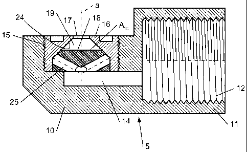
Figure 3 illustrates a first embodiment of a pressure swirl
atomizing nozzle according to the present invention. This spray nozzle 5
comprises a housing 10 having a tubular end 11 provided with an internal
screw thread 12 by means of which it can be screwed onto the distal end
of a static mixer 13 of the spray gun 4. The housing 10 is further provided
with a longitudinal bore 14, forming a supply channel ending in a larger,
transverse bore 15 which has an open end. The inner surface of the
transverse bore 15 is screw threaded and an orifice piece 16, provided
with a corresponding screw thread, is screwed into this bore 15.
The orifice piece 16 is a hollow piece which is open at the
bottom and which defines a funnel-shaped cavity and, at its top, an exit
orifice 17. The funnel-shaped cavity has a longitudinal axis a passing
through the centre of the exit orifice 17. An injector piece 18 is inserted
through its open bottom into the orifice piece 17 to close off this funnel-
shaped cavity at its upstream extremity. In this way, the funnel-shaped
cavity forms a swirl chamber 19 between the front side of the injector
piece 18 and the exit orifice 17.
In the embodiment illustrated in the figures, the side wall 24
of the swirl chamber 19, i.e. the inner surface of the funnel-shaped cavity,
is conical and forms in longitudinal sections through the longitudinal axis
a of the funnel-shaped cavity an angle a, which is generally comprised
CA 02688451 2009-11-27
WO 2008/148419 PCT/EP2007/055478
-12-
between 30 and 60 , with a transverse plane B perpendicular to this
longitudinal axis a. If the angle a is not constant, for example due to the
fact that the side wall is curved when seen in said longitudinal sections,
the average angle aav should be comprised between 30 and 60 , the
average angle aav being a surface-weighted average taking into account
the surface area of the side wall showing a same angle a. In the
embodiment illustrated in Figure 8, a first portion 24' of the side wall 24,
situated adjacent the injector piece 18, forms an angle a' with the
transverse plane B whilst a second portion 24" of the side wall 24,
situated adjacent the exit orifice 17, forms an angle a' with this transverse
plane B. When the first portion 24' has a surface area A, and the second
A * W * ~~
portion 24" a surface area A2, aav is equal to ' A+A a. For a curved
,
z
side wall 24, as illustrated in Figure 9, the average angle aav can be
calculated in a similar way.
The injector piece 18 comprises four swirl ports 20 (i.e. 20a,
20b, 20c and 20d), through which the reaction mixture, which is supplied
through the longitudinal bore 14, is injected into the swirl chamber 19
according to a predetermined overall direction, indicated by the general
speed vectors 21. As illustrated in Figures 5 and 6 the injector piece 18
consists for example of a cylindrical portion 22 and a frustoconical portion
23 fitting within the hollow orifice piece 16, the frustoconical portion 23
fitting more particularly against the conical inner surface of the orifice
piece 16. In the frustoconical upper surface four grooves are made
forming the swirl ports 20. Each of these grooves or swirl ports 20 is
connected by a cylindrical boring 25, which ends centrally in the bottom
side of the injector piece 18, to the supply channel 14 so that the flow of
reaction mixture is split over the four borings 25 and swirl ports 20.
The swirl ports 20 are oriented so that the predetermined
overall direction 21 wherein the reaction mixture is injected in the swirl
CA 02688451 2009-11-27
WO 2008/148419 PCT/EP2007/055478
-13-
chamber 19 forms, when projected at right angles onto a longitudinal
plane A comprising the longitudinal axis a of the funnel-shaped cavity and
being perpendicular to a straight line b which intersects said longitudinal
axis a perpendicularly and which passes through the centre c of the outlet
of the respective swirl port 20, an angle ,6 with a transverse plane B
perpendicular to said longitudinal axis a, the angle ,6 being comprised
between 30 and 600. Since in the representation of Figure 6 the angle ,6
can be seen for the swirl port 20a, the longitudinal plane A, the centre c
and the straight line b used for determining the angle ,6 have been
illustrated in Figures 5 and 6 for this swirl port 20a.
The swirl ports 20 preferably have a cross-sectional area,
measured in a cross-sectional plane C (illustrated for swirl port 20b)
perpendicular to the predetermined overall direction 21 wherein the
reaction mixture is injected by the respective swirl port 20 in the swirl
chamber 20, which is not constant but which decreases towards the swirl
chamber 20. In this way the pressure drop over the nozzle is reduced. In
the embodiment illustrated in Figures 5 and 6, the decreasing cross-
sectional area of the grooves is achieved by the fact that the depth of the
swirl ports 20, measured perpendicular to the side wall of the funnel-
shaped cavity, decreases towards the swirl chamber 19. Due to the fact
that the cross-sectional area of the swirl ports 20 is not constant, the
direction of flow of the reaction mixture differs over the cross-section of
the swirl ports 20 so that the predetermined overall direction 21 wherein
the reaction mixture is injected in the swirl chamber 19 corresponds to
the general speed vector of the reaction mixture leaving the swirl port 20
(the general speed vector is determined assuming a uniform speed
magnitude of the reaction mixture across the entire cross-section of the
swirl port).
The depth of the swirl ports 20 decreases to such an extent
towards the swirl chamber 19 that the predetermined overall direction 21
CA 02688451 2009-11-27
WO 2008/148419 PCT/EP2007/055478
-14-
wherein the reaction mixture is injected in the swirl chamber 19 forms an
angle y with said transverse plane B, perpendicular to the longitudinal
axis a of the swirl chamber 19, which is larger than the angle a or the
average angle aav formed between the side wall 24 of the swirl chamber
19 and the transverse plane B. The angle y can be seen for swirl port 20b
in Figure 6. To determine this angle y for swirl port 20b, the
predetermined overall direction 21 is projected at right angles onto a
further longitudinal plane D (which is the same as the plane A used for
determining the inclination angle ,6 of the swirl port 20a) which comprises
again the longitudinal axis a of the funnel-shaped cavity and a straight
line e which intersects said longitudinal axis a perpendicularly and which
passes through the centre c of the swirl port 20b. The angle y is then
determined as the angle between this projection of the overall direction
21 and the transverse plane B. The angle y is preferably at least 8 , more
preferably at least 12 larger than the average angle aav (which is equal
to the angle a when this angle is constant). In this way, the reaction
mixture is injected under an angle against the side wall 24 of the swirl
chamber 19 so that the reaction mixture is already better spread in the
swirl chamber.
In the embodiments illustrated in Figures 8 and 9, the
difference between the angles aav and y is achieved (or increased) by
shaping the funnel-shaped cavity in such a manner that the angle a
decreases towards the exit orifice 17. The angle a can either decrease in
a discontinuous way, as illustrated in Figure 8, or in a continuous way, as
illustrated in Figure 9. In the example of Figure 9, not only the side wall
24 is curved but also the frustoconical portion 23 of the injector piece 18
which fits against the conical inner surface of the orifice piece 16.
Alternatively, it is also possible to maintain the straight injector piece 18
illustrated in Figures 7 and 8 and to curve only the side wall 24 of the
swirl chamber 19.
CA 02688451 2009-11-27
WO 2008/148419 PCT/EP2007/055478
-15-
In a further embodiment, not illustrated in the figures, the
swirl ports 20 could also be formed by borings instead of by grooves. In
this way, the angle y can be controlled by selecting the direction of these
borings.
The nozzle according to the invention comprises at least
two, but preferably at least three, more preferably at least four swirl ports
20. More swirl ports 20 enable to achieve a better distribution of the
reaction mixture in the swirl chamber, i.e. a more uniform spray pattern
but, for a same total flow rate, the more swirl ports 20, the smaller should
be the smallest cross-sectional area AsP of each of the swirl ports 20. A
better distribution of the reaction mixture in the swirl chamber can also be
achieved by increasing the width of the swirl ports (and correspondingly
decreasing the depth thereof). In a preferred embodiment, the swirl ports
have therefore at their outlet a width w, measured in a transverse
15 plane B perpendicular to said longitudinal axis a, in a direction tangent
to
the outer circumference of the front side of the injector piece 18, the sum
of the widths w of the swirl ports 20 being at least 11 %, more preferably
at least 14% and most preferably at least 17% of the outer circumference
of the front side of the injector piece 18.
20 The nozzle according to the present invention is a small
nozzle intended to spray at relatively low flow rates. The swirl ports 20
are so small that the sum AsP,tot of their smallest cross-sectional areas
ASP, measured each in a cross-sectional plane C (illustrated for swirl port
20b) perpendicular to the predetermined overall direction 21 wherein the
reaction mixture is injected by the respective swirl port 20 in the swirl
chamber 20, is smaller than 0.9 mm2 and preferably smaller than
0.6 mm2. In order to reduce the risk of clogging, the smallest cross-
sectional area AsP of each of the swirl ports 20, measured in a cross-
sectional plane C perpendicular to said predetermined overall direction
21, is greater than 0.07 mm2 and preferably greater than 0.08 mm2. In
CA 02688451 2009-11-27
WO 2008/148419 PCT/EP2007/055478
-16-
order to be able to divide the flow or reaction mixture over a larger
number of swirl ports, their smallest cross-sectional areas AsP are
preferably smaller than 0.25 mm2, more preferably smaller than 0.20 mm2
and most preferably smaller than 0.15 mm2.
The exit orifice 17 has a smallest cross-sectional area Aeo,
measured in a transverse plane perpendicular to the longitudinal axis a of
the funnel-shaped cavity, which is relatively large with respect to the sum
AsP,tot of the cross-sectional areas AsP of the swirl ports 20 and which
comprises in particular at least 1.3 times, preferably at least 1.5 times
and more preferably at least 1.7 times the sum AsP,tot of the cross-
sectional areas AsP. In this way, also relatively viscous curable
compositions can be effectively sprayed. In this respect, the exit orifice 17
moreover has a length Lo, measured in the direction of said longitudinal
axis a, which is smaller than the smallest diameter po of the exit orifice
17, measured in a plane perpendicular to said longitudinal axis a. The
length Lo is preferably smaller than 0.6 times, more preferably smaller
than 0.5 times and most preferably even smaller than 0.4 times the
smallest diameter po of the exit orifice 17.
In the example illustrated in the figures, the exit orifice 17 is
cylindrical so that the length Lo and the diameter po can easily be
measured. In case of a curved transition between the swirl chamber 19
and the exit orifice 17, or between the exit orifice 17 and the outside of
the nozzle, the exit orifice 17 starts, or ends, where a line tangent to the
inner surface of the nozzle, and lying in a same plane as the longitudinal
axis a of the funnel-shaped cavity, forms an angle smaller than 30 with
this longitudinal axis a.
An essential feature of the nozzle according to a first aspect
of the present invention is that the side wall 24 of the swirl chamber 19
has a surface area As, which is within well-defined limits. The ratio
CA 02688451 2009-11-27
WO 2008/148419 PCT/EP2007/055478
-17-
ASe * cos P is more particular smaller than or equal to 17 since it has
AsP, tot
been found that in this way a variation in the flow rate through the nozzle
has a smaller effect on the size of the produced droplets. The above
mentioned ratio should however be larger than or equal to 6 to be able to
achieve a sufficient distribution of the reaction mixture in the swirl
chamber in order to obtain a sufficient uniform spray pattern. Preferably
the ratio ASe * cos P is smaller than or equal to 15, more preferably
AsP, tot
smaller than or equal to 13 and most preferably smaller than or equal to
12 but larger than or equal to 7, more preferably larger than or equal to 8
and most preferably larger than or equal to 8.5.
The surface area As, of the side wall 24 of the swirl chamber
19 can be increased or decreased by increasing or decreasing the height
H of the swirl chamber 20, the height H being the distance between the
injector piece 18 and the exit orifice 17.
In a preferred embodiment, the funnel-shaped cavity has a
cross-sectional area Af, measured in a transverse plane B perpendicular
to said longitudinal axis a and passing through the outlets of the swirl
ports 20, which is such that the ratio Afe A(cosp )2 is larger than or equal
eo
to 1.7 but smaller than or equal to 6.5. When this ratio is smaller than 1.7,
it will be difficult to achieve a sufficient distribution of the reaction
mixture
in the swirl chamber 19 or in other words a sufficiently uniform spray
pattern. On the other hand, when this ratio is larger than 6.5, a less
efficient atomization of the reaction mixture will usually be achieved
resulting in larger droplet size variations upon changes of the flow rate
through the nozzle. Preferably, the ratio Afe A(cosR )2 is smaller than or
eo
equal to 4.4, and more preferably smaller than or equal to 3.6. The ratio
CA 02688451 2009-11-27
WO 2008/148419 PCT/EP2007/055478
-18-
Afe *(cosR )2 is further preferably larger than or equal to 2.0, more
A
eo
preferably larger than or equal to 2.2.
Example
Nine nozzles were made having a general construction as
illustrated in Figures 3 to 7. The nozzles differed only in that their
injector
piece 18, more particularly the frustoconical portion 23 thereof, had a
different height. In this way, the side walls 24 of the swirl chambers 19
had different surface areas As,. The inclination of the borings 25 in the
injector pieces 18 was adjusted in such a manner that the swirl ports 20
of the different nozzles all had the same length.
A same polyurethane reaction mixture was sprayed with all
of these nozzles both at a flow rate of 10 and 14 g/sec and the pressure
drop over the nozzle was measured. Moreover, the medium volume
diameter of the droplets was determined in accordance with
ASTM E 799-81 and the uniformity of the spray pattern was determined
by spraying the polyurethane reaction mixture onto a surface provided
with a slit having a width of 5 mm and by passing the nozzle over this
surface and simultaneously a paper sheet underneath this surface. The
obtained results are summarized in Table 1.
Table 1: Droplet size and pressure variations for nozzles having a
different swirl chamber sizes.
Nozzle ASe * cos Flow rate Pressure MVD
AsP,tot (g/sec) drop (bar) (pm)
No. 1 19.5 14 47.3 96
10 26.6 (-43%) 158 (+65%)
No. 2 16.8 14 48.4 99
10 26.9 (-44%) 146 (+47%)
CA 02688451 2009-11-27
WO 2008/148419 PCT/EP2007/055478
-19-
No. 3 14.3 14 49.0 91
26.8 (-45%) 126 (+38%)
No. 4 12.0 14 48.1 93
10 26.9 (-44%) 122 (+31 %)
No. 5 9.8 14 46.9 88
10 26.5 (-43%) 117 (+33%)
No. 6 7.9 14 49.0 80
10 27.2 (-44%) 109 (+36%)
No. 7 6.0 14 48.0 -
10 27.2 (-43%) -
No. 8 4.4 14 - -
10 - -
No. 9 3.0 14 - -
10 - -
The results in Table 1 show that a reduction of the size of
the swirl chamber has substantially no effect on the pressure drop over
the nozzle but it has surprisingly an important effect on the variation of
5 the droplet size. As mentioned already herebove research in the field of
fuel nozzles for oil burners has shown that the median droplet size varies
inversely as the 0.3 power of the pressure change. Since the pressure
drop is substantially the same for all of the nine tested nozzles, one
would therefore expect that the droplet size increase would also be the
10 same, which was clearly not the case. Moreover, according to the formula
found for fuel nozzles, a pressure reduction of 44% would correspond to
an increase of the droplet size by about 19%, which is much smaller than
the droplet size increase observed in the present example. This
difference may possibly be due to the viscosity of the polyurethane
reaction mixture or to the surface tension thereof. The main reason will
be however most probably that the polyurethane reaction mixture is
CA 02688451 2009-11-27
WO 2008/148419 PCT/EP2007/055478
-20-
sprayed at relatively low flow rates resulting in coarser droplets. A further
lowering of the flow rate will thus have a larger effect on the droplet size
and hence also on the stability of the spray pattern. This has been shown
in a further test with a nozzle which was identical to nozzle No. 2 except
for the fact that it had somewhat deeper grooves. A decrease of the flow
rate from 14 to 10 g/sec resulted in a reduction of the pressure drop over
the nozzle of 47% and in a droplet size increase of 68% (from 100 to
168 pm) whereas a decrease of the flow rate from 17.5 to 12.5 g/sec
resulted in a same reduction of the pressure drop over the nozzle (45%)
but in a smaller droplet size increase (from 95 to 135 pm, i.e. a droplet
size increase of only 42%).
Both when spraying at 14 and at 10 g/sec, the spray pattern
obtained by means of nozzle No. 9 consisted mainly of four tails
producing four distinctive spots on the sheet of paper. When spraying
with nozzle No. 8 some further spots were produced between the four
main spots. With nozzle No. 7, the spray pattern was already more
uniform but nozzle No. 6 produced an even more uniform spray pattern.
The most uniform spray pattern was obtained starting from nozzle No. 5.
A further test was done with a nozzle having a As~ * cos P ratio equal to
AsP, tot
9.0, which also produced the most uniform spray pattern.