Note: Descriptions are shown in the official language in which they were submitted.
CA 02688671 2009-12-15
ELECTRIC ACCUMULATOR UTILIZING AN ULTRA-CAPACITOR ARRAY
FIELD OF THE INVENTION
This invention relates to the operation of aircraft devices, and in particular
to an electric
accumulator using ultra-capacitors for providing electrical power to aircraft
devices.
BACKGROUND OF THE INVENTION
Many aircraft devices including brakes, steering systems and landing gear
actuators, for
example, have limited operation during a typical flight but have high power
demands when
operated. The total energy consumed by these devices during the flight is
relatively low but
power consumption is high.
Hydraulic systems are often used to operate such momentary-load aircraft
devices. Hydraulic
systems are able to distribute large amounts of power throughout the aircraft
to simple devices
that can easily transform hydraulic force into mechanical force. Equivalent
and known electrical
devices with similar power and force output are generally heavier, bulkier,
and more complex
and often require a gear system in order to generate the forces required.
Electrical systems could be used instead of hydraulic systems in order to
operate the momentary-
load aircraft devices. Electrical systems could be smaller and lighter than
equivalent hydraulic
systems. However, such electrical systems would have to function at relatively
high voltages.
This introduces other problems such as shock hazards and increased risk of
arcing.
Landing gear devices including uplocks and actuators fall into the category of
high power
devices that are required on an intermittent basis but have low energy
consumption when
averaged over an aircraft flight (i.e. they are momentary-load devices). Due
to safety and
performance issues, landing gear must retract and extend over a short period
of time.
Hydraulic accumulators have also been used on aircraft to provide emergency
power, reduce
peak system loads, and isolate hydraulic devices from direct interaction with
other components
in the system. These accumulators are placed close to the working device in
order to minimize
1
CA 02688671 2009-12-15
line losses, provide quick response to load demand, and reduce the probability
of a line rupture
between the accumulator and the device. Hydraulic accumulators have been known
to be
maintenance intensive, primarily due to the gas charge that is often used as
the energy storage
mechanism in the device.
Batteries are often used for storing energy on an aircraft. However, batteries
may contain
hazardous chemicals and may be disrupted by temperature changes. The weight of
batteries used
to store energy on an aircraft may be prohibitively heavy.
The present matter addresses at least one of the above issues.
SUMMARY OF THE INVENTION
The present matter provides an electric accumulator for selectively operating
an aircraft device,
comprising an ultra-capacitor for storing electrical energy, an input
connector configured to
couple the ultra-capacitor to a power source, an output connector configured
to couple the ultra-
capacitor to the aircraft device and a power distribution controller
operatively connected to the
ultra-capacitor, the power distribution controller for allowing electrical
energy to flow through
the input connection into the electric capacitor.
In one embodiment the electric accumulator includes at least one additional
ultra-capacitor for
storing electrical energy, the at least one additional ultra-capacitor arrayed
in series with the
ultra-capacitor for increasing the voltage of the electric accumulator.
In another embodiment the electric accumulator includes at least one
additional ultra-capacitor
for storing electrical energy, the at least one additional ultra-capacitor
arrayed in parallel with the
ultra-capacitor for increasing the power output of the electric accumulator.
Also provided is a method of providing power to an aircraft device,
comprising: providing an
electric accumulator as defined herein selectively operatively connecting the
electric accumulator
to a power source, directing power from the power source to the electric
accumulator for storing
in the ultra-capacitor of the electric accumulator, selectively operatively
connecting electric
accumulator to an aircraft device and directing power from the electric
accumulator to the
2
CA 02688671 2009-12-15
aircraft device to provide electrical energy to the aircraft device.
BRIEF DESCRIPTION OF THE DRAWINGS
A detailed description of the invention is set out below with reference to the
accompanying
illustrations in which:
Figure 1 shows a block diagram of one embodiment of the electric accumulator
described herein
with a charge control relay shown in a open position;
Figure 2 shows one embodiment of the electrical accumulator with a charge
control relay shown
in a closed position;
Figure 3 shows another embodiment of the electrical accumulator with ultra-
capacitors arrayed
in a series and parallel array;
Figure 4 shows a further embodiment of the electrical accumulator operatively
attached to two
aircraft devices;
Figure 5 is a flow chart showing a method of providing electrical energy to an
aircraft device;
Figure 6 shows another embodiment of the electrical accumulator with an active
current limiting
circuit; and
Figure 7 shows another embodiment of the electrical accumulator attached to an
isolated aircraft
device.
DETAILED DESCRIPTION OF THE INVENTION
Described herein is an aircraft electric accumulator that is able to provide
emergency backup
power to an aircraft and to provide electrical load levelling to reduce the
electrical demand on the
aircraft electrical system.
The electric accumulator provides a separate source of power that may be
isolated from the
aircraft's main power source. Therefore, loss of electrical power from the
aircraft's main power
3
CA 02688671 2009-12-15
source will not compromise the power in the aircraft's electric accumulator.
The electric accumulator is operable to receive electrical power from a power
source, store the
power and then later distribute the power to an aircraft device when required.
The aircraft device
may, for example, be entirely powered by the energy stored in the electric
accumulator. The
power source can be located on the aircraft, or it can be on the ground and
external to the aircraft
for charging the aircraft's electric accumulator before the aircraft takes
off.
The electric accumulator includes a means for storing electrical energy for
later use by an aircraft
device. The electric accumulator also includes a means for providing
electrical energy for storing
and for distributing electrical energy to an aircraft device. The electrical
accumulator also
includes a means for controlling distribution of the stored electrical energy
to an aircraft device.
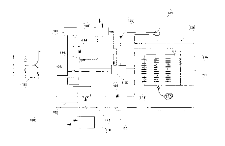
Referring to Figure 1, disclosed is an electric accumulator 106 for
selectively operating an
aircraft device 102. In other words an aircraft device 102 can be operated
intermittently or when
required by the electric accumulator 106. In an exemplary embodiment, the
aircraft device 102 is
an electrical or electro-mechanical load device which is at least partially
operable by electrical
energy. For example the aircraft device 102 may be landing gear device,
uplocks, an actuator for
landing gear, a braking system, a steering system, etc. The electric
accumulator 106 resides on an
electrical circuit 150. The electrical circuit 150 may be existing as part of
the aircraft circuitry,
for example. The aircraft device 102 is connected to the circuit 150 as shown
in Figure 1. The
aircraft device 102 may also be disconnected from the circuit 150, at which
time it will not
receive electrical energy through the circuit. An aircraft power distribution
controller 126 as well
as aircraft power 104 can also be connected to the circuit 150. Other
electronic components
known to a person of ordinary skill in the art may also be connected to the
circuit 150.
Although the invention will be herein described with reference to a single
ultra-capacitor 114 it
is understood that the preferred embodiment uses an array of ultra-capacitors
133, as shown and
described in detail below.
In one embodiment, shown in Figure 1, an input connection 110 is configured to
couple the ultra-
capacitor 114 to a power source 104. The power source 104 may include, for
example aircraft
4
CA 02688671 2015-12-18
power 104. The input connection 110 may include a charge control relay (as
shown in the
Figures). The aircraft power 104 may be connected through the circuit 150 to
each of the aircraft
device 102, an ultra-capacitor 114, and an ultra-capacitor charge circuit 112.
The aircraft power
distribution controller 126 may be connected through the circuit 150 to the
ultra-capacitor charge
circuit 112 and to the input connector 110, explained further below.
The electric accumulator 106 (shown by the dashed lines in Figure 1) includes
an ultra-capacitor
114 (or an ultra-capacitor array 133) for storing electrical energy. The ultra-
capacitor array 133
comprises individual ultra-capacitors 114. An output connector 129 is
configured to couple the
ultra-capacitor to the aircraft device 102. In the embodiment shown in the
figures the output
connector 129 is a relay 129, described in more detail below. The electrical
energy stored in the
ultra-capacitor 114 can later be directed along the circuit 150 through the
relay 129 to the aircraft
device 102 in order to power the aircraft device 102.
Operating voltage of the electric accumulator 106 can be increased by
connecting a number of
ultra capacitors 114 in series to form an ultra-capacitor array 133. For
example, typical aircraft
electrical systems operate at 28 V (dc). Since commercially available ultra-
capacitors 114 are
only capable of 2 to 3 V (dc) potential, 12 capacitors may need to be
connected in series to attain
the aircraft electrical system operating voltage. However, this may increase
the resistance of the
ultra-capacitor array 133 resulting in reduced maximum power output. Power
output as well as
additional energy storage capability can be increased by placing ultra-
capacitors 114 in parallel.
The number of parallel rows and the capacitance of each individual ultra-
capacitor 114 may be
determined based on the load characteristics of the aircraft device 102 being
operated. These
characteristics may include, for example, power requirements, operating
voltage range or
duration of use.
It is known in the art that a capacitor is an electronic device that can store
electrical charge. The
charge is stored Q in Coulombs is related to the capacitance C in Farads and
the voltage V across
the capacitor in Volts by the equation Q = CV. A super- or ultra-capacitor
array as referred to
herein, is a capacitor array with sufficient energy storage and power delivery
capability to
operate electro-mechanical and/or at least partially electronic aircraft
components, including but
5
CA 02688671 2009-12-15
not limited to components for propulsion, flight controls, landing gear and
braking systems.
As is known in the art, ultra-capacitors may use different materials,
geometric structures, and
manufacturing techniques such as porous carbon electric double layer
capacitor. A porous carbon
electric double layer capacitor consists of activated charcoal powder that
forms a porous carbon
structure to store the electric charge via ions of the electrolyte system
(typically acetonitrile (AN)
and tetraethylammonium tetrafluoroborate (TEATFB)). This type of capacitor
relies on
molecules in the electrolyte to act as the dielectric barrier using the
Hemholz double layer effect.
Since the dielectric strength of these molecules is relatively low, the
voltage potential is limited
to between 2 and 3 volts. Further, the use of a liquid electrolyte may limit
the operational range
of the ultra-capacitor 114 since the above mentioned electrolyte can become
more viscous at low
temperatures and freeze at temperature below -40 degrees Celsius. Lower
operating temperatures
may be achieved by adding other co-solvents to the electrolyte.
There are a number of emerging technologies that may improve upon the existing
electric double
layer ultra-capacitor. For example, the activated carbon powder may be
replaced with vertically
aligned carbon-nano tubes created using vapour deposition techniques. This
technology could
greatly reduce the internal resistance and increase surface area per unit
volume resulting in both
higher power output and increased energy storage capacity.
There are also emerging ultra-capacitor technologies that could exceed the
capabilities of the
electric double layer ultra-capacitor and eventually displace it. For example,
one technology
proposes using nano-manufacturing techniques on an aluminum substrate and
atomic layer
deposition to create billions of "electrostatic capacitors" per square
centimetre on the substrate.
Anodizing of the aluminum opens up nano ¨ pores with an aluminum oxide surface
and
subsequent thin layers of titanium nitride and aluminum oxide layers are
deposited to create and
connect the nano-capacitors into a vast array on a single substrate. The high
dielectric strength of
aluminum oxide permits higher operating voltages and since the device is solid
state, the
operational temperature range may be greatly expanded over the "porous carbon
electric double
layer capacitor". This technology could be readily utilized in the electric
aircraft accumulator
106, described herein, and function outside the pressurized areas of the
aircraft fuselage and in
6
CA 02688671 2015-12-18
space based applications.
It is recognized that the "aircraft electric accumulator" could utilize any of
the above capacitor
technologies as well as similar capacitor technologies developed now or in the
future.
An input connector 110 (a charge control relay for example) is configured to
couple the ultra-
capacitor 114 to a power source to allow the ultra-capacitor 114 to receive
electrical energy. For
example, the input connector 110 may close to allow electricity to flow from
the aircraft power
104 through the input connector 110 into ultra-capacitor 114 via the circuit
150 and via the ultra-
capacitor charge circuit 112. By way of further example, the input connector
110 may open to
restrict electricity from flowing to the ultra-capacitor 114 via the circuit
150 and the ultra-
capacitor charge circuit 112. In other words the input connector 110 is
configured to be
connected to the power source, thus allowing electrical energy to flow into
the ultra-capacitor
114, when power is required and disconnected when power is no longer required.
An output connector 129 is configured to couple the ultra-capacitor 114 to the
aircraft device
102. The output connector 129 may, for example, be a relay 129. For example,
the relay 129 may
be closed thus allowing electricity to flow from the ultra-capacitor 114 to
the aircraft device 102.
Similarly, the relay may be open thus restricting electricity from flowing
from the ultra-capacitor
114 to the aircraft device 102. In other words the output connector 129 is
configured to be
connected to (and allow electricity to flow to) the aircraft device 102 when
power is required,
such as for operating an aircraft device, and disconnected when power is no
longer required.
However, in the preferred embodiment the output connection remains connected
to the aircraft
device 102, both when power is required by the aircraft device 102 and when it
is not.
Referring to Figure 1, an accumulator input isolation diode 128 is operatively
connected to the
ultra-capacitor 114 for blocking electric current from flowing out of the
ultra-capacitor 114 and
into the aircraft power source 104. Electrical energy can flow from the
aircraft electrical supply
104 along the circuit 150 through the accumulator input isolation diode 128
which also resides
on the circuit 150. The accumulator input isolation diode 128 can, for
example, be any type of
diode suitable for use in the circuit 150 as described herein. On the output
side of the diode 128,
7
CA 02688671 2015-12-18
on the circuit 150, resides an input connector 110 for controlling the flow of
electricity along the
circuit 150. The accumulator input isolation diode 128 prevents electricity
from flowing back
towards the aircraft power source along the circuit 150 from the electric
accumulator 106 when
the input connector 110 is closed. When the input connector 110 is open,
electricity is prevented
from flowing along the circuit 150. Figure 1 shows the input connector 110 as
being open and
Figure 2 shows the input connector 110 as being closed. The input connector
110 is preferably a
charge control solid-state relay and is controlled by the aircraft power
distribution controller 126.
Additionally, the aircraft power distribution controller 126 can receive and
transmit information
over the aircraft data bus (not shown) to communicate with other aircraft
systems and the main
aircraft controller. The data bus may, for example, be a dual channel ARNIC
429 bus for
commercial aircraft. In an alternative embodiment, the aircraft power
distribution controller 126
transmit or communicate information via discreet signals. The discreet signals
may, for example,
be transmitted using hard wiring to other controllers or devices.
Referring still to Figure 1, the aircraft power distribution controller 126
can regulate or control
the amount of electrical power that the ultra-capacitor charge circuit 112
uses or consumes from
the aircraft power supply 104. Thus, if power demand is high from other
aircraft systems, the
aircraft power distribution controller 126 can reduce the amount of electrical
power flowing to
the ultra-capacitor charge circuit 112. Additionally, the aircraft power
distribution controller 126
can totally isolate the electric accumulator 106 from the aircraft power
supply 104 by switching
input connector 110 to the open position so that the electric accumulator 106
consumes or uses
none of the aircraft power supply 104.
The aircraft power distribution controller 126 also resides on the circuit 150
and is operatively
connected to the input connector 110. In other words the aircraft power
distribution controller
126 can open and close the input connector 110, and thereby control the energy
flow and
distribution along the circuit 150, and in particular, into and out of the
electric accumulator 106.
The aircraft power distribution controller 126 may, for example, determine
when the electric
accumulator 106 may be charged. For example, sensors (not shown) on the
8
CA 02688671 2015-12-18
aircraft may detect that the electrical demand for the aircraft generally is
low. The aircraft power
distribution controller 126 may then determine that it is therefore an
appropriate time to charge
the electric accumulator 106 using excess electrical energy from the
aircraft's general electrical
supply 104 for example. To do so the aircraft power distribution controller
126 closes the input
connector 110 to allow electrical energy to flow into the ultra-capacitors
from the power source
(which in this example is the aircraft's electrical supply).
The aircraft power distribution controller 126 may, for example, be automated
to automatically
open and close the input connector 110 when appropriate (e.g. when the ultra-
capacitor array 133
has capacity and when adequate electrical energy can be redirected from the
power source).
Alternatively, the input connector 110 may remain closed in order to maintain
full charge levels
in the ultra-capacitor 114.
The electric aircraft accumulator 106 includes an ultra-capacitor charge
circuit 112. The ultra-
capacitor charge circuit 112 can for example be a single resistor or a more
complex arrangement
consisting of a constant-current power supply or other controlled charging
circuit that would be
known to a person of ordinary skill in the art. The ultra-capacitor charge
circuit 112 is connected
to the aircraft power supply 104 via the circuit 150.
The circuit 150 may be fabricated out of wire or other suitable conductive
material.
The ultra-capacitors 114 may use carbon foam structure to increase the surface
area available for
storage of electrical charge, as would be familiar to a person of ordinary
skill in the art.
Individual capacitors may have a capacitance in the range of 3000 Farads with
11000 Joules of
energy storage, 7590 watts of maximum power output with a mass of 0.55 kg, for
example.
When electrical energy flows into the ultra-capacitors 114, the ultra-
capacitors 114 store
electrical energy (i.e. charge) for later use virtually instantaneously with
no detrimental effects.
Ultra-capacitors 114 operate at relatively low voltages (for example 2.5
volts) but, as described
below, can be arrayed in series to increase the voltage and arrayed in
parallel to increase the
power output.
9
CA 02688671 2009-12-15
. ,
As stated above, the electric accumulator 106 may comprise a plurality of
ultra-capacitors 114 to
increase the energy storage capacity and obtain the desired electrical
characteristics. For
example, three parallel columns of twelve series connected ultra-capacitors
114 may be
connected in an array on the circuit 150 as shown in Figure 1. This forms an
ultra-capacitor array
133, shown in Figure 3, containing thirty six ultra-capacitors 114. Ultra-
capacitors 114 are
arrayed in series on the circuit 150 to increase the voltage and in parallel
to increase the power
output capability of the electric accumulator 106.
In an alternative embodiment the power source is an external power supply (not
shown). The
ultra-capacitor 114 receives electrical energy through, and is thereby charged
through, an
external receptacle 124. The external receptacle 124 is a receiver into which
the external power
supply can be operatively connected. When operatively connected to the
external receptacle 124,
electrical energy can flow from the external power supply to the ultra-
capacitor 114. The ultra-
capacitor 114 stores the electrical energy for later use or discharge.
As shown in Figure 1, electrical power entering through the external
receptacle 124 is monitored
and controlled by the ultra-capacitor charge circuit 112.
The external power supply can be temporarily operatively connected to the
external receptacle
124. The ultra-capacitor 114 will only receive and store electrical power for
the duration of time
that the external power supply is operatively connected to the external
receptacle 124, and
electrical energy is flowing from the external power supply through the
external receptacle 124
to the ultra-capacitor 114.
In another embodiment, the electrical power for charging the electric aircraft
accumulator may
come from a second aircraft power supply.
In another embodiment, a second power supply is operatively connected to the
electric
accumulator 106 (e.g. via the circuit 150) in order to supply electrical
energy to the ultra-
capacitors 114 in the electric accumulator 106. Each of the power supply
sources may be
independently operated by the aircraft power distribution controller 126 (as
described below) and
may therefore independently provide electricity to the electric accumulator
106. It is recognized
CA 02688671 2009-12-15
that there may, similarly, be additional power supplies connected to the
electric accumulator 106
via the circuit 150.
A maintenance discharge resistor 116 and maintenance discharge switch 118
reside on the circuit
150 and may be used in order to discharge the electric accumulator 106 by
dissipating stored
electrical energy from the ultra-capacitor 114.
In more detail, the maintenance discharge switch 118 can be in one of two
position, "arm" or
"disarm". When in the arm position (as shown in Figure 1), the circuit 150 is
connected to the
ultra-capacitor 114 thereby allowing electricity to flow to the ultra-
capacitor 114. When in the
disarm position (not shown) the ultra-capacitor 114 is fully disconnected from
the charging
circuit 150 so that electricity cannot flow between the circuit and the ultra-
capacitor 114. In the
disarm position the maintenance discharge resistor 116 dissipates electricity
from the ultra-
capacitor 114. This may provide additional safety for example.
Optionally a back flow prevention diode 120 can be included in the circuit 150
on the output side
of the external receptacle 124. The back flow prevention diode 120 prevents
accidental discharge
through the external receptacle 124. Additionally the back flow prevention
diode 120 prevents
reverse polarity charging.
An accumulator output isolation diode 108 resides on the output portion of the
electric
accumulator 106. The accumulator output isolation diode 108 thereby prevents
the electrical
flow from the output side of the electric accumulator 106 from flowing back
into the aircraft
electrical system.
Similarly a back flow prevention diode 122 resides on the output portion of
the electric
accumulator 106. The back flow prevention diode 122 prevents flow from the
aircraft electrical
system from flowing into the output side of the electrical accumulator 106.
The fabrication and structure of diodes are familiar to those of ordinary
skill in the relevant art.
Similarly, the function of the diodes in the presently disclosed invention
will be understood to
those skilled in the art. For example, the diode could be a typical p-n semi-
conductor junction
11
1
CA 02688671 2009-12-15
diode commonly available for power applications (such as rectifiers) or a
specialized semi-
conductor diode to improve efficiency. One alternative may be the Super
Barrier diode which
has similar surge-handling capability and low reverse leakage current of a
normal p-n junction
diode but lower forward voltage drop.
Referring to Figure 3, the ultra-capacitors 114 may be in a series-parallel
array. Ultra-capacitors
114 may only be capable of a voltage potential of 2 to 3 volts. Having the
ultra-capacitors 114 in
series may a achieve a 28 volt working potential.
Figure 3 shows the ultra-capacitor array 133 in isolation. There are three
parallel columns of
ultra-capacitors 114 with each column having a series of twelve ultra-
capacitors 114. Additional
parallel columns of ultra-capacitors 114 may be added to the circuit 150 to
increase the power
output capability. The number of series connected ultra-capacitors 114 in the
columns can be
increased to increase the working voltage potential. Such properties of ultra-
capacitors arrays are
known to those skilled in the art.
The aircraft device 102 may be an electrical device or an electro-mechanical
device. For
example, the aircraft device 102 may be a landing gear device such as an
actuator for controlling
the descent and ascent of the landing gear; the aircraft device 102 may be an
uplock for securing
the landing gear in the ascended position; the aircraft device 102 may be a
steering system for
the aircraft or an electro-mechanical component of a steering system; or the
aircraft device 102
may be a braking system of an aircraft or an electro-mechanical component of a
braking system.
The aircraft device 102 may be other electro-mechanical or electrically
operated devices familiar
to a person of ordinary skill in the art. The aircraft device 102 may, for
example, be any
momentary-load device used on an aircraft.
In an alternative embodiment, shown in Figure 4 two aircraft devices 102 are
operatively
attached to the circuit 150. Each aircraft device 102 is attached in parallel
on the circuit 150.
Each of the aircraft devices 102 is operatively connected to the electric
accumulator 106 via the
circuit 150. The ultra-capacitor 114 of the electric accumulator 106 provides
stored electrical
energy to each of the two aircraft devices 102 for powering the aircraft
devices 102.
12
,
CA 02688671 2015-12-18
It is recognized that additional aircraft devices 102 may be similarly
connected to a single
electric accumulator 106 in a similar manner as in the above described circuit
150.
The sub-system controller 130 is operatively connected to each of the two
aircraft devices 102 so
that the sub-system controller 130 independently controls electricity
distribution to the two
aircraft devices 102.
The aircraft device 102 may be configured to connect to or disconnect from the
circuit 150 by a
relay 129, as described above, that in turn is operated by a sub-system-
controller 130. This sub-
system-controller 130 is responsible for control of a particular aircraft sub-
system (e.g. the
landing gear system). This sub-system-controller 130 is also connected to the
aircraft data bus
and can communicate to other system controllers and the aircraft central
controller. Thus, central
logic or software built into the aircraft central controller can receive data
regarding charge status
of the electric accumulator 106 from the aircraft power distribution
controller 126 and send a
signal to the sub-system-controller 130 indicating that sufficient power is
available to operate the
aircraft device 102.
The aircraft power distribution controller 126 may contain a computer
processor (CPU) and
communicate (send and receive data) with the aircraft central controller
(computer), other sub-
system controllers such as sub-system controller 130, and the ultra-capacitor
charge control
circuit 112 via a data bus (such as ARNIC 429) or hard wiring. The aircraft
power distribution
controller 126 may also contain memory. Memory may be programmed with
instructions,
executable by the processor based on input data received through the data bus
or hard wiring.
Upon executing the instructions, the processor (CPU) controls and instructs
the aircraft power
distribution controller 126 to operate the input connector 110 in order to
allow electrical energy
to flow into the electric accumulator 106 to charge the ultra-capacitor 114.
Similarly, instructions
(i.e. computer code) may be stored in memory such that the instructions are
executed by the
processor in order to provide an output signal to the ultra-capacitor charge
control circuit 112 to
control the flow rate of electricity to the ultra-capacitors 114.
13
CA 02688671 2009-12-15
The aircraft power distribution controller 126 may, additionally, receive as
input the accumulator
charge status indicating the level of electrical energy present in the
electric accumulator 106. In
one embodiment, the processor in the aircraft power distribution controller
126 receives the
accumulator charge status from charge control circuit 112 and automatically
(according to
instructions stored on memory) operates the charge control relay 110 in order
to provide more
electrical energy to the ultra-capacitor 114 in the electric accumulator 106.
The operation of the
charge control relay 110 may be controlled by an output signal sent from the
aircraft distribution
controller to the charge control relay 110. For example, if the accumulator
charge status indicates
that there is capacity for further electrical energy in the ultra-capacitor
114 then the aircraft
power distribution controller 126 may send an output signal, also referred to
as the accumulator
charge command, to the charge control relay 110 so that the charge control
relay closes to allow
electrical energy to flow from the power source to the ultra-capacitor 114.
Further, the processor
(CPU) in the aircraft distribution controller 126, may send an output signal
via the data bus (such
as ARNIC 429) or hard wiring to other sub-system controllers such as 130 or
the aircraft central
controller (computer) indicating the accumulator charge status.
A user interface (for example a switch controlling the landing gear ascent/
descent) may be
connected to a processor (CPU) in the sub-system controller 130. The user
interface may allow a
user to enter a command that will execute certain stored instructions on the
processor. Such
instructions may be stored or programmed into memory. When acceptable input
signals are
received, for example an acceptable accumulator charge status signal is
received from aircraft
distribution controller 126, instructions are executed by the processor (CPU)
in sub-system
controller 130 to close the device on/off relay 129 allowing the aircraft
device 102 to receive
electrical energy from the electric accumulator 106 and operate. For example,
when the
processor executes certain instructions from memory as requested by a user
through the user
interface the aircraft power distribution controller 126 may direct electrical
energy from the
electric accumulator to the landing gear actuator (an example of an aircraft
device 102) so that
the landing gear descends.
In another embodiment, the accumulator output isolation diode 108 could be
eliminated to allow
the electric accumulator 106 output to feed directly into the aircraft power
system, thus providing
14
CA 02688671 2015-12-18
back-up power for the entire system.
The sub-system controller 130 may independently operate each of the aircraft
devices 102
attached to the circuit 150. In other words the sub-system controller 130 may
allow electrical
energy to flow from the electric accumulator 106 to one of the aircraft
devices 102 but not the
other aircraft devices 102, and vice versa.
It is recognized that the power provided by the ultra-capacitors 114 in the
electric accumulator
106 may be above the power delivery capability of the aircraft's normal power
supplies. This
allows for smaller and lighter aircraft generators since peak output power of
these generators can
be reduced using the electric accumulator 106. This also results in reduced
load on the aircraft
engines to power the generators. Since the electric accumulator 106 can be
located close to the
aircraft device 102, the aircraft electrical wiring between the generators and
the aircraft device
102 can be reduced in size due to the lower current flow requirements. The net
result may be
better aircraft performance and lower fuel consumption.
Using the herein disclosed electric accumulator 106, the aircraft delivery
system voltage can be
increased above the conventional 28 Voltage DC.
It is recognized that the electric accumulator 106 as disclosed could also be
used for emergency
power or power smoothing for example.
Figure 5 is a flow chart of a method of providing power to an aircraft device
102. At step 1002
an electric accumulator 106 (as described above) is provided. At step 1004 the
electric
accumulator 106 is connected or coupled to a power source. For example, the
input connector
110 may be closed to allow electricity to flow to the ultra-capacitor 114 via
the circuit 150. At
step 1006 electrical power is directed from the power source to the electric
accumulator 106. At
step 1008 the electric accumulator 106 is connected or coupled to an aircraft
device 102. For
example, the relay 129 may be closed.
The step 1008 of connecting the electric accumulator 106 to the aircraft
device 102 can be
undertaken before the step 1006 of directing power from a power source to the
electric
CA 02688671 2009-12-15
accumulator 106. Similarly the step 1008 of connecting the electric
accumulator 106 to the
aircraft device 102 can be undertaken before the step 1004 of connecting the
electric accumulator
106 to the power source. Finally, at step 1010, electric power is directed
from the electric
accumulator 106 to the aircraft device 102.
Preferably, the electric accumulator 106 is mounted near the aircraft device
102 in order to
increase the efficiency of the emergency power backup and load levelling
capabilities of the
electric accumulator 106. For example, if the aircraft device is an electric
brake or an electric
steering system, the electric accumulator 106 could be mounted on the landing
gear leg or in the
landing gear bay.
In an embodiment (shown in Figure 6) the accumulator output isolation diode
108 is replaced
with an active current limiting circuit 132. In such a design, the current
flow from the aircraft
power source 104 is limited to a set value with the remainder of the required
power for the
aircraft device 102 coming from the ultra-capacitors 114. This modification is
analogous to a
restrictive flow device in a hydraulic circuit. The aircraft device 102 may be
able to derive all of
its power from aircraft power source 104 during low load operation, however,
when high loads
are encountered by the aircraft device 102, the power will preferentially flow
from the electric
accumulator 106. This arrangement protects the aircraft power source 104 from
being overloaded
at peak power demand but still allows the aircraft device 102 to operate at
high power levels on
an intermittent basis.
A further alternative embodiment, which will now be described, is shown in
Figure 7. The
aircraft device 102 cannot receive any power directly from the aircraft power
source 104. This
may be beneficial when the aircraft device 102 has the characteristic of
operating at very high
power levels for short duration bursts. In such an application, the aircraft
power source 104 may
be incapable of operating the aircraft device 102 or adding any significant
power to aid in its
operation. Such aircraft devices 102 may, for example, include high power
linear motors or
lasers. The aircraft power source 104 is capable of slowly charging the
electric accumulator 106
until an acceptable level of energy is stored in the accumulator 106 for the
aircraft device 102 to
operate. Once the aircraft device 102 is operated and energy in the electric
accumulator 106 is
16
,
CA 02688671 2009-12-15
depleted, the aircraft power source 104 can slowly charge the accumulator 106
once again.
The ultra-capacitors 114 preferably operate in areas where the temperatures
range from ¨40
degrees Celsius and 70 degrees Celsius, such as in the pressurized areas of
the aircraft.
In an embodiment, using the porous carbon electric double layer capacitor, by
adding co-solvents
to the electrolyte to improve low temperature viscosity and lower the freezing
point. By lowering
the operational temperature, they could the capacitors could potentially be
used in unpressurized
areas of the aircraft where operational temperature requirements are typically
¨54 degrees
Celsius. In such an embodiment the electric accumulator 106 could be located
closer to certain
aircraft devices 102 such as landing gear.
Although specific embodiments of the invention have been described herein, it
will be
understood by those skilled in the art that variations may be made thereto
without departing from
the spirit of the invention or the scope of the appended claims.
17