Language selection

Search

Patent 2688672 Summary

Third-party information liability

Some of the information on this Web page has been provided by external sources. The Government of Canada is not responsible for the accuracy, reliability or currency of the information supplied by external sources. Users wishing to rely upon this information should consult directly with the source of the information. Content provided by external sources is not subject to official languages, privacy and accessibility requirements.

Claims and Abstract availability

Any discrepancies in the text and image of the Claims and Abstract are due to differing posting times. Text of the Claims and Abstract are posted:

  • At the time the application is open to public inspection;
  • At the time of issue of the patent (grant).
(12) Patent: (11) CA 2688672
(54) English Title: OUTER PIN SEAL
(54) French Title: JOINT D'ETANCHEITE DE TIGE EXTERNE
Status: Expired and beyond the Period of Reversal
Bibliographic Data
(51) International Patent Classification (IPC):
  • F16C 33/74 (2006.01)
  • F16J 15/54 (2006.01)
(72) Inventors :
  • KLOUSIA, TIMOTHY ALLEN (United States of America)
  • STENDER, MARK WAYNE (United States of America)
  • BANOWETZ, MATTHEW EDWARD (United States of America)
  • YOUNG, ORENA DEE (United States of America)
  • OLSEN, JEFFREY FRANK (United States of America)
(73) Owners :
  • DEERE & COMPANY
(71) Applicants :
  • DEERE & COMPANY (United States of America)
(74) Agent: BORDEN LADNER GERVAIS LLP
(74) Associate agent:
(45) Issued: 2016-08-23
(86) PCT Filing Date: 2008-04-25
(87) Open to Public Inspection: 2009-01-15
Examination requested: 2013-04-24
Availability of licence: N/A
Dedicated to the Public: N/A
(25) Language of filing: English

Patent Cooperation Treaty (PCT): Yes
(86) PCT Filing Number: PCT/US2008/005411
(87) International Publication Number: US2008005411
(85) National Entry: 2009-10-09

(30) Application Priority Data:
Application No. Country/Territory Date
60/914,480 (United States of America) 2007-04-27

Abstracts

English Abstract


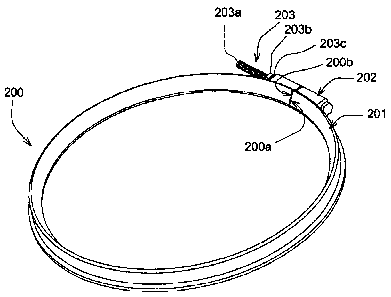
A seal (200) of substantially wedge shaped cross section self adjusts and
seals pivot joints (100) over a range of gap
widths to be sealed.


French Abstract

La présente invention concerne un joint (200) présentant une section transversale sensiblement cunéiforme à réglage automatique et étanchéifiant des articulations à pivot (100) sur une plage de largeur d'espace destinées à être étanchéifiées.

Claims

Note: Claims are shown in the official language in which they were submitted.


6
CLAIMS:
1. A seal for a pivot joint, the pivot joint including a pivot pin and a
bushing, the pivot joint
rotationally connecting a first member and a second member,
the first member having a longitudinal axis, a substantially conical external
surface, and a
substantially cylindrical external surface adjacent the substantially conical
external surface, the
substantially conical external surface having a cross section that is
substantially circular on a first
plane orthogonal to the longitudinal axis,
the second member having a circular external surface that is substantially
flat and
substantially orthogonal to the longitudinal axis,
a gap being defined axially between the substantially conical external surface
of the first
member and the circular external surface of the second member, and the gap
being defined
radially inward of the substantially cylindrical external surface,
the seal comprising:
a body defining a circle in a second plane orthogonal to the longitudinal
axis, the body
having a cross sectional shape generally conforming to that of a triangle,
a first outer diameter of the body formed by a first corner of the triangle,
a second outer diameter of the body formed by a second corner of the triangle,
the
second outer diameter being greater than the first outer diameter, a lip at
the second corner,
an inner diameter of the body formed by a third corner of the triangle, a
first seal
surface extending between the third corner and the first corner, the lip
including a second seal
surface,
an outer surface extending between the first corner and the second corner,
a majority of the body of the seal being positioned in the gap, with the lip
extending from
the outer surface radially outwardly away from the substantially cylindrical
external surface of
the first member.
2. The seal of claim 1, wherein the seal is connected over the axial gap
between the
substantially conical external surface and the circular external surface such
that the gap is sealed,

7
the seal fitting around a circumference of the substantially conical external
surface of the first
member.
3. The seal of claim 2, wherein the first seal surface contacts the
substantially conical
external surface.
4. The seal of claim 3, wherein the lip contacts the circular external
surface.
5. A method of using a seal to seal a pivot joint, the pivot joint
including a pivot pin and a
bushing, the pivot joint rotationally connecting a first member and a second
member,
the first member having a longitudinal axis, a substantially conical external
surface, and a
substantially cylindrical external surface adjacent the substantially conical
external surface, the
substantially conical external surface having a cross section that is
substantially circular about a
first plane orthogonal to the longitudinal axis,
the second member having a circular external surface that is substantially
flat and
substantially orthogonal to the longitudinal axis,
a gap being defined axially between the substantially conical external surface
of the first
member and the circular external surface of the second member, and the gap
being defined
radially inward of the substantially cylindrical external surface,
the seal including:
a seal body forming a circular construct, the seal body having a cross
sectional shape
generally conforming to that of a triangle, respective outer diameters of the
circular construct
defining circles orthogonal to the longitudinal axis and formed by a first
corner and a second
corner of the triangle, a lip at the second corner, an inner diameter of the
circle formed by a third
corner of the triangle, a first seal surface extending between the third
corner and the first corner,
a second seal surface extending between the third corner and the second
corner, and
a second portion along an arc of the circle and positioned along the outer
diameters, the
second portion having the effect of thickening the seal along the arc, a
length of the second
portion along the arc being greater than a width of the first portion,
the method comprising:

8
placing the seal of cross-sectional triangular shape across the gap between
the first
external surface and the circular external surface such that the first
external surface contacts the
first seal surface and the circular external surface contacts the second
corner and such that a
majority of the seal body is positioned in the gap.
6. The method of claim 5, wherein an outer surface of the seal extends
between the first and
second corners of the triangle and is substantially parallel to the
longitudinal axis.
7. The method of claim 5, wherein an outer surface of the seal is
substantially parallel to the
substantially cylindrical external surface.
8. The seal of claim 1, wherein the outer surface of the seal is
substantially parallel to the
longitudinal axis.
9. The seal of claim 1, wherein the outer surface of the seal is
substantially parallel to the
substantially cylindrical external surface of the first member.
10. The seal of claim 1, further comprising:
a portion along an arc of the circle and positioned along the outer diameter,
the portion
having the effect of thickening the seal along the arc, the portion and the
body being integral, the
portion and the body being split in a plane parallel to the longitudinal axis
such that the body has
a first end and a second end and the portion has a first end and a second end,
a length of the
portion along the arc being greater than a width of the body; and
a fastener for connecting the first end of the body and the second end of the
body and for
connecting the first end of the portion and the second end of the portion.
11. The seal of claim 1, wherein the lip is adapted to flex to maintain a
sealing of the pivot
joint during dimensional variations of the gap of the pivot joint.

9
12. A seal for a pivot joint, the pivot joint rotationally connecting a
first member and a
second member,
the first member having a longitudinal axis and a substantially conical
external surface,
the substantially conical external surface having a cross section that is
substantially circular on a
first plane orthogonal to the longitudinal axis,
the second member having a second external surface that is substantially
orthogonal to
the longitudinal axis,
the seal comprising:
a body forming a circle in a second plane orthogonal to the longitudinal axis,
the body
having a cross sectional shape including three corners,
a first outer diameter of the body formed by a first corner,
a second outer diameter of the body formed by a second corner, the second
outer
diameter being greater than the first outer diameter, a lip at the second
corner,
an inner diameter of the body formed by a third corner, a first seal surface
extending between the third corner and the first corner,
the lip including a second seal surface, an outer surface of the body
extending
between the first corner and the lip, the outer surface and the lip
cooperating to form an obtuse
angle.
13. The seal of claim 12, wherein the lip includes a first lip surface and
a second lip surface,
an angle between the first lip surface and the second lip surface being
greater than 180 degrees.
14. The seal of claim 13, wherein the second seal surface extends from the
second lip surface
of the lip.
15. The seal of claim 13, wherein the outer surface of the body extends
from the first corner
to the first lip surface of the lip, and the outer surface and the first lip
surface form the obtuse
angle.

10
16. The seal of claim 12, further including an inner surface extending
between the third
corner and the second corner, the second seal surface of the lip forming a
portion of the inner
surface.
17. The seal of claim 12, wherein at least one corner of the body is blunt.
18. The seal of claim 12, wherein the first seal surface has an arced
profile.
19. The seal of claim 18, wherein the first seal surface is concave.
20. The seal of claim 12, wherein the outer surface is flat.
21. The seal of claim 20, wherein the outer surface is parallel to the
longitudinal axis.
22. The seal of claim 12, wherein the seal is positioned in a gap defined
axially between the
substantially conical external surface and the second external surface, the
first seal surface
contacts the substantially conical external surface, and the second seal
surface of the lip contacts
the second external surface.
23. The seal of claim 1, wherein the lip defines a blunt tip at the second
corner.

Description

Note: Descriptions are shown in the official language in which they were submitted.


CA 02688672 2009-10-09
WO 2009/008941 PCT/US2008/005411
OUTER PIN SEAL
Field of the Invention
The invention relates, generally, to seals for pivot joints used to look
patiently
connect mechanical parts and, more particularly, to outer seals for pins and
bushings
that rotation only connect linkages and work tools on work vehicles.
Background of the Invention
Pivot joints used in the linkages of work vehicles such as, for example,
loader
backhoes and four wheel drive loaders include pins and bushings to allow
relative
rotation between connected parts. These pivot joints conventionally include
seals
between the pins and the bushings as barriers to debris. However, due to the
harsh
environments in which these vehicles are used, i.e., environments having
significant
amounts of dirt and debris, dirt and debris tend to get past these barriers
and cause
accelerated wear of the pivot joints.
Some manufacturers of work vehicles have sought to remedy the difficulties
outlined above by forming pre-barriers, i.e., a first line of defense against
debris, via
o-rings located between outer surfaces of the connected portions of linkages
and
work tools as shown in Figure 6 and 6A. however, this approach has led to at
least
the following two difficulties: (1) the o-rings are typically round, allowing
dirt and
debris to eventually work past the o-ring and into the space between the pins
and
bushings; and (2) the o-rings wear and their eventual replacement requires
disconnection of the rotationally connected parts, a substantial expense with
respect
to time and money.
Summary of the Invention
Described herein is a device and method for sealing a pivot joint against dirt
and debris that significantly reduces the difficulties addressed above. The
rotationally connected parts of the pivot joint include a first member having
an
external surface with a substantially circular cross section in a plane
perpendicular to
the longitudinal axis of the pin and a second member having an external
surface
substantially orthogonal to the longitudinal axis. The seal has a cross
section that is

CA 02688672 2009-10-09
WO 2009/008941 PCT/11S2008/005411
2
substantially wedge shaped. One corner of the wedge fits into a gap between
the
external cylindrical surface of the first member while the remaining corners
span the
gap between these surfaces. Each of the remaining corners spanning the gap may
include lips for completing the sealing function of the device and for
adjusting to
variations in the size of the gap. The seal is split, having a first end and a
second
end such that when the first and second ends are joined, it, i.e., the seal,
substantially forms a circle. At each end, the seal includes a connecting
portion. In
one embodiment, the connecting portion is on the seal's outer diameter and
integral
to the wedge. The first and second ends are generally joined via a connector
such
as, for example, a screw.
In practice, an accommodating portion of the external surface of the first
member is shaped to conform to the shape and angle of one side of the wedge.
Once the pivot joint is assembled, the seal is connected such that it fills a
gap
between the first member and the second member, where the one side of the
wedge
rides along the accommodating portion of the external surface of the first
member
and the lips of the seal ride along the external surface of the first member
and the
external surface of the second member. The seal is dimensioned to accommodate
a relatively wide range of gaps in tension.
Brief Description of the Drawin4s
The invention will be described in detail, with references to the following
figures, wherein:
Figure 1 is a view of a work vehicle in which the invention may be used;
Figure 2 is an oblique view of the front of the work vehicle illustrated in
Figure
1;
Figure 3 is an oblique view of the outer pin seal;
Figure 4 is another oblique view of the outer pin seal;
Figure 5 is a cross-sectional view of the joint illustrated in Figure 2
including
the outer pin seals;
Figure 6 is an oblique view of a conventional seal; and

CA 02688672 2009-10-09
WO 2009/008941 PCT/US2008/005411
3
Figure 6A is a cross-sectional view of Figure 6.
Description of the Illustrated Embodiment
Figure 1 illustrates a work vehicle in which the invention may be used. The
particular work vehicle illustrated is a four-wheel-drive loader 1 having a
rear portion
20, a front portion 30, a pivot 35 between the rear portion 20 in the front
portion 30, a
cab 24, of boom 33, a bucket 34, and a pivot joint 100 rotationally connecting
the
boom 33 and the bucket 34.
While the outer pin seal, i.e., the invention, will work on practically any
appropriately configured pivot joint, we will focus on the pivot joint 100 as
illustrated
in Figure 2 which employs a greaseless bushing 140. Figures 3 and 4 provide
oblique views of one embodiment of the invention which is first line defense
seal
200. Greaseless style bushings require many levels of sealing to ensure
bushing
life. In this particular case, the first line defense seal 200 is the exterior
seal at the
boom to bucket joint, i.e., the pivot joint 100, which is exposed to abrasive
chemicals
and extreme environmental/operating conditions and is required to keep debris
out of
the joint. Due to manufacturing limitations, dimensional variations between
parts
require the seal to be effective over gaps of considerable range. In this
particular
instance the seal needs to span gaps ranging from, for example, 1 mm to 12 mm.
Thus, the first line defense seal 200 is required to be adjustable, i.e., to
effectively
seal gaps of considerable range without failing into the pivot joint 100
during
operation. The first line defense seal 200 is also required to last the life
of the joint of
15,000 hours.
As illustrated in Figures 3 and 4, the first line defense seal 200 includes a
first
end 200a, a second end 200b, a first portion 201, a second portio,n 202 and a
connector 203. The first line defense seal 200 may be constructed of any
material of
suitabte flexibility and durability and may also contain self lubricating
materials such
as, for example molybdenum disulfide. The first line defense seal 200 be of
the
greaseless type as described above or may require the application of a
lubricant.

CA 02688672 2009-10-09
WO 2009/008941 PCT/US2008/005411
4
Figure 5 illustrates a cutaway view of one embodiment of the invention, i.e.,
first-line defense seal 200 as it is used to protect pivot joint 100 which
includes a first
member 110, a second member 120, a pin 130, and a bushing 140. As illustrated
in
Figures 3, 4, and 5, the first line defense seal 200 includes: a wedge shaped
first
portion 201 which includes lips 201 a and 201 b; a second portion 202; a first
end
200a; a second end 200b; and a connector 203, comprising a bolt 203a, a nut
203b,
and spacers 203c as required. As illustrated in Figure 5, exemplarily, a first
external
surface 110a of the first member 110 substantially conforms to a first portion
surface
201a of the first portion 201 of the first line defense seal 200. As
illustrated, lip 201a
contacts a second external surface 110b of the first member 110 and lip 201 b
seals
a circular external surface 120a of the second member 120. The circular
external
surface 120a is substantially flat and orthogonal to the longitudinal axis
130a of the
pin 130. The first extemal surface 110a is conical, i.e., at an angle that is
oblique to
the second external surface 110b. The second external surface 110b is
cylindrical in
shape.
In practice, the first line defense seal 200 is placed around the gap 100b as
shown in Figure 5 and connected via connector 203. Bolt 203a has an unthreaded
length that provides a length L sufficiently short to close the first line
defense seal
200 so as to provide an effective barrier to environmental contaminants and
sufficiently long to avoid unduly distorting the seal 200 when tightened down.
Once the first line defense seai 200 is tightened down, the first portion
surface
201c rides along the first external surface 110a while lip 201a contacts the
second
external surface 110b of the first member 110 and lip 201 b contacts the
circular
external surface 120a of the second member 120. The first line defense seal
200 is
always in some degree of tension in the sealed pivot joint 100. Due to the
shape of
the first member contacting surface 110a, which is, exemplarily, a chamfer in
this
case, the seal 200 will tend to seek a setting of the lease tension when it is
connected as it will self adjust along the first member contacting surface
110a as
dimensions of first member 110, the second member 120 and the gap 100b vary.
As
the gap 100b varies, the lips 201 a, 201 b aid in the self adjustment of the
seal 200 as

CA 02688672 2009-10-09
WO 2009/008941 PCT/US2008/005411
they tend to flex and relax as necessary to seal the gap 100b. As the outer
diameters of the first external surface 110a and the second external surface
110b
increase and decrease, the seal 200 tends to self adjust by positioning itself
down
and up along the first member contacting surface correspondingly.
5 Having described the illustrated embodiment, it will become apparent that
various modifications can be made without departing from the scope of the
invention
as defined in the accompanying claims.

Representative Drawing
A single figure which represents the drawing illustrating the invention.
Administrative Status

2024-08-01:As part of the Next Generation Patents (NGP) transition, the Canadian Patents Database (CPD) now contains a more detailed Event History, which replicates the Event Log of our new back-office solution.

Please note that "Inactive:" events refers to events no longer in use in our new back-office solution.

For a clearer understanding of the status of the application/patent presented on this page, the site Disclaimer , as well as the definitions for Patent , Event History , Maintenance Fee  and Payment History  should be consulted.

Event History

Description Date
Time Limit for Reversal Expired 2023-10-25
Letter Sent 2023-04-25
Letter Sent 2022-10-25
Letter Sent 2022-04-25
Inactive: COVID 19 - Deadline extended 2020-03-29
Common Representative Appointed 2019-10-30
Grant by Issuance 2016-08-23
Inactive: Cover page published 2016-08-22
Pre-grant 2016-06-27
Inactive: Final fee received 2016-06-27
Notice of Allowance is Issued 2016-05-17
Letter Sent 2016-05-17
Notice of Allowance is Issued 2016-05-17
Inactive: Q2 passed 2016-05-11
Inactive: Approved for allowance (AFA) 2016-05-11
Amendment Received - Voluntary Amendment 2016-02-18
Inactive: S.30(2) Rules - Examiner requisition 2015-08-20
Inactive: Report - No QC 2015-08-19
Amendment Received - Voluntary Amendment 2015-06-26
Inactive: S.30(2) Rules - Examiner requisition 2014-12-29
Inactive: Report - No QC 2014-12-10
Amendment Received - Voluntary Amendment 2014-07-28
Inactive: S.30(2) Rules - Examiner requisition 2014-01-28
Inactive: Report - No QC 2014-01-24
Letter Sent 2013-05-07
Request for Examination Requirements Determined Compliant 2013-04-24
All Requirements for Examination Determined Compliant 2013-04-24
Request for Examination Received 2013-04-24
Inactive: Correspondence - PCT 2012-01-23
Inactive: Delete abandonment 2010-07-22
Letter Sent 2010-05-10
Inactive: Office letter 2010-05-10
Letter Sent 2010-05-10
Deemed Abandoned - Failure to Respond to Notice Requiring a Translation 2010-04-14
Inactive: Compliance - PCT: Resp. Rec'd 2010-03-12
Inactive: Single transfer 2010-03-12
Inactive: Declaration of entitlement - PCT 2010-03-12
Inactive: Cover page published 2010-02-19
Inactive: IPC assigned 2010-01-26
Inactive: First IPC assigned 2010-01-26
Inactive: IPC assigned 2010-01-26
Inactive: Notice - National entry - No RFE 2010-01-14
Inactive: Incomplete PCT application letter 2010-01-14
Application Received - PCT 2010-01-14
National Entry Requirements Determined Compliant 2009-10-09
Application Published (Open to Public Inspection) 2009-01-15

Abandonment History

Abandonment Date Reason Reinstatement Date
2010-04-14

Maintenance Fee

The last payment was received on 2016-03-31

Note : If the full payment has not been received on or before the date indicated, a further fee may be required which may be one of the following

  • the reinstatement fee;
  • the late payment fee; or
  • additional fee to reverse deemed expiry.

Patent fees are adjusted on the 1st of January every year. The amounts above are the current amounts if received by December 31 of the current year.
Please refer to the CIPO Patent Fees web page to see all current fee amounts.

Owners on Record

Note: Records showing the ownership history in alphabetical order.

Current Owners on Record
DEERE & COMPANY
Past Owners on Record
JEFFREY FRANK OLSEN
MARK WAYNE STENDER
MATTHEW EDWARD BANOWETZ
ORENA DEE YOUNG
TIMOTHY ALLEN KLOUSIA
Past Owners that do not appear in the "Owners on Record" listing will appear in other documentation within the application.
Documents

To view selected files, please enter reCAPTCHA code :


To view images, click a link in the Document Description column (Temporarily unavailable). To download the documents, select one or more checkboxes in the first column and then click the "Download Selected in PDF format (Zip Archive)" or the "Download Selected as Single PDF" button.

List of published and non-published patent-specific documents on the CPD .

If you have any difficulty accessing content, you can call the Client Service Centre at 1-866-997-1936 or send them an e-mail at CIPO Client Service Centre.

({010=All Documents, 020=As Filed, 030=As Open to Public Inspection, 040=At Issuance, 050=Examination, 060=Incoming Correspondence, 070=Miscellaneous, 080=Outgoing Correspondence, 090=Payment})


Document
Description 
Date
(yyyy-mm-dd) 
Number of pages   Size of Image (KB) 
Description 2009-10-08 5 207
Abstract 2009-10-08 2 60
Claims 2009-10-08 3 98
Drawings 2009-10-08 6 91
Representative drawing 2010-01-25 1 10
Claims 2014-07-27 5 321
Claims 2015-06-25 4 155
Claims 2016-02-17 5 178
Representative drawing 2016-07-14 1 10
Reminder of maintenance fee due 2010-01-13 1 112
Notice of National Entry 2010-01-13 1 206
Courtesy - Certificate of registration (related document(s)) 2010-05-09 1 101
Reminder - Request for Examination 2012-12-30 1 126
Acknowledgement of Request for Examination 2013-05-06 1 190
Commissioner's Notice - Application Found Allowable 2016-05-16 1 163
Commissioner's Notice - Maintenance Fee for a Patent Not Paid 2022-06-05 1 551
Courtesy - Patent Term Deemed Expired 2022-12-05 1 546
Commissioner's Notice - Maintenance Fee for a Patent Not Paid 2023-06-05 1 540
Correspondence 2010-01-13 1 22
PCT 2009-10-08 1 48
Correspondence 2010-03-11 2 60
Correspondence 2010-05-09 1 21
Correspondence 2012-01-22 3 83
Amendment / response to report 2015-06-25 8 323
Examiner Requisition 2015-08-19 3 212
Amendment / response to report 2016-02-17 9 502
Final fee 2016-06-26 1 34