Note: Descriptions are shown in the official language in which they were submitted.
CA 02688713 2009-11-26
WO 2008/145652 PCT/EP2008/056487
- 1 -
HEAT EXCHANGER SHELL ASSEMBLY AND METHOD OF ASSEMBLING
Field of the Invention
The present invention relates to a heat exchanger
shell assembly and a method of assembling a heat
exchanger shell structure.
Background of the Invention
A shell-and-tube heat exchanger is an indirect heat
exchanger. Heat is transferred between a fluid passing
through the tubes of a tube bundle (the tube side)
extending in a heat exchanger shell, and a fluid passing
through the space outside the tubes (the shell side).
Details of shell-and-tube heat exchangers can for example
be found in Perry's Chemical Engineers' Handbook, 7th
edition, 1997, McGraw-Hill Inc., page 11-33 to 11-46.
Shell-and-tube heat exchangers can be distinguished
according to the number of passes for fluid in the shell
side and in the tube side. In each pass, the respective
fluid flows substantially along the entire length of the
heat exchanger, which is typically horizontally
elongated. In multiple shell passes, the fluid flow
meanders a plurality of times back and forth the length
of the shell.
The heat exchanger shell has inlet and outlet nozzles
for the shell-side fluid. For a single shell-side pass
heat exchanger, an inlet nozzle is typically arranged at
one end of the shell, in particular on top of the shell,
and an outlet nozzle is arranged at the opposite end, in
particular at the bottom. The same is true for an uneven
number of passes. In case of two shell-passes (or in fact
an even number), the inlet and outlet nozzles are
suitably arranged at the same end.
When retrofitting a heat exchanger such as for
modified use or improved performance, it can be desired
CA 02688713 2009-11-26
WO 2008/145652 PCT/EP2008/056487
- 2 -
to adapt the number of passes. For example, if a tube
bundle with transverse supports comprising expanded metal
baffles is to be installed, a higher number of shell-side
passes can be preferred for optimum performance. Expanded
metal is produced from sheet metal that is slit and
expanded. Expanded-metal baffles are for example known
from International patent applications with publication
Nos. WO 2003/067170, W02005/015107 and W02005/061982,
incorporated herein by reference, and turn out to have
significant advantages in practice, such as less fouling
tendency, lower pressure drop, and improved heat transfer
due to turbulence created in the shell fluid. In expanded
metal baffles spanning the cross-section of the available
shell pass, the flow of shell fluid is longitudinal. In a
conventional heat exchanger using segmental baffles, the
flow meanders even with one shell side pass along the
main flow path in the shell, so that the effective length
of the shell-side flow is longer than the longitudinal
extension of the shell. When expanded metal baffles are
used, it is preferred to use a higher number shell-side
passes to optimise the shell flow path length, and this
can particularly be done in view of the low pressure drop
caused by the expanded metal baffles.
A problem is encountered when the number of shell-
side passes is to change between even and uneven, since
then one of the nozzles is unsuitably located. In
principle, it can be envisaged to arrange an internal
flow path for shell-side fluid from one end of the shell
to the other. It is an object of the invention to provide
a heat exchanger shell arrangement that allows to modify
the number of shell-side passes.
Summary of the Invention
To this end the present invention provides a heat
exchanger shell arrangement comprising
an outer shell having a nozzle at its lower side;
CA 02688713 2009-11-26
WO 2008/145652 PCT/EP2008/056487
- 3 -
an inner shell member within the outer shell and forming
an intermediate space with the outer shell, the inner
shell member having an opening at its lower side;
wherein the arrangement further comprises a seal member
arranged to fit in the intermediate space, the seal
member providing a sealed passageway for fluid between
the opening and the nozzle.
By arranging an inner shell member, it is possible to
direct shell side fluid from one shell end to the other,
using the intermediate space. The inner shell space, in
which the actual heat exchange with a tube bundle is to
take place, needs to be sealed against the intermediate
space, otherwise shell side fluid could flow along a
shortcut route, lowering heat transfer efficiency. A seal
member between inner shell member and outer shell is
provided for this purpose. Preferably, the seal member is
a gravity seal member, wherein sealing force is provided
by the gravity force exerted on the seal member by the
inner shell member. In particular, the seal member is not
connected to at least one of the outer shell and the
inner shell member, preferably it is not connected to
both the outer shell and the inner shell member. This
allows particularly easy installation of the shell
arrangement, since the sealing member can be pushed into
the intermediate space after the inner shell member is
arranged in the outer shell, and sealing is simply
accomplished lowering the inner shell so that its weight,
suitably together with the weight of the tube bundle,
exerts the sealing force for the sealing member.
Moreover, by not connecting the inner and outer shells
via the seal member, different temperature expansion
between the outer shell and inner shell member can be
accommodated.
In a suitable embodiment, the seal member is a plate
having upper and lower surfaces that are arranged to
CA 02688713 2009-11-26
WO 2008/145652 PCT/EP2008/056487
- 4 -
conform to the outer shell and inner shell member
surrounding the nozzle and the opening, preferably
comprising a gasket at the upper and/or lower surface.
In a particular embodiment, the nozzle forms a first
nozzle of the outer shell and the opening forms a first
opening of the inner shell member, the outer shell
further comprises a second nozzle and the inner shell
member comprises a second opening, and the second nozzle
and the second opening are arranged to be fluid
communication via the intermediate space.
The invention further provides a method of assembling
a heat exchanger, comprising
providing an outer shell having a nozzle at its lower
side and an inner shell member having an opening;
sliding the inner shell member into the outer shell
to form an intermediate space with the outer shell and to
reach a position in which the opening is above the
nozzle;
arranging the inner shell member in a lifted position
in the outer shell;
sliding a seal member into the intermediate space,
the seal member providing a passageway for fluid between
the opening and the nozzle; and
lowering the inner shell member so that the gravity
force exerted on the seal member acts as sealing force.
The method is particularly useful for revamping a
heat exchanger, wherein the outer shell is maintained and
a new tube bundle is arranged within an inner shell
member.
Brief description of the Drawings
The invention will now be described in more detail
and with reference to the accompanying drawings, wherein
Figure 1 shows schematically heat exchanger with a
heat exchanger shell assembly according to the invention;
CA 02688713 2009-11-26
WO 2008/145652 PCT/EP2008/056487
- 5 -
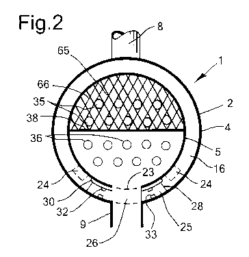
Figure 2 shows the heat exchanger of Figure 1 is
cross-section along line II-II;
Figure 3 shows schematically a top view of the seal
member 25 in Figures 1 and 2.
Where the same reference numerals are used in
different Figures, they refer to the same or similar
objects.
Detailed Description of the Invention
Reference is made to Figures 1-3 showing
schematically a heat exchanger 1 including a heat
exchanger shell assembly or structure 2 according to the
invention. The heat exchanger shell assembly 2 comprises
an outer shell 4 and an inner shell member 5. The outer
shell 4 has an inlet nozzle 8 (second nozzle) at its
upper side and an outlet nozzle 9 (first nozzle) at its
lower side. The inner shell member 5 extends
cylindrically between a tube sheet 12 and floating head
14, thereby forming an intermediate space 16 with the
outer shell. The inner shell member has an inlet opening
(second opening) 21 in the form of a plurality of holes
around its upper side near the end opposite to the inlet
nozzle 8, and an outlet opening 23 (first opening) at its
lower side at the same end. For handling during
installation, the inner shell member 5 is preferably
provided with longitudinal sliding bars 24 on which the
inner shell member can be slid into the outer shell 4.
A seal member 25 is placed in the intermediate
space 16, the seal member providing a sealed passageway
26 for fluid between the outlet opening 23 and the outlet
nozzle 9.
The seal member 25 is only very schematically shown
in Figure 1, and is best seen in Figures 2 and 3. Its
basic structure is formed of an arcuated plate 28
conforming to the outer shell and inner shell member. A
handle 31 serves for handling the seal member during
CA 02688713 2009-11-26
WO 2008/145652 PCT/EP2008/056487
- 6 -
installation. The inner shell member is provided with a
plate 30 that is welded around the outlet 23, to form a
contact surface for the seal member.
For optimum sealing the seal member is provided with
top and bottom gasket rings 32,33, suitably arranged in a
circular groove seating machined into plate 28 of the
seal member. A suitable gasket material is
polytetrafluoroethylene (PTFE) for temperature resistance
up to 250 degree C. Good results have been obtained with
100% expanded PTFE (e-PTFE), multidirectional orientated
fibre structure, type Gore-Tex Series 300. The
temperature range of this material is between -240 C and
+250 C, with allowable peak temperatures up to 315 C. A
PTFE tape of 3 mm thickness was used. For the sealing of
the floating head and baffle sealing tape with a
thickness 2 mm was used. Before placement of the gasket
rings, the seating was cleaned with alcohol and the
gasket was glued into the seating.
Thus, the seal member 25 is arranged to seal by
gravity. It can be introduced loosely into the
intermediate space 16 while the inner shell is lifted.
Sealing force is provided by the gravity force exerted on
the seal member by the inner shell member, and sealing is
achieved without the seal member being fastened to either
one of the shells 4,5. After installation of the seal
member, the inner shell member does not rest on the
sliding strips 24 in the vicinity of the outlet opening
23.
The inner shell member houses the tubes 35,36
extending from the tube sheet 12 to floating head 16, and
the tubes contribute to the weight pressing on the seal
member. The weight can for example be more than 1000 kg
such as 5000 kg. A longitudinal baffle 38 with an opening
39 serves to provide a two-pass configuration of the
shell side. For mechanically mounting the longitudinal
CA 02688713 2009-11-26
WO 2008/145652 PCT/EP2008/056487
- 7 -
baffle, the inner shell member can be constructed of
upper and lower half shells, between which the
longitudinal baffle is clamped.
Turning now to the tube side of the heat exchanger 1,
only few tubes 35,36 are shown for the sake of clarity.
The tube side of the heat exchanger 31 is indicated with
dots. In this embodiment the tube side has a two-tube-
pass arrangement. The tube side has an inlet 41 to a tube
inlet header 43. The tube inlet header is in fluid
communication with the lower part of the tube bundle,
tubes 36 which extend to the tube end sheet 44 connected
to the floating head 14 which in turn is in fluid
communication with the upper part of the tube bundle,
tubes 35 extending into the tube outlet header 47 where
the outlet 49 from the tube side is arranged. The inlet
and outlet tube heads 43,47 are separated by a horizontal
plate 51 extending horizontally along in the centre of
the outer shell 4 from the shell end to the tube sheet 12
in which the tubes are fixed. The tube sheet is secured
to the shell by flanges (not shown), through which the
inlet end of the shell can be opened for inserting or
removing the internals. Flanges through which the end
part of the shell can be removed are also arranged at the
rear end near floating head 14.
The tube end sheet 44 at the opposite end also fixes
the tubes, but unlike the tube sheet 12, the tube end
sheet 44 and the floating head 14 to which it is
connected, are not connected to the shell 34, i.e. the
end header is floating. This allows thermal expansion of
the tubes within the shell. Instead of an end header,
which receives and distributes all tube fluid, also
separate U-tubes could be applied.
The tubes are supported by a plurality of transverse
baffles 65. They can in particular be expanded metal
baffles, but rod baffles or other baffles can also be
CA 02688713 2009-11-26
WO 2008/145652 PCT/EP2008/056487
- 8 -
applied. In Figure 2, an expanded metal grid 66 is
illustrated supporting the tubes 35 in the upper half.
Only few tubes are shown extending and supported by
through the windows of the expanded metal structure.
Suitably the tubes 36 in the lower half are supported in
the same way.
Normal operation of the assembled heat exchanger 1
will now be discussed. When the heat exchanger is used in
a crude preheat train of a crude distilling unit, tube-
side fluid can be (cold) crude oil and shell-side fluid
can be (hot) long residue from the crude distillation
unit. For such an application with considerable fouling
risk, expanded metal baffles in the shell side are
advantageous because they suppress fouling. Tube-side
fluid is passed via inlet 41 and tube inlet header 43
along the tubes 36, and further via the floating head 14
to along the upper part of the tube bundle to outlet
header 47 and outlet 49. During that passage, it is
heated by exchanging heat with the shell side fluid.
Hot shell-side fluid is introduced via inlet nozzle 8
into the outer shell, where it flows along the
intermediate space towards the inlet 21 of the inner
shell member. This inlet is formed of a plurality of
holes spread around the upper part of the inner shell
member. In this way an optimum distribution of shell
fluid around the tubes 35 is achieved. The shell-side
fluid flows towards the tube sheet 12, turns via the
opening 39 and continues towards the outlet 23. From
outlet 23 it passes through the passageway 26 formed by
the seal member to the outlet nozzle 9, with a lower
temperature than at the inlet nozzle 8.
The lower half of the intermediate space (annulus)
between outer shell 4 and inner shell member 5 is filled
with non- or slow flowing shell fluid. This fluid will
adopt a temperature somewhere near the tube side inlet
CA 02688713 2009-11-26
WO 2008/145652 PCT/EP2008/056487
- 9 -
temperature. Since the seal member does not interconnect
outer shell 4 and inner shell member 5, they can
thermally expand differently in response to different
temperatures they will have in the course of operation.
Now a method of assembling the heat exchanger shell
structure 2 of Figure 1 will be discussed. First the
outer shell is provided, not including the end portions
of the tube inlet/outlet header and the floating head, so
that suitably both longitudinal ends are open. In the
case of a revamp, the outer shell of the original heat
exchanger is maintained, and new internals, typically
tube bundle and internal shell, are provided. The tube
sheets, inlet/outlet headers, floating head may need to
be modified or replaced. The inner shell member 5,
suitably including the tube bundle, is slid on the
sliding bars 24 into the outer shell until the opening 23
is directly above the outlet nozzle 9. Then the inner
shell member is lifted sufficiently so that the seal
member can be passed into the intermediate space between
the outlet opening 23 and the outlet nozzle 3. The inner
shell member is lowered, so that the gravity force
exerted on the seal member acts as sealing force. Then
the heat exchanger can be completed by attaching the end
parts with flanges.
If cleaning of the heat exchanger is required, it can
be disassembled in reverse order, cleaned, and assembled
again.