Note: Descriptions are shown in the official language in which they were submitted.
CA 02688840 2009-12-03
1
TITLE: ANTI-SKIDDING STRUCTURE OF AUTOMOBILE FOOT
MAT
(a) Technical Field of the Invention
The present invention generally relates to an anti-skidding structure of
automobile foot mat, which is particularly fit for anti-skidding purposes for
floors made of felts/rugs, flannelette, and loop cloth, wherein the foot mat
features touch-fastened anti-skidding without damage of the floor materials,
so
as to be suitable for automobile floor carpets or household carpets to be
treaded as a foot mat and providing anti-skidding effect.
(b) Description of the Prior Art
A conventional foot mat is often structured to form an anti-skidding
structure on a bottom thereof so that when it is laid on a regular carpet to
serve
as a floor mat, it provides the effect of anti-skidding. For example,
automobile floor carpets are generally divided as needle punched carpets and
tufted carpets. To maintain and clean the in-car carpets, a removable foot
mat is. often provided to position on an in-car carpet that is often
integrally
formed with the automobile floor at a location where a driver or passengers
may tread. Generally, the removable foot mats are arranged in a set
composed of four mats, which are respectively positioned on the floors in
front of the driver's seat, the front passenger's seat, and the back seat, in
order
CA 02688840 2009-12-03
2
to protect the expensive underside in-car carpet that is integrally formed in
the
automobile from being stained. A regular automobile foot mat is positioned
on the in-car carpet, but relative sliding often occurs between the foot mat
and
the in-car carpet due to the force of treading applied by the automobile
driver
or passengers. This may become dangerous when undesired sliding occurs
in the foot mat of the driver's seat, for such a sliding movement may bring
the
foot mat to such an undesired location where the mat hinders the operation of
for example a brake pedal by reducing the stroke of the brake pedal.
Improvement is certainly required for this problem.
Various anti-skidding structures of foot mats are known. For example, a
foot mat is provided with a plurality of projecting spikes at an undersurface
thereof so that when the foot mat is positioned on a carpet, the spikes
penetrate
into the material of the carpet to increase sliding resistance and friction
therebetween thereby realizing anti-skidding. However, this type of
anti-skidding structure formed of projecting spikes may easily cause damage
to the surface of the carpet, and in addition, such type of anti-skidding
structure does not provides good result of anti-skidding. Another known mat
anti-skidding structure comprises hardened anti-skidding beads that are mode
of non-woven fabric mounted to an undersurface of a mat. However, this
type of anti-skidding structure only works for effecting anti-skidding on
needle
CA 02688840 2009-12-03
3
punched carpets, but does not work for tufted carpets. Thus, in the
automobile industry, in order to realize effect anti-skidding between a foot
mat
and an in-car carpet, fixed positioning pillars are provided on the in-car
carpet,
while the foot mats form sockets at corresponding locations, whereby when
the foot mat are correctly positioned, the sockets are fit over and engage the
positioning pillars to securely fix the foot mats against undesired skidding.
This arrangement, however, largely increases the manufacturing costs and is
adverse for user replacing foot mats that may not be provided with sockets
exactly corresponding to the existing positioning pillars, leading to very low
chance of replacement of foot mat.
To solve the above problems, the present invention provides a unique
touch-fastened anti-skidding structure to be attached to an undersurface of a
foot mat. The anti-skidding material features easy processing in combining
to both planar foot mats and three-dimensional foot mats. Further, the
1.5 anti-skidding structure provided on the undersurface of the foot mat does
not
cause any damage or undesired napping on various materials, including
felts/rugs, flannelette, and loop cloth and can be securely held in position
without undesired skidding on the existing in-car carpets, thereby providing
highly effectively effect of touch-fastened anti-skidding.
CA 02688840 2009-12-03
4
Thus, the present invention aims to provide an effective anti-skidding
structure for an anti-skidding foot mat that is good for mass-production and
has a light weight, excellent air-permeable and cushioning effect, and a
simplified structure to realize anti-skidding for various materials, including
felts/rugs, flannelette, and loop cloth.
CA 02688840 2009-12-03
SUMMARY OF THE INVENTION
The primary objective of the present invention is to provide an
anti-skidding structure of an automobile foot mat, which is suitable for
various
types of carpets, including needle punched carpets and tufted carpets, for
5 increasing frictional force between an undersurface of the foot mat and an
in-car carpet to realize anti-skidding.
Another objective of the present invention is to provide an anti-skidding
structure of an automobile foot mat that does not cause damage or undesired
napping of a carpet and possesses the advantages of simple structure, easy
processability, low manufacturing cost, good durability, and excellent
adaptability, and provides soft tactility for foot contact.
To achieve the above objectives, the present invention provides an
anti-skidding structure of an automobile foot mat, which comprises an
upper-layer, surface layer material and a lower-layer skidding-resistant
anti-skidding material. The two layers are lapped and are bonded together
through molding operation. The surface layer can be made of foaming
substances, such as crosslinked polyethylene (XPE) foamed board,
polyethylene (PE), ethylene-vinyl acetate copolymer (EVA), and polyurethane
(PU) foamed board. The surface layer can be alternatively a carpet or a
board made of thermoplastic elastomer (TPE), anti-skidding thermoplastic
CA 02688840 2009-12-03
6
rubber (TPR), or polyvinylchloride (PVC). For a surface layer of the foot
mat made of a foaming substance, a top layer may be further added atop the
foaming substance and the top layer can be a carpet or a board made of TPE,
anti-skidding TPR, or PVC to improve the feeling of product quality. The
anti-skidding material of the lower layer comprises a plurality of minute
synthetic yarns that can induce an effect of touch fastening and skidding
resistance on any kinds of carpet and that can be separable from the carpets
without causing any damage to the carpets, whereby the foot mat, as a whole,
has high effect of anti-skidding.
The foot mat discussed above can be made as a planar mat, or it can be
made in a three-dimensional configuration having a central recess surrounded
by raised edge rims to facilitate subsequent cleaning operation of the
automobile in which the foot mat is placed.
For an in-car foot mat, the following characteristics are required:
(1) A finished foot mat must be light in weight in order to meet the need
for fuel saving and environmental protection.
(2) The foot mat must be effective in anti-skidding and does not cause
any damage to the material of an in-car carpet.
(3) The manufacturing cost must be low and since improving market
competitiveness by mass production will certainly lead to reduction of
CA 02688840 2009-12-03
7
manufacturing costs, the improvement of manufacturing process and the
selection of raw material must be exercised to both reduce sale price and
enhance functionality.
The foregoing objectives and summary provide only a brief introduction
to the present invention. To fully appreciate these and other objects of the
present invention as well as the invention itself, all of which will become
apparent to those skilled in the an, the following detailed description of the
invention and the claims should be read in conjunction with the accompanying
drawings. Throughout the specification and drawings identical reference
numerals refer to identical or similar parts.
Many other advantages and features of the present invention will become
manifest to those versed in the art upon making reference to the detailed
description and the accompanying sheets of drawings in which a preferred
structural embodiment incorporating the principles of the present invention is
shown by way of illustrative example.
CA 02688840 2009-12-03
8
BRIEF DESCRIPTION OF THE DRAWINGS
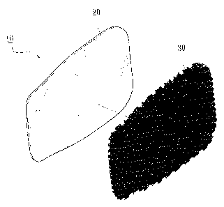
FIG 1 is an exploded view of an automobile foot mat in accordance with
a first embodiment of the present invention.
FIG 2 is a partial cross-sectional view of the automobile foot mat in
accordance with the first embodiment of the present invention.
FIG 3 is an exploded view of an automobile foot mat in accordance with
a second embodiment of the present invention.
FIG 4 is a partial cross-sectional view of the automobile foot mat in
accordance with the second embodiment of the present invention.
FIG 5 is a back side perspective view of an automobile foot mat
constructed in accordance with the present invention.
FIG 6 a back side perspective view of another automobile foot mat
constructed in accordance with the present invention.
FIG 7 is an enlarged view of a portion of a touch-fastening anti-skidding
material in accordance with the present invention.
FIG 8 is a schematic view showing a foundation layer and synthetic
yarns woven together in accordance with the present invention.
FIG 9 is a partial cross-sectional view of the touch-fastening
anti-skidding material in accordance with the present invention.
CA 02688840 2009-12-03
9
DETAILED DESCRIPTION OF THE PREFERRED EMBODIMENTS
The following descriptions are exemplary embodiments only, and are not
intended to limit the scope, applicability or configuration of the invention
in
any way. Rather, the following description provides a convenient illustration
for implementing exemplary embodiments of the invention. Various
changes to the described embodiments may be made in the function and
arrangement of the elements described without departing from the scope of the
invention as set forth in the appended claims.
With reference to the drawings and in particular to FIGS. 1 and 2, the
present invention provides afoot mat, generally designated at 10. The foot
mat 10 is composed of a surface layer 20 that is located at the upper side and
an anti-skidding layer 30 that is set at the bottom. The surface layer 20 can
be solely made of a foaming substance, a carpet, thermoplastic elastomer
(TPE), anti-skidding thermoplastic rubber (TPR), or polyvinylchloride (PVC).
The layers are bonded together by applying adhesives or using thermal fusion
molding techniques so that the mat so formed has an undersurface
anti-skidding structure, which provides excellent resistance against undesired
skidding when laid on a carpet and which also provides an advantage of
reduction of manufacturing cost.
CA 02688840 2009-12-03
Referring to FIGS. 3 and 4, in another embodiment, besides the upper
surface layer 20 and the bottom anti-skidding layer 30, the foot mat 10
further
comprises atop layer 40 that is set atop the surface layer 20. The top layer
can comprise a carpet or a board made of TPE, anti-skidding TPR, or PVC
5 (see FIG 3).
For a top layer 40 comprising a carpet, the carpet can be made of a
material of polypropylene fibers or polyester fibers or a carpet made of a
material of nylon fibers or PVC.
For a surface layer 20 made of a foaming substance, the foaming
10 substance can be crosslinked polyethylene (XPE) foamed board, polyethylene
(PE) foamed board, ethylene-vinyl acetate copolymer (EVA), and
polyurethane (PU) foamed board. The foamed surface layer 20 shows the
characteristics of sound isolation.
The surface layer 20 can be solely made of thermoplastic elastomer
(TPE), anti-skidding thermoplastic rubber (TPR), or polyvinylchloride (PVC)
with the anti-skidding layer 30 bonded to an underside thereof.
Reference is now made to FIGS. 7-9, in which FIG 7 is a perspective
view of a touch-fastening anti-skidding material in accordance with the
present invention, FIG 8 is an enlarged view of a portion of the
touch-fastening anti-skidding material, and FIG 9 is a schematic view
CA 02688840 2009-12-03
11
showing a foundation layer and synthetic yams woven together in accordance
with the present invention. In the structure of the above discussed bottom
anti-skidding layer 30, as shown, the touch-fastening anti-skidding material
10
in accordance with the present invention comprises a plurality of synthetic
yarns 20a, 20b and pliable base yams 30a, 30b. In preferred embodiment,
each synthetic yarn 20a, 20b is bent to form a U-shaped configuration, having
a loop 21 (see FIG 8) and two outward-extending short legs 22 (see FIG 9).
Each rear loop 21 is set to loop around each front loop 21 so that the loops
21
are linked together with the short legs 22 that are located at ends of the
loops
21 having a predetermined length extending outside a foundation layer A.
The foundation layer A is formed by collectively weaving the synthetic yarns
20a, 20b and the base yarns 30a, 30b that respectively set on leftward and
rightward locations, whereby the base yarns 30a, 30b are linked in a looping
manner to a combination of the previous synthetic yams and base yarns
co-extensive with the synthetic yarns. In this way, a collectively woven,
sound foundation layer A is formed. The synthetic yams 20a, 20b canbe
made of nylon plastics, polyester fibers, polypropylene (PP) plastics, or
polyethylene (PE) plastics.
The foot mat 10 of the present invention is made by first forming the
foamed substance surface layer 20 and then bonding the bottom anti-skidding
CA 02688840 2009-12-03
12
layer 30 thereto by applying adhesives or employing thermal fusion molding
techniques. Alternatively, a top layer 40 can be prepared first with an
adhesive layer applied to a back side thereof and then the foamed substance
surface layer 20 is adhesively attached thereto, and the bottom anti-skidding
layer 30 is subsequently bonded thereto, which layers are finally secured
together through adhesion or thermal fusion molding techniques to thereby
form. an automobile foot mat 10 as shown in FIG 5 or FIG 6.
Thus, the automobile foot mat made in accordance with the present
invention has foundation layer that possesses the advantages of light weight,
high air permeability, and flexibility and can be used to make a foot mat that
shows excellent resistance against skidding and does not have the drawback of
damaging an in-car carpet after repeated attaching to and detaching from the
carpet.
To summarize, the present invention provides a structure of a foot mat,
which, although simple in structure, shows the advantage of being easy for
mass production and reduction of manufacturing cost, to provide the features
of light weight, sound isolation, sound absorption, and water resistance, and
is
thus suitable for making an automobile foot mat or an in-car carpet with
effectively improved manufacturing efficiency.
CA 02688840 2009-12-03
13
While certain novel features of this invention have been shown and
described and are pointed out in the annexed claim, it is not intended to be
limited to the details above, since it will be understood that various
omissions,
modifications, substitutions and changes in the forms and details of the
device
illustrated and in its operation can be made by those skilled in the art
without
departing in any way from the spirit of the present invention.