Note: Descriptions are shown in the official language in which they were submitted.
CA 02689113 2015-05-19
THERMAL FORMING OF REFRACTORY ALLOY SURGICAL
NEEDLES AND FIXTURE AND APPARATUS
FIELD OF ART
The field of art to which this invention pertains is surgical needles, in
particular, methods of thermally forming refractory alloy suture needles.
BACKGROUND OF THE INVENTION
Surgical needles are well known in the surgical arts. Typically the
surgical needles are mounted to sutures, and used in a variety of surgical
procedures for approximating tissue. It is important that the surgical needles
function under a variety of conditions encountered by surgeons when
performing procedures on patients. Surgical needles can be used for delicate
surgical procedures with relatively soft and fragile tissues such as liver or
lung
surgery and for more robust procedures involving harder and tougher tissues
such as ophthalmic, plastic, or coronary artery bypass graft surgery. Surgical
needles are also used in various orthopaedic surgical procedures. Surgical
needles must be able to penetrate tissue rapidly and efficiently with minimal
surgeon insertion force and minimal tissue trauma. It is particularly
important
that the surgical needle maintain its structural integrity through multiple
cycles
while tissue is being approximated by the surgeon.
Surgical needles may be made from a variety of materials that have the
required strength and manufacturability properties. Examples of these
materials include various grades of stainless steel including, 420, 455, 4310
and various grades of specialty martensitic-aged steels including ETHALLOY
(Ethicon, Inc., Somerville, N.J.). Although needles made from such
conventional materials are capable of adequate performance, there is a
constant search for surgical needles having improved properties that will
1
CA 02689113 2009-11-30
WO 2008/151109
PCT/US2008/065488
benefit both the surgeon and the patient. Certain refractory metals offer
unique properties such as exceptional stiffness and strength that impart
desirable handling characteristics to suture needles. However, the room
temperature formability of many refractory alloys is limited and often
substantially less than the formability of other metals typically used in the
manufacture of suture needles. Difficulties may thus arise in the manufacture
of refractory alloy surgical needles as numerous steps in a conventional
manufacturing process require substantial material ductility. Suture needle
bodies are often press-formed or coined to exhibit flattened sides to
facilitate
grasping and needle orientation within the suture needle drivers. Needle
bodies formed to exhibit flattened sides may also impart modest improvements
in strength and stiffness to the suture needle. Needle points also may be
coined to produce cutting edges desirable for the penetration of certain
tissues.
Furthermore, needles are commonly curved into a variety of arcuate
configurations, for example, 1/4, 3/8, or1/2 circle designs, in order to
facilitate
certain surgical procedures. The surgical needles must be processed during
manufacturing to provide for the mounting of surgical sutures. One way of
mounting sutures to a surgical needle is to drill a blind bore hole into the
proximal end of the needle to receive the end of a surgical suture. For
channel mounted sutures, as opposed to sutures mounted in a drilled bore hole
in the proximal end of the needle, needle channels are typically coined or
stamped into the proximal end of the suture needle. In either type of mounting
configuration, the proximal ends of the needles are typically swaged to
maintain the suture end in the channel or the bore hole.
The forming of refractory alloys into suture needle materials has not
been extensively investigated. Conventional needle forming methods
typically cannot be used with refractory alloys. For example, it is known to
use a method of forming a suture receiving hole in steel needles by pressing a
perforating tool into the base of suture needle while the needle material is
heated to a temperature close to the melting temperature, Tm, between the hot
forming and casting temperature of the alloy. This method is deficient for use
2
CA 02689113 2009-11-30
WO 2008/151109
PCT/US2008/065488
on refractory metals for several reasons. If an alloy is taken to a
temperature
near the melting point of the alloy, recrystallization of the alloy is a
distinct
likelihood. Indeed recrystallization commonly occurs at much lower
temperatures, for many alloys around 0.4 Tm. If refractory metals are heated
to near their melting point, recrystallization of the work hardened
microstructure occurs and the alloy can be expected to lose essential
properties
and even exhibit brittle characteristics at room temperature due to the effect
of
microstructural changes on the ductile to brittle transition temperature,
DBTT.
Secondly, such a process is applicable to oxidation resistant alloys, however,
this is not the case for refractory alloys (especially those in the W-Re
binary
system) as these alloys will readily oxidize at temperatures far below their
melting points.
The previously described needle forming methods may impart
substantial stresses to the needle material, and if the material exhibits
insufficient ductility, cracking and or splitting of the suture needle may
occur.
Many refractory alloys exhibit ductile to brittle transition temperatures
(DBTT) above room temperature, and consequently the ability to plastically
deform these refractory alloys in the various surgical needle forming
operations is substantially limited. However, once above the DBTT, plastic
deformability of the refractory alloys increases substantially. Excessively
high
temperatures may however lead to the recrystallization and growth of the grain
structure of the alloy, leading to a substantial change in properties that may
be
deleterious to the performance of the suture needle.
Therefore, there is a need in this art for novel methods of
manufacturing and forming refractory alloy suture needles.
BRIEF DISCLOSURE OF THE INVENTION
Accordingly, a novel method of thermal forming refractory alloy
suture needles is disclosed. In the method, an alloy metal needle blank is
provided. The needle blank is made from a refractory metal alloy. At least a
3
CA 02689113 2009-11-30
WO 2008/151109
PCT/US2008/065488
section of the needle blank is heated to a temperature above the ductile to
brittle transition temperature but below the re-crystallization temperature of
the alloy. The heated needle blank is mechanically formed into a surgical
needle.
Another aspect of the present invention is a fixture useful in the
practice of the above-described process of the present invention to heat
refractory metal alloys during a forming process. The fixture has an upper
insulating member having a top side, a bottom side and a cavity extending up
from the bottom side. The member has a die passage extending therethrough
for receiving a die. There is a lower insulating member having a top side, a
bottom side and a cavity extending down from the bottom side. The lower
insulating member has a die passage extending therethrough for receiving a
die. The fixture has an insulator block having a cavity and a pair of opposed
needle slots. The insulator block has a passage extending therethrough for
receiving at least one die. A heater element block mounted in the cavity of
the
insulator block. The heater element block has a longitudinal needle slot
substantially in alignment with the opposed slots of the insulator block, and
the heater element block has a die passage extending therethrough and
intersecting the slot for receiving at least one die. And, the fixture has a
radio
frequency (RF) electromagnetic induction source member. The insulator
block containing the heater element and the RF source member are mounted in
the cavities between the upper and lower insulating members to form an
inductive heating fixture such that there is a slot between the upper and
lower
insulating members in alignment with the opposed slots of the insulating block
and the slot of the heater element block. In addition, the die passages of the
lower insulating member, the insulating block, the heater element, and the
upper insulating member are substantially in alignment.
Yet another aspect of the present invention is an apparatus for forming
refractory alloy surgical needles. The apparatus has a frame. Mounted to the
frame is a die press having at least one die and a slidable indexing fixture.
4
CA 02689113 2009-11-30
WO 2008/151109
PCT/US2008/065488
The above-described inductive heating fixture is mounted to the frame in
alignment with the die or dies of the die press.
These and other aspects of the present invention will become more
apparent from following description and accompanying drawings.
BRIEF DESCRIPTION OF THE DRAWINGS
FIGS lA ¨ C illustrate a schematic of a thermal forming process of the
present invention utilizing resistive heating.
FIGS. 2A-C illustrate an alternate embodiment of the present invention
for thermal forming needles from refractory alloys using a hot gas injection
system.
FIGS. 3A-C illustrate yet another alternate embodiment of the present
invention for thermal forming of refractory alloy needles using a resistive
heating element.
FIG. 4 is an exploded perspective view of a heating fixture useful in
the practice of the process of the present invention to heat needle blanks.
FIG. 5 illustrates a side view of the heating fixture of FIG. 4
assembled.
FIG. 6 illustrates a perspective view of a machine used to manufacture
alloy surgical needles; the heating fixture of FIG. 4 is mounted therein.
FIG. 7 is a top view of the machine of FIG. 6.
FIG. 8 is a front view of the machine of FIG. 6.
FIG. 9 is an end view of the machine of FIG. 6
5
CA 02689113 2009-11-30
WO 2008/151109
PCT/US2008/065488
DETAILED DESCRIPTION OF THE INVENTION
Using the novel thermal forming processes of the present invention,
refractory alloys used in the manufacture of suture needles are heated to a
temperature above their DBTT during the given forming operation to provide
substantial plastic deformation, but below the recrystallization temperature
of
the alloy to prevent compromise of the suture needle properties. Several
methods for the thermal treatment and forming of suture needle materials
during needle forming operations are disclosed. Needles manufactured from
refractory metal alloys treated using the novel thermal forming treatment
processes of the present invention exhibit numerous potential improvements in
needle performance including enhanced resistance to bending, pronounced I-
beam (i.e., structural) and needle point designs that enhance strength,
stiffness
and penetration performance, improved ductility and toughness, and in situ
coloration via surface oxidation.
The following terms used in present specification are defined to have
the following meanings:
Ductile to Brittle Transition Temperature (DBTT) ¨ Temperature above
which a substantial improvement in ductility of the alloy occurs. Within this
disclosure the DBTT is determined as the temperature at which the alloy
exhibits at least 5% elongation to break in a simple tensile test.
Refractory Alloy ¨ alloy comprised of one or more or the elements: W, Mo,
Re, Os, Ir, Ta, Nb, Zr, Y that exhibit a DBTT above room temperature.
Recrystallization Temperature ¨ Temperature at which new grains will form
in the microstructure of the alloy.
Ductility ¨ ability of an alloy to withstand plastic deformation without
breaking.
6
CA 02689113 2009-11-30
WO 2008/151109
PCT/US2008/065488
Elongation to break ¨ measurement of sample percent elongation in a simple
tensile test, used to assess alloy ductility.
Simple Tension ¨ tension applied in one dimension with other dimensions
being unconstrained.
Thermal forming ¨ plastic forming conducted on a heated work piece.
Needle Blank ¨ elongate piece of wire, a portion of which is converted via a
multitude of processes into the shape of a suture needle.
Yield Bending Moment ¨ the amount of moment required to initiate plastic
deformation during bend tests (ASTM standard F-1840-98a)
Bending Stiffness (Stiffness in Bending) ¨ resistance to elastic deformation
of a curved suture needle.
Elastic Deformation ¨ deformation, strain, or displacement that is
recoverable by removing the applied load
I-beam Needle Body ¨ any variety of needle body designs that incorporate
flattened opposed sides (instead of an entirely rounded design)
Maximum Bending Moment ¨ the greatest moment applied to needle during
bend test (ASTM standard F-1840-98a)
Materials Properties ¨ Properties of the material only, derived by testing in
a
manner in which needle shape and surface properties do not influence data.
Examples include: Young's modulus, ultimate tensile strength (when tested in
simple tension), and microhardness hardness.
7
CA 02689113 2009-11-30
WO 2008/151109
PCT/US2008/065488
Grain Structure - an assemblage of crystals that share a common atomic
periodicity and together as a multitude comprise the needle material.
Dislocation ¨ a line defect within a grain structure that manifests itself as
a
missing plane of atoms, that is commonly necessary to enable plastic
deformation of metals at or near room temperature.
It should be noted the terms "surgical needle" and "suture needle" are
used interchangeably herein.
The metal alloys useful in the practice of the present invention include
conventionally known refractory metal alloys including: tungsten, tungsten-
rhenium, tungsten-osmium, molybdenum, molybdenum-rhenium,
molybdenum-zirconium-titanium, iridium, and the like.
Rhenium additions can substantially improve the ductility of W-Re
alloys. Published results for arc melted W-Re alloys of varying Rhenium
concentration are disclosed in NASA technical publication (NASA TN D-
4567) entitled, "Yielding and Fracture in Tungsten and Tungsten-Rhenium
Alloys". A tungsten 25% Rhenium alloy exhibited substantial elongation to
break near room temperature whereas a pure tungsten sample exhibited no
reportable elongation to break. Taking a closer look at the pure tungsten
alloy,
it was clear that a marked improvement in elongation to break occurred over
the temperature range of 520 to 600K. Over this temperature range the alloy
transitioned from brittle to ductile. A ductile to brittle transition
temperature
(DBTT) is often used to demarcate this transition in ductility, and while this
nomenclature is the norm in the field of metallurgy, the actually transition
in
materials performance does not typically occur at a precise single
temperature,
but rather occurs over a range of temperatures in a polycrystalline sample.
The breadth of this DBTT transition region may increase with Rhenium
concentration, with high Rhenium alloys showing a gradual slope up in
elongation to break with temperature as opposed to the more rapid change of
8
CA 02689113 2009-11-30
WO 2008/151109
PCT/US2008/065488
the pure alloy. Nevertheless, it is clear that heat profoundly increases the
ductility exhibited by W-Re alloys. According to this NASA report, for a W-
25%Re alloy, the room temperature ductility approximately doubles at 500K
and approximately quadruples at 700K. For convenience, the author of this
NASA study chose the temperature at which the alloy exhibited 5% elongation
to break as the ductile to brittle transition temperature (DBTT), or for the W-
25%Re alloy, 350K. It should be noted that other factors such as alloy
impurities, grain size, and work hardening history can also impact the onset
temperature of ductile behavior (and the reported value of the DBTT).
Suture needles are conventionally and most typically formed from wire
through a multitude of conventional process steps including: wire
straightening, needle blank formation, point coining and/or point grinding,
needle body forming, curving, suture receiving hole drilling, or channel
forming, polishing, siliconization, and so on. The process steps may include
one or more conventional mechanical, chemical, heat treatment, and/or
electrical sub-processes. Suture needle forming operations often result in
substantial plastic deformation of the needle material. Even alloys with high
rhenium concentration exhibit limited plastic deformation with elongation to
break values rarely exceeding 7 % at room temperature and more commonly
less than5%. This lack of room temperature ductility can limit the shape and
design of the suture needle. In particular, suture needles are typically
formed
to exhibit rectangular cross-sectional shapes in the body or mid-section of
the
needle. Such a rectangular cross-section facilitates grasping and control of
the
suture needle with needle holders in addition to imparting a modest increase
in
strength and stiffness. In order to form a rectangular cross-section, a series
of
conventional coining operations, by which the needle is partially flattened
between two parallel opposing dies, is typically performed. These coining
operations can result in deformation strains that exceed the fracture limits
of
the W-Re alloy at room temperature. Likewise, needle points are
conventionally coined using various conventional dies and conventional
coining processes and equipment. A variety of conventional point designs
9
CA 02689113 2009-11-30
WO 2008/151109
PCT/US2008/065488
may be coined including but not limited to: taper point, cutting edge, or
taper-
cut varieties. Cutting edge needles generally provide the best tissue
penetration performance with minimal tissue trauma. However, unlike taper
point or taper cut needles that may be formed via a sequence of grinding
processes, cutting edge needles of optimal design require point coining
operations that subject the needle material to substantial deformational
strains,
and consequently cracks in the needle blank can occur if forming is conducted
below the DBTT of a refractory alloy. In particular, cutting edge needles with
radius hollow cutting edges, as described by Smith et. al in U.S. Patent No.
5,797,961A, which is incorporated by reference, offer exceptional penetration
performance with minimal tissue trauma, but in production must be preformed
via a high deformation coining operation. Other cutting edge needle point
designs for ophthalmic and micro surgery are similarly complex, and while
offering exemplary tissue penetrating performance, also require high
deformation coining operations to produce. Finally, channels may be
conventionally formed in the proximal end of suture needles to facilitate
suture attachment. This approach is particularly applicable to suture needles
with wire diameters below ¨ .006" that can be exceedingly difficult to
mechanically drill or laser drill for the purposes of producing a suture
receiving hole. Substantial plastic deformation commonly occurs during
needle channel formation, and if a refractory alloy is formed at room
temperature below its DBTT cracking will likely occur.
The novel processes of the present invention enhance the formability
of refractory metal alloys such as the tungsten alloys for the purposes of
producing suture needles. These novel thermal forming processes of the
present invention provide that a metal alloy suture needle blank be elevated
to
a temperature, just prior to or during a forming operation, that exceeds the
DBTT (where the DBTT is determined as the temperature at which the alloy
exhibits at least 5% elongation to break in a tensile test) but wherein the
temperature is less than the recrystallization temperature of the alloy (where
the recrystallization temperature is defined for the purposes of this
disclosure
CA 02689113 2009-11-30
WO 2008/151109
PCT/US2008/065488
as any temperature that leads to the formation of new grains in the
microstructure of the alloy, during said forming operation). It is important
to
prevent recrystallization of the alloy, as a recrystallized microstructure
will
typically exhibit lower tensile strength, and lower yield strength, both of
which are adverse to the handling and performance characteristics of the
suture needle. Moreover, recrystallization of refractory alloys, in particular
tungsten alloys, often leads to the embrittlement of the alloy by further
elevating the DBTT as a consequence of the elimination of dislocations that
occurs during recrystallization.
While mechanical forming of a refractory metal suture needle blank at
elevated temperature may be necessary to prevent fracture, it is not easily
accomplished since equipment used in the manufacture of suture needles is
expansive in nature employing several specialized forming stations that
typically perform individual needle forming operations serially one after the
other, and this equipment cannot be, as a whole, subjected to elevated
temperature for long without destroying its function. This equipment is
typically high speed precision equipment, and excessive heat could cause
mechanical breakdowns of mechanical components. As such, heating of the
refractory metal needle blank must be limited to a very small section of the
equipment where heat resistant or water-cooled tooling can be used.
Alternatively the heat used in forming the needle blanks must be managed, for
example to be turned on and then turned off with precise timing to heat
predominantly the needle and not the surrounding tooling and equipment.
Alternatively, the tooling may be actuated in such a way to substantially
limit
the duration of its exposure to the thermal forming zone.
Alternate embodiments of methods of the present invention for thermal
forming needles in situ to heat an alloy metal needle blank during or
immediately prior to forming are illustrated in FIGS. 1-4, and described
herein. These methods include, but are not limited to: 1) resistive needle
11
CA 02689113 2009-11-30
WO 2008/151109
PCT/US2008/065488
heating, 2) forced gas needle heating, 3) element controlled needle heating,
and 4) laser needle heating.
Referring first to FIGS. 1A-C, a resistive heating embodiment of the
process of the present invention is illustrated. The forming die tool 10 is
seen
to have lower tool base 20 and upper moveable member 40. Mounted
respectively to the inner surface 21 of tool base 20 and the inner surface 41
of
moveable member 40 are the die members 50 each having inner contact
surfaces 51 for engaging the metal alloy needle blank 70. The tool 10 is seen
to have a pair of opposed electrodes 80 having contact surfaces 81. The
electrodes 80 are moveably mounted via springs 90 to the tool base 20 and
moveable member 40, respectively. An electrode 100 is mounted to the
proximal end 71 of needle blank 70. In the resistive needle heating process,
electrical contact is made across the needle blank from the distal end 75 of
needle blank 70 via the electrodes 80 to the proximal end of the needle blank
71 via electrode 100 and current is passed through the needle blank 70 to
resistively heat it to the temperature desired for the forming operation.
Electrical contact can be made across the length of the needle blank 70 as the
needle blank 70 enters the die 10 or as it closes, as seen in FIGS. 1A-C.
Alternatively, current maybe passed through the thickness of the needle blank
70 in the section in which forming will occur. Various traditional materials
may be used to form the conducting electrodes 80 (e.g. copper) used to make
electrical contact and complete the electrical circuit to allow current to
pass
through the needle blank 70. Optionally, the die members 50 may be used to
make electrical contact and conduct the current, as many of the conventional
tools such as cemented carbide tools typically used employ a continuous metal
binder phase of substantial conductivity. The dies and/or electrical contacts
may be optionally liquid cooled to increase their performance and service
life.
The amount of current passed through the needle blanks 70 in the process of
the present invention will be sufficient to effectively heat the needle blank
70
to above its DBTT without inducing recrystallization of the grain structure.
The current will depend on wire diameter, composition of the refractory alloy,
12
CA 02689113 2009-11-30
WO 2008/151109
PCT/US2008/065488
speed of the die closure, and other dynamic process factors, (and also upon
electrical parameters such as voltage, frequency, etc.) but may typically be
about 1.0 amp to about 20.0 amps, more typically about 1.0 amp to about 10.0
amps.
Another alternate embodiment of the process of the present invention
using a forced gas thermal forming process is illustrated in FIGS. 2A-C. The
forming die tool 110 is seen to have lower tool base 120 and upper moveable
member 140. Mounted respectively to the inner surface 121 of tool base 120
and the inner surface 141 of moveable member 140 are the die members 150
each having inner contact surfaces 151 for engaging the metal alloy needle
blank 170. With the forced gas method, a stream of hot air or hot gas 160 is
directed via guide 180 along the path of the alloy needle blank 170 as it
enters
and while it is positioned within the die assembly 110 between opposed die
members 150. The guide 180 is seen to have needle guide section 182 and
gas pathway section 185 that intersect at junction 187. Since the needle
blanks
170 are typically small in diameter (between ¨ 1 and 60 mil) rapid convective
heating of the needle blank 170 from the forced gas stream 160 may occur. As
the needle blank 170 reaches a predetermined forming temperature, the dies
150 close and thermoform a segment 172 of the needle blank 170 to the
prescribed shape, as seen in FIGS. 2a-c. The gas used to heat the suture
needle may optionally be a shielding gas which would serve to prevent
oxidation of the needle during the heating operation. Examples of the gases
that can be used include argon, helium, hydrogen, nitrogen, neon, carbon
dioxide/ carbon monoxide, or mixtures thereof The velocity of the gas stream
and the temperature of the gas stream will be effective to sufficiently heat
the
refractory alloy above its DBTT while preventing recrystallization. The
temperature of the needle during the thermoforming process will be sufficient
to effectively enable plastic deformation required in the forming operation
without cracking or splitting of the needle blank. The temperature will vary
with the alloy selected to manufacture the needle blank. For a W-Re alloy
needle blank the temperature will typically range from 100 to about 1900 C,
13
CA 02689113 2009-11-30
WO 2008/151109
PCT/US2008/065488
more typically about 300 to about 1600 C, and preferably about 600 to about
1400 C.
Still yet another embodiment of a thermal forming process of the
present invention is illustrated in FIGS. 3A-C. The method utilizes a formed
resistive heating element. The resistive element may be heated via direct
contact to an electrical circuit designed to pass current through the heating
element. Alternatively, the resistive heating element may be heated by
inductively coupling to a radio frequency magnetic field that in turn induces
an alternating current in the element to accomplish resistive heating. Either
configuration generates radiant energy from the heating element to heat the
suture needle. As seen in FIGS. 3A-C, the forming die tool 210 is seen to
have lower tool base 220 and upper moveable member 240. Mounted
respectively to the inner surface 221 of tool base 220 and the inner surface
241
of moveable member 240 are the die members 250 each having inner contact
surfaces 251 for engaging the metal alloy needle blank 270. A resistive
heating element 260 is seen positioned within and about the die assembly in
such a way that the heating element 260 fits around the working zone of the
die 210, while not interfering with the motion of the needle blank 270 as it
enters and leaves the thermal forming zone, and also without interfering with
the movement of the die members 250. The heating elements 260 may be
electrically or electronically controlled to turn on and off at the
appropriate
times as the dies open and close to prevent excessive heating of the dies. As
seen in FIGS. 3A-C, after the needle blank 270 is heated to a sufficiently
effective temperature, the die members 240 engage the needle blank 270 to
thermally form a section of the blank 271. Alternatively or in addition to
time
control of the heating elements, the dies and affected machine components
may be optionally liquid cooled to prevent excessive thermal damage. Also,
the dies may optionally retract away from the heating element to a position
where the temperature does not cause degradation of the die material. As
previously described, the heating elements may be of the type that provide
radiant heat (as would be the case for standard resistively heated elements,
14
CA 02689113 2009-11-30
WO 2008/151109
PCT/US2008/065488
infrared heating elements, and inductively coupled heating elements), or may
be in the form of an induction coil wherein the induction coil produces radio
frequency that couples directly with and inductively heats the needle blank.
If
an induction heating element is used, it may be advantageously designed to
couple effectively with and heat the needle blank, but not couple with the
surrounding dies. The desired temperatures will be those as previously
described above for the other thermal heating and forming processes.
Although not illustrated, another thermal forming process of the
present invention utilizes laser controlled needle heating. As the name
implies, this embodiment uses a focused intense laser light beam to rapidly
heat sections of the needle blank that require mechanical forming. One or
more lasers may impinge upon the needle blank simultaneously to increase the
length of the hot zone. The lasers may also be directed back and forth rapidly
across the length of the needle that will be formed. Alternatively the needle
may be rotated as the laser impinges to increase the heat-affected area.
It will be recognized that as the hot needle blank contacts the lower
temperature dies, or as the source of the thermal energy is shut-off, the
needle
blank will have a tendency to begin to cool. As such, all of the thermal
forming processes described above should be designed in such a way that the
actual forming operation that results in plastic deformation of the needle
material occurs rapidly in comparison to the rate at which the needle blank
cools.
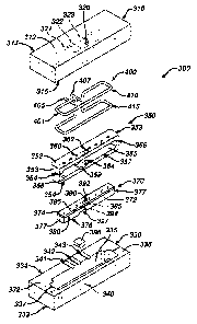
Referring now to FIGS. 4 and 5 an inductively coupled heating fixture
300 useful in the process of the present invention is illustrated. Heating
fixture 300 is seen to have top insulator member 310 and bottom insulator
member 330. Insulator members 310 and 330 are seen to have inner cavities
315 and 335 respectively. Insulator member 310 is seen to have die passage
opening 320 extending through top 312; opening 320 is in communication
with cavity 315. The semi-circular grooves 321, 322 and 323 are seen to
CA 02689113 2009-11-30
WO 2008/151109
PCT/US2008/065488
extend from the rear side 314 to the interior cavity 315. Similarly, bottom
insulator 330 is seen to have die passage opening 340 extending through
bottom 333; opening 340 is in communication with interior cavity 335. The
semi-circular grooves 341, 342 and 343 are seen to extend from the rear side
334 to the interior cavity 335. When assembled, the grooves 321, 322, and
323 align with grooves 341, 342 and 343 to form passages 301 and 302 for the
RF source and passage 303 for the shielding gas. The bottom insulator
member 330 is also seen to have top surface 332 and steps 337 adjoining
lower slot surface 338. The insulator block member 350 is seen to have top
352 and cavity 355 extending therein with lateral opening 357. A plurality of
gas ports 360 extend from the top 352 into and in communication with cavity
355. A die passage 362 extends from the top 352 into cavity 355. Similarly, a
die passage 364 extends from the bottom 354 into cavity 355. The opposed
needle slots 366 are seen to be contained in opposing ends 353 of member
350. Also contained in member 350 is a keyway slot 359 extending from the
bottom interior wall 358 of cavity 355. The metal heater element 370 is seen
to be contained with the cavity 355 of insulator block member 350. The
heater element 370 is seen to have slot 380 extending into the front side 372
of
heater element 370. Slot 380 extends into opposed ends 377 of heater element
370. Extending through the heater element 370 is the die passage 390 having
top passage 392 and bottom passage 394. Die passage 390 is seen to intersect
slot 380. A plurality of gas flow passages 395 are seen to extend down from
the top 374 of heater element 370 into slot 380. The keyway slot 397 is seen
to be contained in the bottom 376 of heater element 370 to receive the key
member 398. The RF induction source 400 is seen to be a tubular conductive
member 401 having an inlet 405 and an outlet 407. The member 401 is bent
to have an upper section 410 and a bottom section 415 such that the metal
heater element 370 and the insulator block member 350 are contained between
the two sections when the heating fixture 300 is assembled.
A side view of the heating fixture 300 is seen in FIG. 5. In order to
assemble the fixture 300, the metal heater element 370 is place within cavity
16
CA 02689113 2009-11-30
WO 2008/151109
PCT/US2008/065488
355 of insulator block 350 such that the slot 380 is facing outward. The key
member 398 is then inserted into the keyway slot 397 and the keyway slot 359
locking heater element 370 into cavity 355. Next, the insulator block 350
containing keyed-in heater element 370 is place between the upper section 410
and the bottom section 415 of RF induction source 400. Then this sub
assembly is placed into the cavity 335 of bottom member 330. The assembly
of the fixture 300 is completed by mounting top insulating member 310 to
bottom member 330, such that the upper section 410 of member 410 and the
upper section of insulating block 350 are contained within the cavity 315. As
seen in FIG. 5, the assembled fixture 300 is seen to have slot 305 resulting
from steps 337 and lower terraced surface 338. Slot 305 is in communication
with slots 366 of insulator block 350 and slot 380 of heater element 370. The
fixture 300 is mounted to a conventional die press. In operation, the RF
induction source 400 is connected to an RF generator. The RF magnetic field
generated by the induction source 400 couples with the heating element 370
invoking an internal RF current that in turn resistively heats the element
370.
Needle blanks are fed through the slots 305, 366, and 380 in the fixture 300
in
an indexed manner. While in the slot 380 contained in heater element 370,
surgical needle blanks are heated by convection and radiation to the desired
temperature prior to moving to a die striking location within the intersection
385 of slot 380 and die passage 390 between the die passages 392 and 394 and
maintained at that temperature while at the die striking location. When
indexed to the intersection 385, upper and lower dies 540 and 542 strike the
needle blanks 610 to produce the desired needle body shape, needle point
shape or suture receiving channel. During the processing, a shielding gas is
optionally connected to the gas port 303 in the insulating blocks 310 and 330.
Referring now to FIGS. 6-9, a needle processing machine 500 is seen.
The machine 500 is seen to have frame 510. Mounted to the frame 510 are the
die press apparatus 520 and the feeder rail 550. Slidably mounted to feeder
rail 550 is the indexing needle blank fixture 570. A plurality of needle
blanks
600 is mounted to a carrier strip 610. Carrier strip 610 is mounted to the
17
CA 02689113 2009-11-30
WO 2008/151109
PCT/US2008/065488
fixture 570 such that the needle blanks are facing toward the die press
apparatus 520. Mounted to the frame 530 of the die press apparatus 520 is the
heating fixture 300. Also mounted to the frame 530 are the upper die 540 and
the lower die 542. In operation, refractory metal alloy needle blanks 600 are
pre-mounted to a carrier strip 610. The strip 610 containing the needle blanks
600 is mounted to the fixture 570. The optional shielding gas is connected to
gas port opening 303 in the fixture 300 such that the shielding gas is flowing
through ports 362 and 395 in the insulator block 350 and heater element 370
and exiting through slot 380 in heater element 370, slots 366 in insulating
block 350, and slot 305 between insulating members 310 and 330. The RF
generator connected to the RF induction source 400 is energized, causing RF
source 400 to emit RF radiation which inductively heats up heater element
370. The fixture 570 is then moved by a conventional index controller and
mechanism such that needles blanks 600 are moved through the slots 302, 366
and 380 and to a die striking position 385 in slot 380. The residence time in
the slot 380 of the heater element is sufficient to effectively heat each
needle
blank 600 to a temperature above the ductile to brittle transition temperature
but below the re-crystallization temperature prior to and during the die
forming operation. The upper and lower dies 340 and 342 are then moved
through the die passages and sufficient force is exerted upon the needle blank
by the dies to effectively form the needle blank into the desired
configuration.
The index process continues until all of the needle blanks 600 on the carrier
strip 610 have been formed. The optional shielding gases useful with the
machine 500 and fixture 300 include: argon, hydrogen, helium, neon, carbon
dioxide, CO/CO2 mixtures, combinations of the aforementioned and the like.
The RF generator coupled to the RF source 400 will be a conventional
generator producing a sufficiently effective frequency, e.g., in the range of
about 1 kilohertz to 10 Megahertz and having a sufficiently effective power
output, e.g., about 1 to 100 kilowatts. The choice of a suitable generator,
frequency range and power output will depend upon various factors including
the size of the RF source, the size and shape and material of construction of
the heating element, and the residence time in the slot of the heating
element,I
18
CA 02689113 2009-11-30
WO 2008/151109
PCT/US2008/065488
.e., the indexing speed. The heater block may be made of conventional metals
and metal alloys such as nickel-based, molybdenum-based, or tungsten-based
alloys. The insulating members and insulator block may be made from
conventional insulating materials such as ceramic fiber insulation.
As an additional benefit associated with the novel thermal forming
methods of the present invention, alloys that may exhibit high DBTT can be
formed into suture needles. For example, in the W-Re alloy system, alloys
with high rhenium concentrations tend to have lower DBTT than alloys with
low rhenium concentration. However, from a commercial perspective,
rhenium has a high raw material cost and can be an exceedingly expensive
component of the alloy. If the thermal forming methods of the present
invention are used, low rhenium concentrations may be used in lieu of high
rhenium concentrations to realize a substantial cost savings. An additional
benefit is that the market price for the finished suture needle may in theory
be
reduced, as raw material costs no longer need to be passed on to the customer,
and use of the tungsten alloys as suture needle materials may be expanded to a
greater number of needle designs.
Furthermore, greater tolerances for impurities in the alloy (that have
the effect of elevating the DBTT) may be permissible if the thermal forming
methods of the present invention are used. Yet another associated benefit is
that supplier availability may broaden, thereby possibly resulting in
decreased
material cost.
Still yet an additional benefit of use of the novel methods of the
present is seen when a needle blank is curved to form a curved or arcuate
suture needle with the shape or configuration of, for example, a, 3/8, or
circle.
During the conventional needle curving process performed at room
temperature, residual stresses are typically imparted to the needle body that
detrimentally impact the yield bend moment of the needle. It is believed that
heat treatment after the curving operation eliminates some or all of such
19
CA 02689113 2009-11-30
WO 2008/151109
PCT/US2008/065488
residual stresses and substantially enhances the yielding bend moment of the
needle. Thermal forming operations to curve the suture needle at elevated
temperatures (e.g. in excess of 900 C) may result in a similar improvement in
yield bend moment.
Heat treating methods for the coloration of refractory alloy suture
needles via the formation of a thin native surface oxide may be applied in
conjunction with the in situ thermal forming methods of the present invention.
Refractory alloy suture needles may thus be colored during needle
manufacturing operations, thus eliminating the need for a subsequent thermal
coloring step. Where coloration is a desired outcome, the use of a
conventional shielding gas should be avoided, or used in combination with a
conventional oxidizing gas However, if coloration is not desired, a shielding
gas may be used.
The following examples are illustrative of the principles and practice
of the present invention, although not limited thereto.
EXAMPLE 1
Needle blanks comprised of a tungsten-26% rhenium alloy with a
nominal starting wire diameter of .203 mm were pressed between two
opposing carbide dies to produce parallel opposed body flats. The tungsten-
26% rhenium material from which the needle blank was made was acquired
from Toshiba Corporation (Yokohama, Japan) and exhibited a breaking
strength of 3450 MPa in wire form. A conventional pneumatic uniaxial press
was used for the experiments with flat carbide dies. The length of the needle
blank, over which body flats were formed, was at least 1 cm. In one set of
experiments the needle blanks were pressed to various thicknesses at room
temperature and visually examined for cracks at 30x magnification with a
stereoscope. It was found that cracks could be formed longitudinally along the
length of the wire when the body flat was coined to a thickness equal to or
less
CA 02689113 2009-11-30
WO 2008/151109
PCT/US2008/065488
than ¨ .175 mm. In a parallel set of experiments, the W-26% Re needle blanks
were resistively heated immediately prior to and during the pressing operation
using the experimental configuration similar to that depicted in FIG. 1. A
conventional AC variac was used to sufficiently deliver and adjust the current
through the needle blank. In this way the needle could be effectively heated
to
above 1000 C as evidenced by the yellow to white glow that was produced.
The entire heating and pressing operation took ¨ 1.5 seconds. Visual
examination at 30x magnification was used to detect cracks. It was found that
needles that were heated to above ¨ 1000 C (yellow to white glow discharge)
could be produced with body flats of 0.15 mm or less without any visually
detectable cracks.
EXAMPLE 2
In order to assess the ductility of the suture needles of Example 1, a
reshape test was performed wherein each needle was held near its proximal
end with suitable, conventional needle holders and bent back and forth through
180 degrees multiple times until fracture of the needle occurred. Each bend
though 90 degrees from the initial shape of the needle was given a 1/2 count.
The total number of counts is a measure of ductility with the higher numbers
indicating greater ductility. Most suture needles are required by their
manufacturers to exhibit a reshape value of at least 1Ø The W-26% Re suture
needles made in Example 1 above exhibited reshape values in excess of 4.0
thereby meeting and exceeding the standard requirement.
The novel methods of the present invention for thermoforming surgical
needles have numerous advantages and benefits. These advantages and
benefits include: production of refractory alloy suture needles with flattened
or I-beam body sections, coined needle points, and suture receiving channels
without cracking or splitting the needle blank and without compromising
ductility and toughness of the suture needle, improved resistance to bending,
stiffness, and strength via thermal curving of the suture needle, coloration
of
21
CA 02689113 2015-05-19
the needle surface via native surface oxide formation in situ during thermal
forming negating the need for subsequent coloration processes, and selection
of lower cost refractory alloys with high DBTT.
Although this invention has been shown and described with respect to
detailed embodiments thereof, it will be understood by those skilled in the
art
that various changes in form and detail thereof may be made.
22