Note: Descriptions are shown in the official language in which they were submitted.
CA 02689401 2009-11-27
WO 2008/157110 PCT/US2008/066300
-1-
CUTTING ELEMENTS FOR CASING COMPONENT DRILL OUT AND
SUBTERRANEAN DRILLING, EARTH BORING DRAG BITS AND TOOLS
INCLUDING SAME AND METHODS OF USE
PRIORITY CLAIM
This application claims the benefit of the filing date of United States Patent
Application Serial Number 11/764,008, filed June 15, 2007, pending.
TECHNICAL FIELD
Embodiments of the present invention relate generally to drilling a
subterranean
bore hole and, more specifically, to drill bits and tools for drilling
subterranean formations
and having a capability for drilling out structures and materials which may be
located at,
or proximate to, the end of a casing or liner string, such as a casing bit or
shoe, cementing
equipment components and cement as well as drilling through the side wall of
the casing
or liner string and surrounding cement.
BACKGROUND
Drilling wells for oil and gas production conventionally employs
longitudinally
extending sections, or so-called "strings," of drill pipe to which, at one
end, is secured a
drill bit of a larger diameter. After a selected portion of the bore hole has
been drilled, a
string of tubular members of lesser diameter than the bore hole, known as
casing, is placed
in the bore hole. Subsequently, the annulus between the wall of the bore hole
and the
outside of the casing is filled with cement. Therefore, drilling and casing
according to the
conventional process typically requires sequentially drilling the bore hole
using drill string
with a drill bit attached thereto, removing the drill string and drill bit
from the bore hole,
and disposing and cementing a casing into the bore hole. Further, often after
a section of
the bore hole is lined with casing and cemented, additional drilling beyond
the end of the
casing or through a sidewall of the casing may be desired. In some instances,
a string of
smaller tubular members, known as a liner string, is run and cemented within
previously
run casing. As used herein, the term "casing" includes tubular members in the
form of
liners.
Because sequential drilling and running a casing or liner string may be time
consuming and costly, some approaches have been developed to increase
efficiency,
CA 02689401 2009-11-27
WO 2008/157110 PCT/US2008/066300
-2-
including reamer shoes and drilling with casing. Reamer shoes employ cutting
elements
on the leading end that can drill through modest obstructions and
irregularities within a
bore hole that has been previously drilled. Reamer shoes also include an inner
section
manufactured from a material which is drillable by drill bits. Accordingly,
when
cemented into place, reamer shoes usually pose no difficulty to a subsequent
drill bit to
drill through. For instance, U.S. Patent No. 6,062,326 to Strong et al.
discloses a casing
shoe or reamer shoe in which the central portion thereof may be configured to
be drilled
through. However, the use of reamer shoes requires the retrieval of the drill
bit and drill
string used to drill the bore hole before the casing with the reamer shoe is
run into the bore
hole.
Drilling with casing employs a drill bit, termed a "casing bit," attached to
the end
of the casing string. The casing bit functions not only to drill the earth
formation, but also
to guide the casing into the bore hole. The casing is, thus, run into the bore
hole as it is
formed by the casing bit, eliminating the necessity of retrieving a drill
string and casing bit
after reaching a target depth where cementing is desired. However, in many
instances
further drilling laterally from the casing or beyond the end of the casing may
be desired,
requiring drilling through the casing side wall or through or around the
casing bit.
Drilling through casing or casing-associated components (casing shoe, casing
bit,
casing wall, cementing equipment and cement, etc.) may result in damage to the
drill bit
or tool run into the casing string. Casing as well as casing-associated
components often
employ iron-based materials in the form of iron-based alloys. Diamond,
including
specifically polycrystalline diamond compacts, or "PDCs" employed as cutting
elements
in conventional fixed cutter bits, or "drag" bits, is reactive with iron at
high temperatures
such as are generated at the cutting edges of such cutting elements during a
drilling
operation. Therefore, using a conventional drag bit or tool using solely PDC
cutting
elements to drill through casing or casing-associated components may severely
deteriorate
the diamond cutting table of the PDC cutting elements, to the extent they are
not suitable
for further drilling through subterranean formations. This is especially true
in high
strength alloy steel or "duplex" alloy steel casings. The drag bit or tool
must then be
retrieved and replaced before drilling resumes.
Special tools known as mills or milling tools have historically been employed
in
order to drill through casing side wall. Unfortunately, most of these tools
are unable to
penetrate both the casing sidewall and adjacent subterranean formation
effectively to any
CA 02689401 2009-11-27
WO 2008/157110 PCT/US2008/066300
-3-
substantial distance. Therefore, the mill must conventionally be retrieved
from the hole
and replaced with a drill bit after drilling through the casing side wall is
completed. Such
a procedure somewhat compromises any time and expense saved by drilling with
casing.
Several devices have been developed for avoiding damage to the milling tool or
the need
to retrieve tool used to drill through the casing before drilling any
substantial distance into
the surrounding formation.
One approach for drilling through casing and casing-associated components
includes employing a drill bit or tool having a face on which two different
types of cutting
elements are disposed. The first type of cutting elements comprise a
superabrasive
material such as polycrystalline diamond and the second type of cutting
elements
comprise an abrasive material such as tungsten carbide. The second type of
cutting
elements exhibit a relatively greater exposure than the first type of cutting
elements, so as
to engage the interior of the casing or casing-associated components, after
which the
second type of cutting elements quickly wear away upon engagement with the
subterranean formation. Such an approach is disclosed in U.S. Patent
Publications
2007/0079995 and 2006/0070771, each of which is assigned to the assignee of
the present
invention.
One drawback associated with providing two sets of cutting elements on a drill
bit
or tool is an inability to provide an optimum cutting element layout for
drilling the
formation after penetration of casing or casing components and surrounding
cement. This
issue manifests itself not only in problems with attaining an optimum cutting
action, but
also in problems, due to the presence of the required two sets of cutting
elements, with
implementing a bit hydraulics scheme effective to clear formation cuttings
using drilling
fluid when any substantial rate of penetration (ROP) is sought.
To enable effective drilling of casing and casing-associated components
manufactured from robust, relatively inexpensive and drillable iron-based
material such
as, for example, high strength alloy steels which are generally non-drillable
by diamond
cutting elements as well as enhanced subsequent drilling effectiveness through
the
surrounding formation, it would be desirable to have a drag bit or tool
offering the
capability of drilling through such casing or casing-associated components,
while at the
same time offering the subterranean drilling capabilities of a conventional
drag bit or tool
employing superabrasive cutting elements.
CA 02689401 2009-11-27
WO 2008/157110 PCT/US2008/066300
-4-
DISCLOSURE OF INVENTION
Embodiments of the present invention comprise a diamond table having at least
a
portion of an exterior surface thereof coated with another superabrasive
material which is
non-reactive with iron-based materials.
Embodiments of the present invention comprise an apparatus for drilling
through
casing or casing-associated components using cutting elements comprising a
superabrasive material for contacting the casing or casing-associated
components which is
non-reactive with iron-based materials and which may be worn away after
penetration of
the casing or casing-associated component to expose a superabrasive material
in the form
of a diamond table for drilling through an adjacent subterranean formation
using the
exposed diamond of the cutting element.
A method of drilling a bore hole is also provided. The method includes bore
hole
contacting and cutting through at least one casing element and into an
adjacent
subterranean formation using an apparatus bearing cutting elements which
comprise a
superabrasive material which is non-reactive with iron-based materials
covering at least a
portion of an exposed surface of a diamond table using substantially only the
non-reactive
superabrasive material of the cutting elements, wearing away the non-reactive
superabrasive material to expose at least a portion of the diamond tables of
the cutting
elements and drilling a bore hole into the adjacent subterranean formation
with the
apparatus, using the exposed at least a portion of the diamond tables of the
cutting
elements.
BRIEF DESCRIPTION OF DRAWINGS
FIG. 1 illustrates a drill bit in the form of a fixed cutter or so-called
"drag" bit,
according to one example of the present invention.
FIGS. 2A-2E illustrate perspective views along with an associated cross-
section
view of cutting elements of suitable configurations according to different
exemplary
implementations of the present invention.
FIG. 3 is a drill bit or casing bit according to one embodiment of the present
invention drilling through a casing component at the end of a previously
positioned and
cemented casing string.
CA 02689401 2009-11-27
WO 2008/157110 PCT/US2008/066300
-5-
FIG. 4 illustrates a drill bit or casing bit according to one embodiment of
the
present invention drilling through the side wall of a previously positioned
and cemented
casing string.
FIG. 5 is a flow diagram illustrating a method of drilling a bore hole after a
casing
string has been positioned and cemented into place.
MODE(S) FOR CARRYING OUT THE INVENTION
In the following detailed description of the invention, numerous specific
details are
set forth in order to provide a thorough understanding of the invention.
However, one of
ordinary skill in the art would recognize that the invention may be practiced
without these
specific details. In other instances, well known methods, procedures, and/or
components
have not been described in detail so as not to unnecessarily obscure aspects
of the
invention.
In the following description, certain terminology is used to describe certain
features of one or more embodiments of the invention. For instance, the term
"casing-
associated components" means and includes drill shoes, drill bits, casing
wall, cementing
equipment and/or cement associated with a casing or liner string. "Iron-based
material"
means and includes materials, such as steel alloys, including without
limitation high
chrome duplex steel alloys, having a sufficient proportion of iron therein so
as to be
reactive with diamond at temperatures commonly generated during machining
processes.
Depending on whether the diamond is in the form of PDC or natural diamonds,
and
further depending on the presence and make-up of a catalyst material with PDC,
the
carbon may begin to react with the iron-based material at around 750 C.
One embodiment of the present invention provides a drag bit or tool for
drilling
through casing or casing-associated components comprising an iron-based
material as
well as further drilling through subterranean formations. Further embodiments
of the
present invention comprise cutting elements suitable for use with a drill bit
or tool which
are capable of drilling through both casing and casing-associated components
comprising
an iron-based material and, subsequently, through an adjacent subterranean
formation, and
methods of drilling.
FIG. 1 illustrates a drill bit in the fonn of a fixed cutter or so-called
"drag" bit,
according to one embodiment of the present invention. Drill bit 100 includes a
body 102
having a face 104 and generally radially extending blades 106, forming fluid
courses 108
CA 02689401 2009-11-27
WO 2008/157110 PCT/US2008/066300
-6-
therebetween extending to junk slots 110 between circumferentially adjacent
blades 106.
Bit body 102 may comprise a tungsten carbide matrix or a steel body, both as
well known
in the art.
Blades 106 may include a gage region 112 which is configured to define the
outermost radius of the drill bit 100 and, thus, the radius of the wall
surface of a bore hole
drilled thereby. Gage regions 112 comprise longitudinally upward (as the drill
bit 100 is
oriented during use) extensions of blades 106 and may have wear-resistant
inserts or
coatings, such as cutting elements, or hardfacing material, on radially outer
surfaces
thereof as known in the art to inhibit excessive wear thereto.
Drill bit 100 may also be provided with pockets 114 in blades 106 which may be
configured to receive cutting elements 116. Cutting elements 116 may be
affixed upon
the blades 106 of drill bit 100 by way of brazing, welding, or as otherwise
known in the
art. Cutting elements 116 are configured to be capable of cutting through
subterranean
formations after cutting through the material of casing or casing-associated
components.
Cutting elements 116 may, therefore, comprise a diamond table portion suitable
for
drilling through subterranean features at least partially covered with another
superabrasive
material which is non-reactive with iron and suitable for drilling through
casing or casing-
associated components. As used herein, the term "diamond table" is non-
limiting of the
physical configuration of the diamond portion of the cutting element, and
encompasses
both single crystal diamond, diamond-to-diamond bonded aggregates of diamond
grit and
structures of a hard material, for example, a carbide, impregnated with
natural diamond or
synthetic diamond grit, or a combination thereof. Such structures are
exemplified by so-
called "impregnated segments" used on drag bits for extremely hard formation
drilling.
Further, the term "diamond table" means a structure of sufficient strength and
impact
resistance to be suitable for cutting subterranean (rock) formations.
The diamond table portion of cutting elements 116 may comprise a
polycrystalline
diamond compact (PDC) which may be characterized as a mutually bonded mass of
diamond particles or "grit," exhibiting diamond-to-diamond bonds. PDCs are
formed
from a volume of diamond particles subjected, in the presence of a catalyst,
to ultra-high
pressure, ultra-high temperature (HPHT) conditions, as is well known to those
of ordinary
skill in the art. It is also contemplated that the diamond table portion may
comprise a
thermally stable polycrystalline product (TSP) which may be characterized as a
PDC from
which the catalyst has been substantially removed, a single crystal nature
diamond, or a
CA 02689401 2009-11-27
WO 2008/157110 PCT/US2008/066300
-7-
diamond grit-impregnated segment, as known in the art and as may be selected
in
consideration of the subterranean formation or formations to be drilled. Such
a diamond
table portion in the fonn of a PDC is conventionally disc-shaped and may be
formed on
and bonded to a supporting substrate of, for example, cemented tungsten
carbide, as is
well known in the art. If another type of diamond table is employed of the
type described
above, the diamond table may be directly furnaced into a matrix-type bit body,
or brazed
to such a body or to a steel-body bit. At least a portion of a diamond table
comprising a
TSP or a natural diamond may be treated to facilitate metallurgical bonding
thereof to a
matrix-type bit body, again as is well known in the art. Specifically, such a
diamond table
material may be coated with a single layer or multiple layers of a refractory
material, as
known in the art and disclosed in United States Patents 4,943,488 and
5,049,164.
The superabrasive material which is non-reactive with iron-based materials
may,
in some embodiments, comprise a cubic boron nitride (CBN) film disposed on or
over at
least a portion of an exterior surface of the diamond table. However, the non-
reactive
superabrasive portion may comprise another superabrasive material that is not
attacked by
iron. By way of example, cubic zirconia (Zr02) or synthetic moissanite (a
crystallized
silicon carbide) may be employed. The CBN film may be formed on and bonded to
the
diamond table by any suitable technique known in the art. For example, as
disclosed in
U.S. Patent No. 5,597,625 to Ong et al., a CBN film may be deposited on
diamond using
chemical vapor deposition (CVD) techniques.
In other embodiments, the superabrasive which is non-reactive with iron-based
materials may comprise a discrete mass formed on a diamond table, or bonded
thereto.
For example, CBN grit may be disposed adjacent to a diamond table and formed
into a
CBN mass bonded to the diamond table under HPHT conditions using techniques
disclosed in United States Patents 3,743,489 and 4,374,651 As another
approach, a CBN
preform may be metallurgically bonded to a diamond table using techniques
disclosed in
previously referenced United States Patents 4,943,488 and 5,049,164.
FIGS. 2A-2E illustrate perspective views and associated cross-section views of
cutting elements 200 of various configurations according to different
embodiments of the
present invention. For the sake of clarity, like numerals have been used to
identify like
features in FIGS. 2A-2E. An embodiment of a cutting element 200 of the
invention is
illustrated in FIG. 2A. A substrate 202 may be provided, comprising cemented
tungsten
carbide or any material commonly known in the art. A diamond table portion 204
may be
CA 02689401 2009-11-27
WO 2008/157110 PCT/US2008/066300
-8-
disposed on the substrate 202 and bonded thereto. Diamond table portion 204
may
comprise, for example, a PDC table configured conventionally as a disc as
known to those
of ordinary skill in the art. A superabrasive material comprising portion 206
which is non-
reactive with iron-based materials (also termed a "non-reactive
superabrasive") may be
disposed over the diamond table portion 204 such that the diamond table
portion 204 is
sandwiched between the substrate 202 and the non-reactive superabrasive
portion 206.
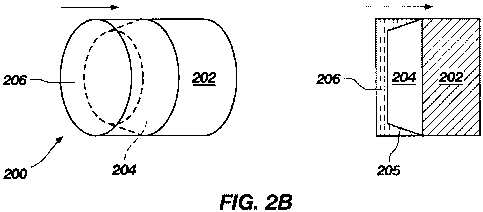
In another embodiment of the present invention depicted in FIG. 2B, a
substrate 202 may be provided with diamond table portion 204 disposed thereon
and
bonded thereto. Diamond table portion 204 may be configured in a frustoconical
shape to
extend away from substrate 202 with a tapered side wall 205 such that the
diameter of
diamond table portion 204 decreases as the distance from substrate 202
increases. The
diameter of diamond table portion 204 at the surface which is bonded to
substrate 202
may be substantially the same as the diameter of substrate 202. The sidewall
of diamond
table portion 204 may taper linearly inwardly as shown, it may taper arcuately
with a
radius that is concave or convex, it may taper inwardly with side wall
geometries such as
waves, steps, scallops and/or teeth, or may exhibit any other geometry known,
for
example, as described in the aforementioned U.S. Patent Application
2007/0079995.
Non-reactive superabrasive portion 206 may be disposed over diamond table
portion 204
and configured to encapsulate diamond table portion 204 on all sides except
the side
which is bonded to substrate 202. Non-reactive superabrasive portion 206 may
have
substantially the same outer cylindrical shape as substrate 202 or (not shown)
may evenly
coat the exterior surfaces of diamond table portion 204 and, so exhibit a
frustoconical
outer surface.
In another embodiment of the present invention, as depicted in FIG. 2C,
diamond
table portion 204 may be disposed on and bonded to substrate 202. Diamond
table
portion 204 may be configured cylindrically with a diameter smaller than the
diameter of
substrate 202, and be concentric therewith so as to expose an annular shoulder
208 on the
end of substrate 202 abutting diamond table portion 204. Non-reactive
superabrasive
portion 206 may be disposed over diamond table portion 204 so as to
encapsulate
diamond table portion 204 on all exposed sides. Non-reactive superabrasive
portion 206
may have substantially the same outer diameter as substrate 202.
FIG. 2D illustrates another embodiment of the present invention including a
substrate 202. Substrate 202 may have diamond table portion 204 disposed
thereon and
CA 02689401 2009-11-27
WO 2008/157110 PCT/US2008/066300
-9-
bonded thereto. In this embodiment, the end of the diamond table portion 204
abutting
substrate 202 may be configured to be of the same shape and size as substrate
202 such
that the outer side wall of diamond table portion 204 and that of substrate
202 may be
substantially coextensive. A shelf or shoulder 210 may be formed on a portion
of the end
of diamond table portion 204 facing away from substrate 202, wherein non-
reactive
superabrasive portion 206 may be disposed. As noted above, the non-reactive
superabrasive portion may comprise a preformed CBN mass bonded to diamond
table
portion 204, or a CBN mass formed on diamond table portion 204 under HPHT
conditions. As shown, non-reactive superabrasive portion 206 may have a front,
or
cutting face portion 212 coextensive with cutting face 214 of diamond table
portion 204,
and a side wall coextensive with the side wall 205 of diamond table portion
204.
Another configuration for an embodiment of a cutting element 200 is
illustrated in
FIG. 2E. Substrate 202 may have diamond table portion 204 disposed thereon and
bonded
thereto. Diamond table portion 204 may be of cylindrical configuration with an
outer
diameter smaller than, and concentric with, the outer diameter of substrate
202. Non-
reactive superabrasive portion 206 may be disposed around the side wall 205 of
diamond
table portion 204 in a manner similar to the structure of FIG. 2C, except non-
reactive
superabrasive portion 206 does not extend over cutting face 214 of diamond
table
portion 204.
Each of the preceding embodiments illustrated in FIGS. 2A-2E positions
non-reactive superabrasive portion 206 to contact and cut casing or any casing-
associated
component comprising an iron-based material to drill therethrough, while
preventing
damage to diamond table portion 204 which may result from contacting iron-
based
material the casing or casing-associated components under high temperatures
generated
during drilling. Casing, casing-associated component, and/or subterranean
features move
across the cutting elements 200 in the direction of the arrows. After drilling
through the
casing or one or more casing-associated components and through cement which
conventionally surrounds casing and is disposed at the end thereof adjacent
the bottom of
a bore hole, non-reactive superabrasive portion 204 may wear away upon
encountering the
adjacent subterranean formation, exposing diamond table portion 204 for
further drilling.
The appropriate thickness of non-reactive superabrasive portion 206, including
a
safety margin, may be calculated by determining or predicting the volume, in
terms of
thickness, of the non-reactive superabrasive portion 206 which may be worn
away when
CA 02689401 2009-11-27
WO 2008/157110 PCT/US2008/066300
-10-
drilling through the iron-based material of casing or casing-associated
components. The
thickness of non-reactive superabrasive portion 206 may be such that the
thickness of the
non-reactive superabrasive portion 206 is substantially but not completely
worn away by
the time the drill bit or milling tool has drilled or milled, respectively,
through any casing
or casing-associated components. In this manner, the drill bit may be used to
drill or mill
through iron-based materials using the non-reactive superabrasive portion
before there is a
risk of exposure of the diamond table portion 204. At any time after the iron-
based
material has been completely penetrated, the non-reactive portion may be
quickly worn
away and the diamond table 204 exposed to drill a bore hole into the
subterranean
formation.
Although the examples in FIGS. 2A-2E show each cutting element in a circular
configuration, it will be apparent to one of ordinary skill in the art that
the cutting elements
may be configured in a variety of suitable geometric shapes including, but not
limited to,
ovoid, rectangular, tombstone, etc. The basic principles described above as
they relate to
the illustrated circular configurations also apply to any variation of
geometric
configurations. For example, the configuration illustrated in FIG. 2B may
apply as well to
an ovoid shape, in which diamond table portion 204 may have a base that is
bonded to the
substrate 202 and which is configured to be the same shape as substrate 202
and which
extends away from substrate 202 with sloping side walls such that the forward
surface has
a similar shape but smaller dimensions than the base. Furthermore, the cutting
elements 200 may be configured with non-planar (for example, dome-shaped)
cutting
faces, and to include chamfered or radiused cutting edges at the cutting face
periphery, as
known in the art. In the case of TSP, natural diamond or impregnated segment-
type
diamond tables, the cutting element geometry may be of any suitable
conventional
configuration as known in the art.
FIG. 3 schematically illustrates a drill bit according to one embodiment of
the
present invention drilling through the end of a previously positioned and
cemented casing
and bit. The drill bit 312 may comprise, for example, drill bit 100 as
depicted in FIG. 1.
Casing 302 including a casing-associated component 304, which may for example
and
without limitation comprise a casing bit or a float shoe at the distal end
thereof is
positioned in bore hole 306 and cemented therein with cement sheath 308.
Subsequently,
drill string 310 and drill bit 312 disposed within casing 302 may be used to
engage the
casing-associated component 304 of first casing 302 near the bottom of bore
hole 306.
CA 02689401 2009-11-27
WO 2008/157110 PCT/US2008/066300
-11-
The cutting elements (not shown) of second drill bit 312 may include a diamond
table
portion and a non-reactive superabrasive portion, as described above with
respect to
FIGS. 2A-2E. The non-reactive superabrasive portion may mill through the
casing-
associated components of the first casing 302 and wear down during the milling
process
such that when second drill bit 312 engages subterranean features 314, the
diamond table
portion is exposed.
FIG. 4 illustrates a tool according to one embodiment of the present invention
drilling through the side wall of a previously positioned and cemented casing
402 and bit.
Casing 402 including, for example, casing bit 404 at the distal end thereof is
positioned in
bore hole 406 and cemented in the bore hole with cement sheath 408.
Subsequently, drill
string 410 and tool 412, which may be configured as a milling tool or as a
drill bit, may
engage the side wall of first casing 402 under the guidance of a whipstock
(not shown), as
is well known in the art. At least some of the cutting elements (not shown) of
tool 412,
particularly those at a periphery of tool 412, may include a diamond table
portion and a
non-reactive superabrasive portion disposed over at least a portion of the
diamond table,
as described above with respect to FIGS. 2A-2E. The non-reactive superabrasive
portion
may be used to mill through the casing side wall of casing 402 and cement
sheath 408 and
wear down thereafter upon encountering subterranean formation 414.
FIG. 5 is a flow diagram schematically illustrating a method of drilling a
bore hole
after a previous casing has been positioned and cemented into place. A first
bore hole
may be drilled to a desired depth 502 and a casing may be positioned and
affixed
therein 504. The casing may be positioned during drilling by using a drilling
with casing
method and the casing may be affixed with cement. However, it will be apparent
to those
of skill in the art that any method known in the art may be used for forming
the first bore
hole and disposing the casing inside the first bore hole.
A window or opening may be drilled or milled through a side wall portion of
the
casing or through a casing-associated component at the distal end thereof
using,
respectively a milling tool or a drill bit 506. The drill bit or milling tool
may include a
plurality of cutting elements as previously described herein, which may be
configured to
employ a non-reactive superabrasive material to initially contact any casing-
associated
components to be milled, such material being subsequently worn away and a
diamond
table employed to drill an adjacent subterranean formation.
CA 02689401 2009-11-27
WO 2008/157110 PCT/US2008/066300
-12-
The non-reactive superabrasive material may be worn away to expose the diamond
table 508 during the milling of the window or opening. Once the drill bit is
through the
casing or casing-associated components, the exposed diamond table may be used
to drill
through subsequent subterranean features 510. This process may be repeated
with
subsequent drill strings and/or casing strings until a desired depth/location
is reached.
While certain embodiments have been described and shown in the accompanying
drawings, such embodiments are merely illustrative and not restrictive of the
scope of the
invention, and this invention is not limited to the specific constructions and
arrangements
shown and described, since various other additions and modifications to, and
deletions
from, the described embodiments will be apparent to one of ordinary skill in
the art. Thus,
the scope of the invention is only limited by the literal language, and
equivalents, of the
claims which follow.