Language selection

Search

Patent 2689933 Summary

Third-party information liability

Some of the information on this Web page has been provided by external sources. The Government of Canada is not responsible for the accuracy, reliability or currency of the information supplied by external sources. Users wishing to rely upon this information should consult directly with the source of the information. Content provided by external sources is not subject to official languages, privacy and accessibility requirements.

Claims and Abstract availability

Any discrepancies in the text and image of the Claims and Abstract are due to differing posting times. Text of the Claims and Abstract are posted:

  • At the time the application is open to public inspection;
  • At the time of issue of the patent (grant).
(12) Patent Application: (11) CA 2689933
(54) English Title: SELF-ADHESIVE ANTENNA FOR AN RFID SYSTEM, IN PARTICULAR AN RFID LABEL, AND METHOD FOR THE PRODUCTION THEREOF
(54) French Title: ANTENNE AUTO-COLLANTE POUR SYSTEME RFID, EN PARTICULIER POUR ETIQUETTE RFID, ET SON PROCEDE DE REALISATION
Status: Dead
Bibliographic Data
(51) International Patent Classification (IPC):
  • G06K 19/077 (2006.01)
(72) Inventors :
  • BOHN, MARTIN (Germany)
(73) Owners :
  • BIELOMATIK LEUZE GMBH + CO. KG (Germany)
(71) Applicants :
  • BIELOMATIK LEUZE GMBH + CO. KG (Germany)
(74) Agent: FETHERSTONHAUGH & CO.
(74) Associate agent:
(45) Issued:
(86) PCT Filing Date: 2008-06-04
(87) Open to Public Inspection: 2008-12-11
Examination requested: 2013-03-26
Availability of licence: N/A
(25) Language of filing: English

Patent Cooperation Treaty (PCT): Yes
(86) PCT Filing Number: PCT/EP2008/004432
(87) International Publication Number: WO2008/148527
(85) National Entry: 2009-12-01

(30) Application Priority Data:
Application No. Country/Territory Date
10 2007 026 720.9 Germany 2007-06-06

Abstracts

English Abstract


The invention relates to a self-adhesive antenna for an RFID system, in
particular an
RFID label, wherein, according to the invention, the antenna (1), from a sheet
of
aluminum (7) of a gauge of 1 µm - 20 µm, in particular approximately 10
µm, is glued to
the front of an adhesive material (3) and punched out, wherein an adhesive
layer (4) is
provided on the back side of the adhesive material (3).


French Abstract

La présente invention concerne une antenne auto-collante destinée à un système RFID, en particulier à une étiquette RFID, l'antenne (1) étant selon l'invention réalisée par collage à partir d'un film d'aluminium (7) ayant une épaisseur de 1 µm - 20 µm, en particulier d'environ 10 µm sur le côté avant d'une matière adhésive (3), et matriçage, la matière adhésive (3) présentant sur son côté arrière une couche d'adhésif (4).

Claims

Note: Claims are shown in the official language in which they were submitted.


-7-


Claims


1. A self-adhesive antenna for an RFID system, in particular for
an RFID label, characterized in that the antenna (1) composed
of an aluminum foil (7) having a gauge of 1 µm - 20 µm, in
particular about 10 µm, is glued to the front side of an
adhesive material (3) and punched out, wherein the adhesive
material (3) is provided with an adhesive layer (4) on its
back side.


2. The antenna according to claim 1, characterized in that the
adhesive layer (4) on the back of the adhesive material (3) is
covered by a removable carrier material (5).


3. A method for producing a self-adhesive antenna according to
claim 1 or 2, characterized in that individual antennas (1)
are punched out of an aluminum foil (7) glued to the front
side of a web-like adhesive material (3), wherein the adhesive
material (3) has an adhesive layer (4) on its back side and
that the residual punch grate (15) with the residual aluminum
foil is removed after the punching.


4. The method according to claim 3, comprising the following
steps:

1. A web-like aluminum foil (7) is removed from a roll (6,
21),
2. the aluminum foil (7) is provided with an adhesive layer
(2) on its back side,
3. a web-like adhesive material (3) is glued onto the
adhesive layer (2), said adhesive material having an
adhesive layer (4) on its back side,


-8-

4. individual antennas (1) are then punched out of the
aluminum foil (7), and
5. the residual punch grate (15) of aluminum foil (7) is
removed.


5. The method according to claim 3 or 4, characterized in that an
adhesive material (3) is glued onto the back side of the
aluminum foil (7), which is covered on its averted back side
by a carrier material (5) which is glued on in such a manner
that it can be removed and which is punched out with the
adhesive material (3) when the aluminum foil (7) is punched
and in this way antennas (1) with adhesive material (2)
punched out in the form of antennas remain on the carrier
material (5).


6. The method according to any one of the claims 3 to 5,
characterized in that the adhesive layer (2) is applied to the
back side of the aluminum foil (7) in the form of a transfer
adhesive.


7. The method according to any one of the claims 3 to 6,
characterized in that the adhesive layer (2) is first applied
to a web-like carrier material (18) and then transferred from
it to the back side of the aluminum foil (7).


8. The method according to any one of the claims 3 to 7,
characterized in that a self-adhesive material (12) is applied
to the back side of the aluminum foil prior to the punching,
wherein the adhesive layer (2) is applied to the top layer of
the self-adhesive material (12) serving as adhesive material
(3) prior to joining it with the aluminum foil (7).


9. The method according to any one of the claims 3 to 5,


-9-


characterized in that a composite material comprised of
aluminum foil (7) and a carrier material (20) is used as
starting material which is removably glued to the back side of
the aluminum foil (7), wherein the adhesive layer (2) remains
on the aluminum foil (7) after removal.

Description

Note: Descriptions are shown in the official language in which they were submitted.


CA 02689933 2009-12-01
DESCRIPTION

Self-Adhesive Antenna For An RFID System, In Particular An RFID
Label, And Method For The Production Thereof

The invention relates to a self-adhesive antenna for an RFID
system, in particular for an RFID label, and a method for the
production thereof.

As is generally known, RFID systems comprise a transponder which
consists of an RFID chip and an RFID antenna. RFID labels are, as
is known, produced in such a way that a so-called RFID inlay with
a transponder is arranged between a web-like cover material
provided with an adhesive layer on the underside and a carrier
material which is also web-shaped and can be pulled off from the
adhesive layer. Therefore, the RFID inlay comprises an RFID chip
fastened to a flat antenna and electrically connected with it,
wherein the RFID antenna is arranged on an antenna foil.

Various methods are known for producing RFID antennas. According
to one method, the antenna contour is etched from a foil. This
method is slow, expensive and pollutes the environment.
Alternatively, the antenna contour can be applied directly to a
correspondingly formed web material by metallization. It was also
already proposed to produce the antennas by imprinting with a
conductive paint, for example a silver conductive paint. This
method is also expensive and, insofar as the paints contain heavy
metals, detrimental to the environment. PET is used most often as
web-shaped substrate onto which the flat antennas are applied. It
is not recyclable.


CA 02689933 2009-12-01

- 2 -

Therefore, the object of the invention is to provide an antenna for
an RFID system which can be produced from easy-to-recycle material
at reduced costs.

This object is solved with the features of claim 1. According to
the invention, the antenna is produced from a sheet of aluminum of
a low gauge of between 1 m- 20 m, preferably of about 10 m.
Aluminum foils of this gauge are produced as a mass-produced item,
for example for household foils. Papers, which can also be easily
recycled, are preferably used as carrier materials.

The aluminum foil wound in rolls can be further processed with
rotating tools in a simplified manner in RFID machines for
producing RFID labels. In this way, an electrically optimized UHF
antenna can be produced in a simplified manner. Claim 3 contains
the basic method for producing self-adhesive RFID labels according
to the invention. Claims 4 to 8 claim various advantageous
variations of the production method for various applications.

The drawings serve to describe the invention with reference to a
simplified example of an embodiment.

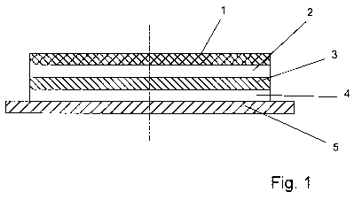
Fig. 1 show the section through a self-adhesive antenna.
Figures
2 to 6 show various methods for producing antennas.

Fig. 7 shows a section of a web-shaped carrier material with a
row of glued-on antennas.

The antennas shown in section in Fig. 1 and in a top view in Fig.
7 are provided for use in an RFID system, in particular for an RFID
label. Generally, self-adhesive RFID labels comprise an RFID inlay


CA 02689933 2009-12-01

- 3 -

in which an RFID chip and an RFID antenna are glued onto a web-like
or curved material. An RFID label of this type and a method for
its production are described e.g. in WO 2005/076206 Al.

The antenna 1, which can be used as a UHF antenna, is punched out
of a thin aluminum foil which has a gauge of 1 m to 20 m, in
particular of about 10 m. The antenna 1 is glued to the front of
a web-shaped or curved adhesive material 3, which is preferably
composed of paper, by means of an adhesive layer 2. The adhesive
material 3 is provided with an adhesive layer 4 on its back side.
The adhesive layer 4 is covered by a web-like or curved carrier
material 5 which is glued on in such a way that it can be removed.
Preferably, siliconized paper is used as carrier material 5. The
adhesive layer 4 adheres more strongly to the adhesive material 3
than to the carrier material 5, so that, after the carrier material
has been removed, an adhesive layer remains on the back side of
the adhesive material 3. By means of this adhesive layer, an
antenna 1 adhering to the adhesive material 3 can be firmly glued
to a material, e.g. to an inlay material.

In Figs. 2 to 4, three manufacturing processes for the self-
adhesive antennas 1 are produced, wherein aluminum foil as antenna
material having a gauge of between 10 m and 20 m, preferably
about 16 m, in web-form is removed from a roll 6. The back side
of the removed aluminum foil 7 is then provided with the adhesive
layer 2. In the method according to Fig. 2, the adhesive layer 2
is applied in the form of a transfer adhesive. In a transfer
adhesive, the adhesive layer is covered on both sides by a covering
material 8 and a carrier material 9. The transfer adhesive is
removed from a roll 10 and placed on the back side of the aluminum
foil 7, whereby the covering material 8 is removed prior to contact
with the aluminum foil 7. When in contact with the aluminum foil
7, the transfer adhesive deposits its adhesive layer 2 to the foil


CA 02689933 2009-12-01

- 4 -

7, then the carrier material 9 of the transfer adhesive is also
removed and wound into a roll 11. There is now an aluminum foil 7
with an adhesive layer 2. A web-like or curved self-adhesive
material 12, which is removed from a roller 13 for this purpose, is
then glued onto the adhesive layer 2. The self-adhesive material
12 consists of the adhesive material 3 as cover layer which is
provided with the adhesive layer 4 on its back side and which is in
turn covered by the carrier material 5.

The composite material composed of carrier material 5, adhesive
material 3 and aluminum foil 1 with adhesive layers 2, 4 arranged
between them is then led through a rotary punching machine 14. The
aluminum foil 7 with the adhesive material 3 is punched out by the
rotary punching machine 14 to form individual antennas 1. The
punching grate 15 consisting of the residual aluminum foil 7 and
the residual adhesive material 3 is then removed and wound to form
a roll 16 as recyclable waste. The antennas 1 with the adhesive
material 3 located below it and also punched out in the form of an
antenna remain on the web-like carrier material 5 and are then
wound with it to form a roll 17. The roll 17 thus comprises the
series of individual antennas 1 shown in Fig. 6 which are glued
together with the adhesive material 3 and glued with it on the
carrier material 5 so as to be removable.

Since the thin aluminum foil 7 with the adhesive material 3 glued
to the back side is reinforced, it is possible to punch out the
individual antenna 1 and to also remove the punching grate 5
without the aluminum foil tearing. Therefore, an extremely thin,
inexpensive aluminum foil can be used as antenna material. At the
same time, it is possible to use the antenna material in roll form
as starting material and to use it on the known machines for
processing web-like material with rotary tools. Aluminum as
antenna material is food and drug tolerant and easily conductive


CA 02689933 2009-12-01
- 5 -

for use as UHF antenna.

The method shown in Fig. 3 corresponds to the method previously
described in Fig. 1 with the exception that the adhesive layer on
the back of the aluminum foil 7 is prepared differently. To this
end, a carrier material composed of silicone paper is removed from
a roll 18 and first provided with the adhesive layer 2 on its top
side by means of a hot-melt applied by a fishtail die 19. The
adhesive layer 2 is then transferred to the back side of the
aluminum foil 7 in the manner described above. The carrier
material 9 is thereby removed again from the aluminum foil 7 and
wound into a roll 11.

In the method according to Fig. 4, the adhesive layer 2 is first
applied to the top side of the top layer of the self-adhesive
material 12 before the latter is joined with the aluminum foil 7.
It is also applied by means of a fishtail die 19 as a hot-melt
application. In this version, the top layer of the self-adhesive
material 12 simultaneously serves as adhesive material layer 3.
An embodiment is shown in Fig. 5 in which a composite material
composed of aluminum foil 7 and a silicone carrier material 20 is
used as starting material, wherein the carrier material 20 is
removably glued to the back side of the aluminum foil 7. When
removing the carrier material 20, the adhesive layer 2 on the back
side of the aluminum foil remains. The composite material 7, 20 is
removed from a roll 21, the carrier material 20 is then removed and
wound up into a roll 22. There is now an aluminum foil 7 with an
adhesive layer 2 on the back side which is first joined with a
self-adhesive material 12 in the manner described for the preceding
embodiments before the antennas 1 are punched out.

In Fig. 6, an embodiment is shown in which a web-like composite


CA 02689933 2009-12-01

- 6 -

material consisting of an aluminum foil 7, an adhesive material 3
and a silicone carrier material 5 is used as starting material.
The aluminum foil is glued to the front side of the adhesive
material 3 and the carrier material 5 is glued to the back side of
the aluminum foil 7 in such a way that it can be removed. When
removing the carrier material 5, the adhesive layer 2 remains on
the back side of the adhesive material 3. The composite material
7, 3, 5 is removed from a roll 23, the antennas 1 are then punched
out. Preferably, they are also punched out through the adhesive
material 3. An antenna structure reinforced with the adhesive
material 3 and a correspondingly reinforced punch grate 15 are
produced in this way. After the punching, the residual punch grate
15 with the residual aluminum foil 7 and, if applicable, with the
residual adhesive material 3 is removed and wound into a roll 16.
The silicone carrier 5 with the antennas 1 glued on and reinforced
by the adhesive material 3 is then wound up into a roll 17.

Representative Drawing
A single figure which represents the drawing illustrating the invention.
Administrative Status

For a clearer understanding of the status of the application/patent presented on this page, the site Disclaimer , as well as the definitions for Patent , Administrative Status , Maintenance Fee  and Payment History  should be consulted.

Administrative Status

Title Date
Forecasted Issue Date Unavailable
(86) PCT Filing Date 2008-06-04
(87) PCT Publication Date 2008-12-11
(85) National Entry 2009-12-01
Examination Requested 2013-03-26
Dead Application 2016-03-02

Abandonment History

Abandonment Date Reason Reinstatement Date
2015-03-02 R30(2) - Failure to Respond
2015-06-04 FAILURE TO PAY APPLICATION MAINTENANCE FEE

Payment History

Fee Type Anniversary Year Due Date Amount Paid Paid Date
Application Fee $400.00 2009-12-01
Maintenance Fee - Application - New Act 2 2010-06-04 $100.00 2010-05-21
Maintenance Fee - Application - New Act 3 2011-06-06 $100.00 2011-05-25
Maintenance Fee - Application - New Act 4 2012-06-04 $100.00 2012-05-24
Request for Examination $800.00 2013-03-26
Maintenance Fee - Application - New Act 5 2013-06-04 $200.00 2013-05-23
Maintenance Fee - Application - New Act 6 2014-06-04 $200.00 2014-05-23
Owners on Record

Note: Records showing the ownership history in alphabetical order.

Current Owners on Record
BIELOMATIK LEUZE GMBH + CO. KG
Past Owners on Record
BOHN, MARTIN
Past Owners that do not appear in the "Owners on Record" listing will appear in other documentation within the application.
Documents

To view selected files, please enter reCAPTCHA code :


To view images, click a link in the Document Description column. To download the documents, select one or more checkboxes in the first column and then click the "Download Selected in PDF format (Zip Archive)" or the "Download Selected as Single PDF" button.

List of published and non-published patent-specific documents on the CPD .

If you have any difficulty accessing content, you can call the Client Service Centre at 1-866-997-1936 or send them an e-mail at CIPO Client Service Centre.


Document
Description 
Date
(yyyy-mm-dd) 
Number of pages   Size of Image (KB) 
Abstract 2009-12-01 1 10
Claims 2009-12-01 3 77
Drawings 2009-12-01 7 58
Description 2009-12-01 6 246
Representative Drawing 2009-12-01 1 7
Cover Page 2010-02-12 1 36
PCT 2009-12-01 4 147
Assignment 2009-12-01 3 81
Prosecution-Amendment 2013-03-26 2 81
Prosecution-Amendment 2014-08-28 2 56
Correspondence 2015-01-15 2 57