Language selection

Search

Patent 2689949 Summary

Third-party information liability

Some of the information on this Web page has been provided by external sources. The Government of Canada is not responsible for the accuracy, reliability or currency of the information supplied by external sources. Users wishing to rely upon this information should consult directly with the source of the information. Content provided by external sources is not subject to official languages, privacy and accessibility requirements.

Claims and Abstract availability

Any discrepancies in the text and image of the Claims and Abstract are due to differing posting times. Text of the Claims and Abstract are posted:

  • At the time the application is open to public inspection;
  • At the time of issue of the patent (grant).
(12) Patent: (11) CA 2689949
(54) English Title: DOWN HOLE APPARATUS FOR GENERATING A PULSING ACTION
(54) French Title: APPAREIL DE FOND CONCU POUR GENERER DES PULSATIONS
Status: Expired and beyond the Period of Reversal
Bibliographic Data
(51) International Patent Classification (IPC):
  • E21B 28/00 (2006.01)
  • E21B 07/24 (2006.01)
(72) Inventors :
  • KUTINSKY, DAVID P. (Canada)
  • ZULAK, MICHAEL D. (Canada)
(73) Owners :
  • TERCEL IP LTD
(71) Applicants :
  • TERCEL IP LTD
(74) Agent: NATHAN V. WOODRUFFWOODRUFF, NATHAN V.
(74) Associate agent:
(45) Issued: 2015-06-09
(22) Filed Date: 2010-01-11
(41) Open to Public Inspection: 2011-07-11
Examination requested: 2013-12-02
Availability of licence: N/A
Dedicated to the Public: N/A
(25) Language of filing: English

Patent Cooperation Treaty (PCT): No

(30) Application Priority Data: None

Abstracts

English Abstract

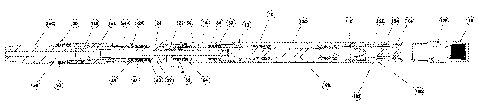
A down hole apparatus for generating a pulsing action includes a tubular housing a rotating first mandrel with a first cam profile and a reciprocating second mandrel with a second cam profile, which engages the first cam profile. Upon rotational movement of the first mandrel, the first cam profile exerts an axial force upon the second cam profile to initiate a pulsing action by forcing the second mandrel away from the first mandrel. Springs bias the second mandrel back toward the first mandrel, thereby completing the pulsing action and maintaining the second cam profile engaged with the first cam profile.


French Abstract

Un appareil de fond conçu pour générer des pulsations comprend un tubulaire qui loge un premier mandrin rotatif avec un premier profil de came et un second mandrin alternatif avec un second profil de came, lequel met en prise le premier profil de came. Lors du mouvement rotationnel du premier mandrin, le premier profil de came exerce une force axiale sur le second profil de came pour lancer une pulsation en forçant le second mandrin à séloigner du premier mandrin. Des ressorts forcent le second mandrin à revenir vers le premier mandrin, terminant ainsi la pulsation et maintenant le second profil de came en prise avec le premier profil de came.

Claims

Note: Claims are shown in the official language in which they were submitted.


6
What is Claimed is:
1. A down hole apparatus for generating a pulsing action, comprising:
a tubular housing having a first end, a second end, and an interior surface
defining an
interior bore, the interior surface of the housing having an interior axial
engagement at the
second end;
a first mandrel having a first end and a second end, the first mandrel being
journalled
for rotation within the interior bore at the first end of the housing, the
second end of the first
mandrel having a first cam profile;
a second mandrel having a first end, a second end and an exterior surface
having an
exterior axial engagement, the second mandrel being positioned within the
interior bore of the
housing with the exterior axial engagement engaged with the interior axial
engagement on the
interior surface of the housing with the second mandrel unable to rotate but
able to move
axially relative to the housing, the first end of the second mandrel having a
second cam
profile, the second cam profile engaging the first cam profile, such that upon
rotational
movement of the first mandrel the first cam profile exerts an axial force upon
the second cam
profile forcing the second mandrel away from the first mandrel; and
springs positioned between an interior shoulder on the interior surface of the
housing
and an exterior shoulder on the second mandrel to apply a force biasing the
second mandrel
toward the first mandrel, thereby maintaining the second cam profile engaged
with the first
cam profile.
2. The down hole apparatus for generating a pulsing action of Claim 1, wherein
a down
hole motor assembly is coupled to and used to impart a rotational force to the
first
mandrel, the down hole motor assembly comprising:
a moineau motor having a rotor and stator, with the rotor rotating in response
to passage of fluids through the stator; and
a universal joint used to convert eccentric rotation of a remote end of the
rotor
to concentric motion for input to the first mandrel

Description

Note: Descriptions are shown in the official language in which they were submitted.


CA 02689949 2010-01-11
TITLE
[0001] Down hole apparatus for generating a pulsing action
FIELD
[0002] There is described a down hole apparatus that generates a pulsing
action which is
transmitted to a drill bit to avoid becoming struck in a horizontal well.
BACKGROUND
[0003] U.S. Patent 6,508,317 (Eddison et al) describes a down hole apparatus
that
generates a pulsing action, which is transmitted to a drill bit to avoid
becoming stuck in a
horizontal well. The manner of generating the pulsing action is to incorporate
into the down
hole apparatus a pressure responsive device, which expands or retracts in
response to varying
flow pressure. The apparatus which will hereinafter be described generates a
similar pulsing
action using an alternative technology.
SUMMARY
[0004] There is provided a down hole apparatus for generating a pulsing
action,
including a tubular housing having a first end, a second end, and an interior
surface defining
an interior bore. The interior surface of the housing has an interior axial
engagement at the
second end. A first mandrel is provided having a first end and a second end.
The first
mandrel is journalled for rotation within the interior bore at the first end
of the housing. The
second end of the first mandrel has a first cam profile. A second mandrel is
provided having a
first end, a second end and an exterior surface having an exterior axial
engagement. The
second mandrel is positioned within the interior bore of the housing with the
exterior axial
2S engagement engaged with the interior axial engagement on the interior
surface of the housing
with the second mandrel unable to rotate but able to move axially relative to
the housing. The
first end of the second mandrel has a second cam profile, which engages the
first cam profile.
Upon rotational movement of the first mandrel, the first cam profile exerts an
axial force
upon the second cam profile forcing the second mandrel away from the first
mandrel. Springs
are positioned between an interior shoulder on the interior surface of the
housing and an
exterior shoulder on the second mandrel to apply a force biasing the second
mandrel toward
the first mandrel, thereby maintaining the second cam profile engaged with the
first cam
profile.

CA 02689949 2010-01-11
2
BRIEF DESCRIPTION OF THE DRAWINGS
[0005] These and other features will become more apparent from the following
description in which reference is made to the appended drawings, the drawings
are for the
purpose of illustration only and are not intended to be in any way limiting,
wherein:
FIG. 1 is a side elevation view, in section, of a down hole apparatus for
generating a pulsing action coupled to a down hole motor assembly.
FIG. 2 is a detailed side elevation view, in section, of the down hole
apparatus for
generating a pulsing action of FIG. 1 taken from detail A.
FIG. 3 is perspective view of an interior axial splined engagement at a second
end
of a housing component of the down hole apparatus for generating a pulsing
action of FIG. 1.
FIG. 4 is perspective view of a coupling component with an exterior axial
splined
engagement of a second mandrel of the down hole apparatus for generating a
pulsing action
of FIG. 1.
FIG. 5 is perspective view of a first cam component of the down hole apparatus
for generating a pulsing action of FIG. 1.
DETAILED DESCRIPTION
[0006] A down hole apparatus for generating a pulsing action generally
identified by
reference numeral 10, will now be described with reference to FIG 1 through
FIG 5.
Structure and Relationship of Parts:
[0007] Referring to FIG 1, down hole apparatus 10 includes a tubular housing
12, a first
mandrel 14 and a second mandrel 16.
[0008] Housing, generally indciated by refernence numeral 12, has a first end
18, a
second end 20, and an interior surface 22 defining an interior bore 24. For
ease of fabrication
and assembly, housing 12 is made up of several components: main housing 12A
and splined
housing 12B. With the preferred embodiment illustrated in FIG 1, there is also
a universal
joint housing 12C, a stator housing 12D, and a top sub housing 12E. Splined
housing 12B is

CA 02689949 2010-01-11
3
positioned at second end 20 of housing 12. Referring to FIG 3, interior
surface 22 of splined
housing 12B has an interior axial splined engagement 26.
[0009] Referring to FIG 1, first mandrel 14 has a first end 28 and a second
end 30. First
mandrel 14 is joumaled by radial bearings 32 for rotation within interior bore
24 at first end
18 of housing 12. Referring to FIG 2, second end 30 of first mandrel 14 has a
first cam
profile 34. Referring to FIG 5, first cam profile 34 is illustrated.
[0010] Referring to FIG 1, second mandrel 16 has a first end 36, a second end
38 and an
exterior surface 40. For ease of manufacture and assembly, second mandrel is
made from
several components: a main second mandrel 16A, a splined coupling mandrel 16B
and a
bottom sub mandrel 16C. Referring to FIG 4, splined coupling mandrel 16B has
an exterior
axial splined engagement 42. Referring to FIG 1, second mandrel 16 is
positioned within
interior bore 24 of housing 12 with exterior axial splined engagement 42 on
splined coupling
mandrel 16B engaged with interior axial splined engagement 26 on interior
surface 22 of
splined housing 12B. When exterior axial splined engagement 42 is engaged with
interior
axial splined engagement 26, second mandrel 16 is unable to rotate relative to
housing 12 but
able to move axially relative to housing 12. First end 36 of second mandrel 16
has a second
cam profile 44. Referring to FIG 2, first end 36 of second mandrel 16 engages
second end 30
of first mandrel 14 in mating male to female engagement. When second mandrel
16 and first
mandrel 14 are mated, second cam profile 44 engages first cam profile 34.
Second cam
profile 44 is similar to first cam profile 34 illustrated in FIG 5, and has,
therefore, not been
separately illustrated.
[00111 Referring to FIG 1 and FIG 2, upon rotational movement of first mandrel
14, first
cam profile 34 exerts an axial force upon second cam profile 44 initiating a
pulsing action by
forcing second mandrel 16 away from first mandrel 14. Belville springs 46 are
positioned
between an interior shoulder 48 on interior surface 22 of housing 12 and an
exterior shoulder
50 on second mandrel 16 to apply a force biasing second mandrel 16 back toward
first
mandrel 14, thereby completing the pulsing action and maintaining second cam
profile 44
engaged with first cam profile 34.

CA 02689949 2010-01-11
4
[0012] Referring to FIG 1, in order to facilitate axial loading on down hole
apparatus 10
thrust bearings 52 are provided which are preloaded by an upper grouping of
belville springs
54. In order to keep abrasive drilling mud away from bearings and cam
surfaces, portions of
down hole apparatus 10 are sealed with seals to form a lubricant filled
chamber 56. Seals 58
capable of withstanding relative reciprocating movement are positioned between
exterior
surface 40 at second end 38 of mandrel 16 and interior surface 22 at second
end 20 of housing
12. Referring to FIG 2, a seal 60 capable of handling rotational forces is
positioned where
rotating second end 30 of first mandrel 14 engages stationary first end 36 of
second mandrel
16. Referring to FIG 1, a pressure balancing piston 62 is provided which
carries seals 64.
Pressure balancing piston 62 moves in response to fluid pressure caused by
drilling fluids
pumped from surface. This places lubricant within chamber 56 under the same
pressure as
drilling fluids, so there is relatively less of a pressure differential for
the seals to withstand.
Pressure balancing piston also has a rotary seals 63 to seal interior of
piston 62 relative to
shaft 14.
[0013] In order for down hole apparatus to generate a pulsing action, first
mandrel 14
must be rotated. There are various ways in which this can be done. There are
down hole mud
motors, down hole turbines, and electric drive motors. In FIG 1, a preferred
configuration is
illustrated in which a down hole motor assembly, generally indicated by
reference numeral
100, is incorporated into housing 12. Down hole motor assembly 100 is coupled
to and used
to impart a rotational force to first mandrel 14. Down hole motor assembly 100
includes a
moineau motor 102 having a rotor 104 and stator 106, which is positioned
within stator
housing 12D. The operation of moineau motors is well known and will not be
further
described, except to say that rotor 104 rotates in response to passage of
fluids through stator
106. A universal joint 108, positioned in universal joint housing 12C, is used
to convert
eccentric rotation of a remote end 110 of rotor 104 to concentric motion for
input to first
mandrel 14.
Operation:
[0014] The operation of down hole apparatus 10 will now be described.
Referring to

CA 02689949 2010-01-11
FIG 1, drilling fluids pumped from surface pass into moineau motor 102 causing
rotor 104 to
rotate as the drilling fluids pass between rotor 104 and stator 106. This
results in an eccentric
rotation at remote end 110 of rotor 104. Universal joint 108 converts
eccentric rotation of
rotor 104 into concentric rotation, which concentric rotation is input into
first mandrel 14.
5 Rotation of mandrel 14 causes movement of first cam profile 34. First cam
profile 34 exerts
an axial force upon second cam profile 44 initiating a pulsing action by
forcing second
mandrel 16 away from first mandrel 14. Belville springs 46 positioned between
interior
shoulder 48 on interior surface 22 of housing 12 and exterior shoulder 50 on
second mandrel
16 apply a force biasing second mandrel 16 back toward first mandrel 14,
thereby completing
the pulsing action and maintaining second cam profile 44 engaged with first
cam profile 34.
[0015] It will be appreciated that apparatus 10 cannot be attached directly to
a drill bit.
Drill bits must rotate and apparatus 10 create a reciprocating motion, without
an
accompanying rotary motion. For this reason, apparatus 10 will normally be
used in a drilling
string in combination with a rotary turbine or a mud motor that is capable of
rotating the drill
bit.
[0016] In this patent document, the word "comprising" is used in its non-
limiting sense to
mean that items following the word are included, but items not specifically
mentioned are not
excluded. A reference to an element by the indefinite article "a" does not
exclude the
possibility that more than one of the element is present, unless the context
clearly requires that
there be one and only one of the elements.
2S [0017] The following claims are to be understood to include what is
specifically
illustrated and described above, what is conceptually equivalent, and what can
be obviously
substituted. Those skilled in the art will appreciate that various adaptations
and modifications
of the described embodiments can be configured without departing from the
scope of the
claims. The illustrated embodiments have been set forth only as examples and
should not be
taken as limiting the invention. It is to be understood that, within the scope
of the following
claims, the invention may be practiced other than as specifically illustrated
and described.

Representative Drawing
A single figure which represents the drawing illustrating the invention.
Administrative Status

2024-08-01:As part of the Next Generation Patents (NGP) transition, the Canadian Patents Database (CPD) now contains a more detailed Event History, which replicates the Event Log of our new back-office solution.

Please note that "Inactive:" events refers to events no longer in use in our new back-office solution.

For a clearer understanding of the status of the application/patent presented on this page, the site Disclaimer , as well as the definitions for Patent , Event History , Maintenance Fee  and Payment History  should be consulted.

Event History

Description Date
Time Limit for Reversal Expired 2021-08-31
Inactive: COVID 19 Update DDT19/20 Reinstatement Period End Date 2021-03-13
Letter Sent 2021-01-11
Letter Sent 2020-08-31
Inactive: COVID 19 - Deadline extended 2020-08-19
Inactive: COVID 19 - Deadline extended 2020-08-06
Inactive: COVID 19 - Deadline extended 2020-07-16
Inactive: COVID 19 - Deadline extended 2020-07-02
Letter Sent 2020-01-13
Common Representative Appointed 2019-10-30
Letter Sent 2016-07-26
Letter Sent 2015-08-17
Grant by Issuance 2015-06-09
Inactive: Cover page published 2015-06-08
Pre-grant 2015-03-12
Inactive: Final fee received 2015-03-12
Notice of Allowance is Issued 2015-02-17
Letter Sent 2015-02-17
Notice of Allowance is Issued 2015-02-17
Inactive: Approved for allowance (AFA) 2015-01-06
Inactive: Q2 passed 2015-01-06
Letter Sent 2014-03-19
Inactive: Correspondence - Transfer 2014-03-07
Inactive: Office letter 2014-02-24
Inactive: Single transfer 2014-01-30
Letter Sent 2013-12-04
Request for Examination Received 2013-12-02
Request for Examination Requirements Determined Compliant 2013-12-02
All Requirements for Examination Determined Compliant 2013-12-02
Inactive: Office letter 2013-04-02
Inactive: MF/reinstatement fee unallocated - Log 25 deleted 2013-04-02
Inactive: Delete abandonment 2013-04-02
Inactive: Correspondence - MF 2013-03-22
Deemed Abandoned - Failure to Respond to Maintenance Fee Notice 2013-01-11
Letter Sent 2012-11-09
Reinstatement Requirements Deemed Compliant for All Abandonment Reasons 2012-11-08
Deemed Abandoned - Failure to Respond to Maintenance Fee Notice 2012-01-11
Application Published (Open to Public Inspection) 2011-07-11
Inactive: Cover page published 2011-07-10
Revocation of Agent Requirements Determined Compliant 2011-04-26
Inactive: Office letter 2011-04-26
Appointment of Agent Requirements Determined Compliant 2011-04-26
Letter Sent 2011-02-08
Inactive: Single transfer 2011-01-25
Inactive: IPC assigned 2010-03-08
Inactive: First IPC assigned 2010-03-08
Inactive: IPC assigned 2010-03-08
Application Received - Regular National 2010-02-10
Inactive: Filing certificate - No RFE (English) 2010-02-10
Correct Applicant Requirements Determined Compliant 2010-02-10
Small Entity Declaration Determined Compliant 2010-01-11

Abandonment History

Abandonment Date Reason Reinstatement Date
2013-01-11
2012-01-11

Maintenance Fee

The last payment was received on 2014-12-11

Note : If the full payment has not been received on or before the date indicated, a further fee may be required which may be one of the following

  • the reinstatement fee;
  • the late payment fee; or
  • additional fee to reverse deemed expiry.

Patent fees are adjusted on the 1st of January every year. The amounts above are the current amounts if received by December 31 of the current year.
Please refer to the CIPO Patent Fees web page to see all current fee amounts.

Owners on Record

Note: Records showing the ownership history in alphabetical order.

Current Owners on Record
TERCEL IP LTD
Past Owners on Record
DAVID P. KUTINSKY
MICHAEL D. ZULAK
Past Owners that do not appear in the "Owners on Record" listing will appear in other documentation within the application.
Documents

To view selected files, please enter reCAPTCHA code :


To view images, click a link in the Document Description column (Temporarily unavailable). To download the documents, select one or more checkboxes in the first column and then click the "Download Selected in PDF format (Zip Archive)" or the "Download Selected as Single PDF" button.

List of published and non-published patent-specific documents on the CPD .

If you have any difficulty accessing content, you can call the Client Service Centre at 1-866-997-1936 or send them an e-mail at CIPO Client Service Centre.

({010=All Documents, 020=As Filed, 030=As Open to Public Inspection, 040=At Issuance, 050=Examination, 060=Incoming Correspondence, 070=Miscellaneous, 080=Outgoing Correspondence, 090=Payment})


Document
Description 
Date
(yyyy-mm-dd) 
Number of pages   Size of Image (KB) 
Description 2010-01-10 5 231
Abstract 2010-01-10 1 15
Drawings 2010-01-10 4 109
Claims 2010-01-10 1 42
Representative drawing 2011-06-07 1 20
Filing Certificate (English) 2010-02-09 1 156
Courtesy - Certificate of registration (related document(s)) 2011-02-07 1 103
Reminder of maintenance fee due 2011-09-12 1 112
Courtesy - Abandonment Letter (Maintenance Fee) 2012-03-06 1 172
Notice of Reinstatement 2012-11-08 1 164
Acknowledgement of Request for Examination 2013-12-03 1 176
Courtesy - Certificate of registration (related document(s)) 2014-03-18 1 102
Commissioner's Notice - Application Found Allowable 2015-02-16 1 161
Courtesy - Patent Term Deemed Expired 2020-09-20 1 551
Commissioner's Notice - Maintenance Fee for a Patent Not Paid 2021-02-28 1 546
Correspondence 2010-02-09 1 54
Correspondence 2011-02-07 1 23
Correspondence 2011-03-30 3 159
Correspondence 2011-04-25 1 17
Correspondence 2011-04-25 1 22
Correspondence 2013-03-21 3 188
Correspondence 2013-04-01 1 20
Correspondence 2014-02-23 1 14
Fees 2014-12-10 1 25
Correspondence 2015-03-11 1 34