Note: Descriptions are shown in the official language in which they were submitted.
CA 02690020 2010-12-09
TAE OFT IlE INVENTION: OUP ANT) LIGHTING ASSEMBLY F_QR
CAMERA SENSOR DUST DETECTION
FIELD OF THE INVENTION
The present invention relates to an assembly of a loupe and lighting means
that
can be used to enhance detection of dust particles on the sensor of digital
cameras.
BACKGROUND OF THE INVENTION
Digital cameras comprise a sensor chamber in which is lodged an electronic
sensor, such as a charge-coupled device (CCD) sensor or Complementary Metal
Oxide
Semiconductor (CMOS) sensor, onto which is projected the image of what is seen
through the
lens of the camera. This sensor can acquire the image projected thereon and
convert it into
electronic data, which is thereafter forwarded to data processing means
provided on the digital
camera. The data processing means then converts this electronic data into an
image file of
known format, such as in JPEG, TIFF or RAW formats, stored thereafter on the
memory card
of the camera. Of course, this sensor must remain as clean as possible, since
impurities
deposited thereon can undesirably alter the final image acquired by the
camera.
It is inevitable that during normal use of a digital camera, its sensor will
become exposed to the atmosphere and its airborne impurities, such as minute
airborne dust
particles. More particularly, on digital cameras having interchangeable lenses
such as digital
single-lens reflex (DSLR) cameras, the sensor inevitably becomes exposed to
the atmosphere
and its impurities whenever the lens is removed from the body of the camera,
for example
when switching lenses.
Digital camera owners have come up with a number of means to find out if
their camera's sensor is covered with contaminants before proceeding with its
cleaning. One
of them, called the f22 test, consists of shooting pictures while aiming at a
lighted backdrop
with a uniform background and consistent lighting, while the camera is set on
the longest
focal length and smallest aperture value. Then, impurities of the sensor
surface appear on the
photography as blurring spots altering the image. Consequently, this method
may require
several picture takings and computer application work to bring out the
contrast of blur spots
on the photography.
CA 02690020 2009-12-04
WO 2008/151414 2 PCT/CA2008/001068
It is noted that ordinary magnification without focused light can't help with
inspecting the camera sensor surface, since the camera sensor location is deep
within the
camera frame and ambient light reach this location only minimally. Also, the
inspection light
can't shine on the sensor directly without causing possibly irreparable
damage.
OBJECTS OF THE INVENTION
A first object of this invention is to provide an improved means to find out
if
the sensor of a digital camera is covered with dust particles.
A second object of this invention is to provide a good characterization of the
shape and/or size of the dust particles resting on the surface of a digital
camera sensor by
lighting it from different angles, instead of only relying on an overlying
light source.
SUMMARY OF THE INVENTION
The aforementioned problems are obviated by the present invention which
combines the magnification of a loupe and the reflective properties of a
configuration of
lamps whose rays shine with relatively acute incident angles instead of
shining orthogonally
to the sensor surface to detect the dust particles remaining on the digital
camera sensor
surface.
Furthermore, the configuration of lamps preferably comprises an even number
of lamps which are strategically disposed to produce a 3 dimensional effect of
the particles
remaining onto the camera sensor surface, thus enhancing detection and/or
characterization of
the dust particles. In other words, illumination of an object from an
overlying position will
end up with a diffuse halo of shade, while illumination at different angles
will generate a more
realistic form as explained in the configuration herein after. This invention
intends to make
that task quicker and more users friendly when compared to traditional means
of
accomplishing the same task like the f22 test, as described above.
The present invention thus relates to a loupe and lighting assembly for
enhancing detection of particulate contaminants on a planar surface, said
assembly
comprising a power source, a main frame body, light emitting means carried by
said frame
and operatively connected to said power source and a loupe lens also carried
by the main
frame, said light emitting means having means for generating a 3 dimensional
effect over the
particulate contaminants on the planar surface, wherein enhanced detection and
characterization of the particulate contaminants is achieved.
In one embodiment, the light emitting means consists of a number of LED
diodes arrayed peripherally of said main frame body.
CA 02690020 2009-12-04
WO 2008/151414 3 PCT/CA2008/001068
Preferably, the means for generating a 3 dimensional effect consists in each
LED diode being tilted with a small acute angle from the axis extending
orthogonally through
the plane of said main frame body, so that said diodes are focused at a common
point in space
ahead of said assembly.
The shape of said main frame body of said loupe and lighting assembly is
selected from the group comprising cylindroid shape and quadrangular shape.
The main frame body could be of cylindroid shape with said LED diodes
disposed peripherally and equidistantly within said cylindroid body.
Preferably, the LED diodes acute angle ranges between 30 to 45 degrees, and
most preferably about 30 degrees.
In another embodiment, the LED diodes are disposed in first and second
transversely spaced adjacent rows inside the cylindroid body, said LED diodes
from said first
row having a first acute angle and said LED diodes from said second row having
a second
acute angle different from said first acute angle.
In this latter embodiment, the first acute angle is preferably about 30
degrees
and said second acute angle is preferably about 45 degrees.
Each of said first row and said second row may comprise 6 LED diodes
peripherally and equidistantly disposed inside said cylindroid main frame
body.
The bottom end of said cylindroid main frame body may be shaped and sized
complementarily to a digital camera site to abuttingly fit therein.
In one embodiment, the light-emitting diodes are of an even number.
The power source is preferably an electrical battery operatively carried by
said
main frame body, said battery powering said loupe and lighting assembly and
said main frame
body comprising a sliding panel which covers said battery and insures said
battery stays in
place.
The loupe lens could have magnification capacity between 5 X and 10 X, and
preferably between 5 X and 7 X.
In another embodiment, the electromagnetic spectrum emitted by said LED
diodes is selected from the group comprising the ultraviolet range and the
infrared range of
wavelengths.
In another embodiment, the loupe lens further includes an anti-reflective
coating, preferably made of MgF2.
In another embodiment, a manual trigger switch is provided to said main frame
body and operatively connected to said power source and to said light emitting
means, said
CA 02690020 2009-12-04
WO 2008/151414 4 PCT/CA2008/001068
trigger switch enabling the user to selectively activate said loupe and
lighting assembly only
when required and thus preventing unnecessary use of said power source.
The invention also relates to a method of use of a loupe and lighting assembly
of the type comprising a battery power source, a main frame body, light
emitting means
carried by said frame and operatively connected to said power source and a
loupe lens also
carried by the main frame, said light emitting means having means for
generating a 3
dimensional effect over the particulate contaminants on the planar surface,
wherein enhanced
detection and characterization of said particulate contaminants is achieved,
said method
comprising the following steps :
a) placing camera face up on the table, with the removable lens taken off;
b) bringing loupe and lighting assembly in register with the lens socket site;
c) powering the battery power source; and
d) orienting and positioning said loupe and lighting assembly in such a
fashion as to
enable enhanced detection and characterization of dust contaminants on the
sensor.
The invention also relates to a method of use as in claim 20, further
including
step bb), occurring between step b) and step c), said step bb) consisting of
abutting a said
loupe and lighting assembly against said lens socket site.
BRIEF DESCRIPTION OF THE DRAWINGS
In the drawings illustrating the preferred embodiment of the invention;
Fig. 1 is a side view of the preferred embodiment of the loupe and lighting
assembly
according to the present invention;
Fig. 2 shows an enlarged cross-sectional view of the preferred embodiment of
Fig. 1;
Fig. 3 is a bottom plan view of the preferred embodiment;
Fig. 4 is another side view of the preferred embodiment, relative to Fig. 1;
Fig. 5 on the first sheet of drawings is yet another side view of the
preferred
embodiment, relative to Figs. 1 and 4.
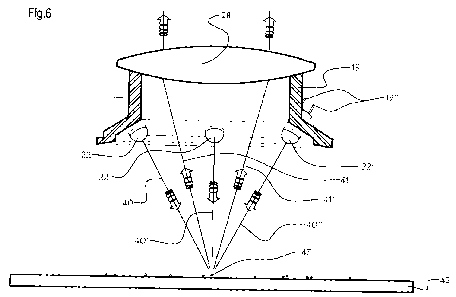
Fig. 6 is a partly broken schematic cross-sectional view similar to Fig. 2 but
at a
smaller scale, and further showing in edge view a planar sensor with dust
particles to be
detected and characterized by the present invention, the sensor at a distance
from the loupe
and lighting assembly;
Fig. 7a and 7b are two perspective views of the loupe and lighting assembly of
Fig. 1,
from two different perspectives; and
Fig. 7c is an exploded perspective view of the loupe and lighting assembly,
taken from
the perspective of Fig. 4.
CA 02690020 2009-12-04
WO 2008/151414 5 PCT/CA2008/001068
DETAILED DESCRIPTION OF THE EMBODIMENT
Figs. 1, 3-5, 7a and 7b generally show a loupe and lighting assembly for
camera
sensor dust detection 10, according to the present invention, used to enhance
detection and
characterization of particulate contaminants on a camera sensor. This loupe
and lighting
assembly comprises a hollow-centered cylindroid main frame body 12, comprising
a battery
housing 14 containing the batteries 17 needed to power the lights of the
invention and covered
by a sliding cover 18 with embossed notches providing a better grip and
enabling easier
access. Upon the main frame body 12 is also integrated a manual trigger switch
16 allowing a
selective powering of the loupe and lighting assembly and thus preventing
depletion of the
batteries 17 when the invention is not in use, with embossed notches for a
better grip. Radially
and inwardly within the cylindroid main frame body 12 is fastened a smaller
hollow-centered
cylindroid body with a conic flange 13 (better seen on Figs. 2, 6 and 7c) upon
which are
embedded a number of light-emitting diodes (LED), preferably six, which are
identified by
numbers 22, 22', 22", 22"9, 22"" and 22""' on Fig. 3 and disposed in a
peripherally,
spaced apart fashion and thus creating a LED array. Each of the diodes 22,
22', 22", 22"9,
22"" and 22""' is tilted with an acute angle, preferably between 30 to 45
degrees and most
preferably 30 degrees.
In the preferred embodiment, the cylindrical embossed shaped body 24 is carved
upon
the main frame body 12 to enable installation of the loupe and lighting
assembly for camera
sensor dust detection 10 abuttingly against the digital camera sensor site of
a digital single-
lens reflex (DSLR) camera, but the latter may alternately be used in spaced
register with the
sensor site opening. The loupe and lighting assembly 10 could also be used to
detect and
characterize particulate contaminants upon the lens of any other types of
cameras, for
example state of the art digital cameras, or other lenses in other
applications, not excluding
optical microscopy, optical and digital telescopes, spectacles lenses and
alike. The field of use
of the loupe and lighting assembly 10 is not limited to detecting impurities
upon lenses but
could also extend to any planar surfaces, although it's not the main purpose
intended.
As seen on Fig. 2, a radially inwardly curved rearward extension 30 of the
hollow-
centered cylindroid main frame body 12 is used to wedge the tapered peripheral
edge of a
biconvex loupe lens 28 in place against the cylindroid body with a forward
conic flange 13,
coplanar therewith. Both of these parts forwardly (13) and backwardly (30)
wedging the loupe
lens 28 therebetween have a slightly slanted edge where they make contact in
order for the
loupe lens 28 to frictionally interlock between them. Another transverse
extension 25 of the
hollow-centered cylindroid main frame body 12 extends inside the loupe and
lighting
CA 02690020 2009-12-04
WO 2008/151414 6 PCT/CA2008/001068
assembly 10 and further constitutes an edgewise abutment stopper for loupe
lens 28 to protect
against accidental lateral movements thereof. A forward radially outwardly
extending
protuberance 29 of the hollow-centered cylindroid body with a conic flange 13
is used to
fasten the latter to the main frame body 12 when said protuberance 29 is
inserted into an
annular notch 29a, which is carved upon the radially inward peripheral surface
of the main
frame body 12.
As said before, inside the battery housing 14 are preferably two discoid
batteries 17. Those batteries 17 are making contact with two electrodes 20 and
21 (Fig. 2).
Wires 20a and 21a of electrodes 20 and 21 project radially inwardly through
the wall of the
main frame body 12 and into the annular hollow between body extensions 13 and
30 and the
main frame body 12. Electrodes 20 and 21 enable the flow of electric current
through wires
20a and 21a. Wires 20a and 21a connect with the metallic contacts 23 of the
manual trigger
switch 16 and then to the electrodes 19, 19', 19", 19"', 19"" and 19""' of the
corresponding LED 22, 22', 22", 22"', 22"" and 22""', making a series circuit
and thus
enabling the powering of the loupe and lighting assembly for camera sensor
dust detection 10.
A parallel circuit could also be made with the diodes, thus allowing easier
detection and
replacement thereafter of dead diodes, if this situation was to happen. The
two batteries 17
used to power the series circuit may be CR2025 lithium batteries or preferably
the more
recent CR2032 Lithium batteries.
The manual trigger switch 16 is nested within and retained into a
corresponding radial orifice 16a made in main body 12 as seen on Fig. 7c which
allows it to
slide circumferentially tangentially along the side of the main frame body 12.
The manual
trigger switch 16 has a powered-off limit position, corresponding to an open
circuit and no
power circulating inside the loupe and lighting assembly for camera sensor
dust detection 10,
and a powered-on limit position, corresponding to a closed circuit and
enabling the normal
functioning of the loupe and lighting assembly 10.
Fig. 6 shows the light rays 40, 40' and 40" emitted by the LED array
comprising diodes 22, 22', 22", 22"', 22"" and 22""' when the loupe and
lighting
assembly 10 is activated by displacing the manual trigger switch 16 from the
powered-off
limit position to the powered-on limit position. Those incident rays 40, 40'
and 40" are
absorbed by the dust particle 43 resting upon the sensor surface 42 and
located at the focal
point of both the LED array comprising diodes 22, 22' and 22"and the loupe
lens 28.
Reflected rays 41 and 41' are reemitted by the dust particle 43 and passing
through the loupe
lens 28, coming out parallel to each other so an observer looking through the
loupe and
lighting assembly for camera sensor dust detection 10 witnesses an enlarged
image of this
CA 02690020 2009-12-04
WO 2008/151414 7 PCT/CA2008/001068
dust particle. The loupe lens 28 is a thick biconvex converging lens operating
like a
magnifying glass, i.e. enlarging an object seen through loupe lens 28 and
located between the
focal point of the lens and the lens itself by augmenting the apparent angle
with which the
observer is looking at the object, which is in this case the dust particle 43.
The image thereby
created is virtual and of a bigger size than the original object, thus giving
the observer the
impression that the object has been enlarged. When the object is located in
the focal plane of
the loupe lens 28, which comprises said focal point, the rays coming from the
object and
going through the lens are thereafter parallel to each other, creating a
virtual image at infinity
with a certain enlargement that is not maximum. However, in such a situation
the eye lens is
relaxed and thus looking at the enlarged object requires no accommodation, so
the observer
can stare at it for extended periods of time without tiring. The ratio of the
angle subtended by
the image when looking through the loupe lens 28 to the angle subtended by the
object when
looking at it without optical apparatus at a given distance, the "punctum
proximum", is called
angular magnification, or magnification power. This value allows the
determination of how
much bigger the object is seen when looking through the loupe lens 28. In the
case of a
magnifying glass like the loupe lens 28, the angular magnification simplifies
to the ratio of the
"punctum proximum" of the eye, which is estimated to be 25 centimeters, to the
focal length
of the lens.
The particular disposition of LED array 22, 22', 22", 22"', 22"" and 22""'
as seen on Fig. 3, allows for a 3 dimensional effect over the particles
resting on the sensor
surface 42. This way of lighting the dust particle 43 gives a better contrast
by casting a halo of
shadow around said dust particle 43 and lighting a larger area of the particle
surface, thus
putting the emphasis on the particle for an onlooking observer and realizing
the
aforementioned effect, permitting detection and characterization (size and
topographical
contour) of the dust particle 43.
Rather than being coplanar to main body 12, the loupe lens 28 could
alternately
be tilted within loupe and lighting assembly 10 with a small acute angle about
the planes of
the cylindroid main frame body 12 and cylindroid body with a conic flange 13,
however this
would require complex adjustments for the diodes to have varied angles and
orientations to
make them focus at the same focal point as the loupe lens 28. That's why it is
better for lens
28 to be coplanar within the cylindroid main frame body 12, in order for the
device to have a
certain circular symmetry around axis II as seen on Fig. 7c and thus requiring
less work
configuring the orientation of the diodes 22, 22, 22", 22"', 22"" and 22""' to
focus about
the focal point of loupe lens 28.
CA 02690020 2009-12-04
WO 2008/151414 8 PCT/CA2008/001068
In the preferred embodiment, the loupe lens 28 is positioned in such a way as
to make the entire sensor surface 42 visible through the loupe and lighting
assembly 10.
However, the bigger the magnification power is, the shorter the focal length
will need to be.
In order to comply with the two previous limitations, the operational range of
magnification
values of the loupe lens 28 comprised in the loupe and lighting assembly 10
has been found to
be between 5 X and 10 X. The loupe lens 28 of the most preferred embodiment
has an optimal
magnification power between 5 X and 7 X, allowing a good focal length when
taking into
account the position of the sensor and a magnification allowing the detection
and
characterization of particulate contaminants upon the sensor surface. Also,
the closer the focal
point is to the lens, the more the lens will be curved, resulting in more
spherical aberrations
and thus deformation of the image seen through the loupe lens 28 for higher
magnifications
through a single lens, aberrations which are to be avoided.
The loupe lens 28 is preferably made of K9 optical glass and may have a
diameter of about 50 millimeters, with an MgF2 coating to make it anti-
reflective. This
coating gives the loupe and lighting assembly 10 a better efficiency by making
more of the
incoming light transmit through the loupe lens 28, augmenting light intensity
getting to the
user's eyes passively, that is without using more powerful LED diodes which
would in turn
necessitate more battery current. It also prevents chromatic aberrations and
mildew build-up
upon the surface of the lens, as well as unwanted reflections upon the loupe
lens 28 surface,
which would make the characterization and detection of dust particle 43 less
reliable due to
these reflections parasitizing the image perceived by the observer. Light-
emitting diodes 22,
22', 22", 22"', 22"" and 22""' are preferably 5 millimeters wide and of water
clear color,
with a luminous intensity between 18000 and 20000 mcd (milli-candela). In the
preferred
embodiment, the main frame body 12, the smaller cylindroid body with a conic
flange 13, the
battery housing 14, the sliding cover 18 and the manual trigger switch 16 are
made out of
acrylonitrile butadiene styrene (ABS) plastic because of its qualities
(rigidity, moldability,
availability, toughness and low cost). Once dust particles are detected upon
the sensor surface,
a swab can be used to remove them without damaging the filter coating of the
sensor, for
example an anti-smear cleaning swab with perforated blade as disclosed in
applicant's
publication No. WO 2007/112550 Al published October 11, 2007.