Note: Descriptions are shown in the official language in which they were submitted.
CA 02690230 2009-12-08
WO 2009/006042 PCT/US2008/067611
EJECTOR DRILL SYSTEM
BACKGROUND AND SUMMARY OF THE DISCLOSURE
[0001] Certain deep hole drilling systenis such as gun drills, single tube di-
illing systems, and
double tube drilling systems are known in the art. These deep hole drilling
systems may be used
for drilling holes with a large depth to diameter ratio.
[0002] A single tube system, or STS drilling system may be used to drill holes
having large
depth to diameter ratios with improved penetration rates, hole size accuracy,
and straightness
over gun drills. At the same time, such systems have various disadvantages,
such as tending to
cut on themselves, due to a single effective cutting edge. This causes
significant stresses.
Additionally, such systems nlay utilize a wear pad, which due to the
configuration, tends to bear
on the sides of the formed hole dtuing cutting with significant force, such
that the wear pad tends
to cause hardening of the hole and embrittlement of the material. This may be
termed work
hardening of the hole, wliich is undesirable. The STS drilling system may
include a drilling head,
a boring shank, or tube, and a pressure head. The drilling head may be
threaded onto the tube, the
inside of the tube being in commtuzication with one or more apertures through
the drilling head.
In operation, the pressure head may force cutting fluid between the outside of
the tube and the
hole wall. The cutting fluid may be evacuated along with chips created by the
drilling process
through the drilling head and up through the center of the tube.
100031 The STS requires a cutting fluid delivery system for providing a volume
of cutting
fluid at pressures of up to 1000 pounds per square inch (about 689.4
kilopascals) or more. The
pressure head introduces ctitting fluid between the tube and the hole wall. To
maintain pressure
in the cavity, the pressure head may seal against the part being drilled to
produce a water tight
seal. In one scaling embodimeiit, the part being drilled may liave a flat area
around the drilled
llole for the pressure head to seal.
[0004] A Double Tube System, or DTS drilling system, also lazown as an Ejector
System, is
based on sinlilar principles as the Single Tube System. Both systems may
utilize a cylindrical
body design and evacuate ctitting fluid and chips internally, The DTS system
niay use less
cutting fluid pressure and volumea
CA 02690230 2009-12-08
WO 2009/006042 PCT/US2008/067611
2
[0005] The DTS drilling system may include a drilling head, an outer tube, an
inner tube, and
a rotating or non-rotating machine connection. The drilling head may be thi-
eaded onto the outer
tube, witli the inner tube in communication with one or more apertures through
the drilling head.
Both the inner and outer tubes are retained by the machine tool connector,
Cutting fluid is
chaimeled through the machine tool connector and between the outer tube and
the irmer tube. A
portion of the cutting fluid is directed internally into the inner tube
through ventlu-i slots
manufactured into the inner tube wall. The remaining cutting fluid proceeds to
the cutting edge
in order to cool and lubricate the tool. The cutting fluid diverted through
the venturi slots creates
a low pressure area in the inner tube drawing cutting fluid and cllips from
the cutting edge
tlirough the drilling head and into the inner tube. This vacuum-like phenomena
may reduce the
amount of cutting fluid pressure and volume by up to 50% or more, Certain DTS
system
embodiments may be used for holes that are about 0.75 inches (about 19
millimeters) in diameter
or larger.
[00061 The drilling heads for STS and DTS drilling systems niay comprise a
tlireaded tool
body with chip evacuation inlet apertures, one or more cutting eciges, and one
or more wear pads,
The cutting edges in the prior art have included hardened steel cutting edges
or a plurality of
inserts. Drilling heads in the prior art contain cutting edges that are
difficult to replace or re-
sharpen, and are discarded after the cutting edges are worn.
[0007] There remains a need for STS and DTS drilling systems to overcome these
and other
disadvantages of the prior art.
[0008] A drilling head according to an example of the present invention is
disclosed for a
tubulai- shank having an inside diameter and threads comprising an axial body
having a duct
exiting througli a first end. Threads adjacent the first end corresponding to
the threads on the
shank align the duct with the shank inside diameter. A bore is provided from
an outer surface of
the body to ttie duct; and two axially extending approximately parallel and
offset surfaces
adjacent a second end. An insert is affixed between the offset surfaces, the
insert comprising: a
first face at least partially contacting one offset surface and a second face
at least partially
contacting the other offset surface; one or more cutting edges adjacent the
first face, the second
face, or botli; and a cutting lip adjacent one or more cutting edges.
CA 02690230 2009-12-08
WO 2009/006042 PCT/US2008/067611
3
BRIEF DESCRIPTION OF THE DRAWINGS
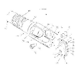
[0009] FIG. I is an exploded perspective view of a drilling head of the
present disclosure;
[0010] FIG. 2 is a side elevational view of the drilling head of FIG. 1;
100111 FIG. 3 is a perspective view of the drilling head of FIG. 1;
[0012] FIG. 4 is a perspective view of the drilling head of FIG. 1 including
carbide cladding;
[0013] FIG. 5 is a perspective view of the drilling head of FIG. I inclhading
carbide wear
pads ;
[0014] FIG. 6 is a perspective view of another embodiment of a drilling head
of the present
disclosure; and
[0015] FIG. 7 is a perspective view of yet another embodiment of a drilling
head of the
present disclosure.
DETAILED DESCRIPTION OF THE DRAWINGS
[0016] Referring now to FIG. 1-7, examples of a drilling system according to
the invention
are set forth. In FIGS. 1-5, an example of the drilling system is shown,
having a drilling head 10
which may comprise an ejector holder body 12 and at least one cutting insert
14. The cutting
insert 14 niay be, for exan7ple but not limited to, a spade insert. Any
suitable cutting insert 14
may be used in the ejector holder body 12. In operation, the ejector holder
body 12 and cutting
insert 14 rotate about an axis of rotation through the centerline of the hole
being drilled.
[0017] As shown in FIG. 1, the cutting insert 14 may be a spade insert having
an
approximately flat polygonal shape having a first face 15, a second face 16, a
first side 17, and a
second side 18. The cutting insert may comprise one or more mounting apertures
19 through the
first and second faces 15, 16. The cutting insert may further comprise a self-
centering point 20,
cutting edges 22, cutting lip 24, web cutting edges 23, cutting web 26, and
optionally one or
more chip bi-ealcers 28.
[0018] The cutting insert 14 niay iilclude cutting edges 22, The cutting edges
22 may be
positioned at the leading edges as the insei-t rotates. The cutting insert 14
may be an
approximately synunetrical shape with the axis of rotation passing through the
self-centering
point 20, In this embodiment, the insert may have cutting edges 22 on both
sides of the insert.
CA 02690230 2009-12-08
WO 2009/006042 PCT/US2008/067611
4
The cutting edges 22 may extend about from the web cutting edges 23 around
self centering
point 20 toward the first side 17 adjacent the first face 15, from the self
centering point 20
toward the second side 18 adjacent the second face 16, or botli. Any number of
cutting edges
may be provided for making a desired hole diameter.
[0019] At least one cutting lip 24 may be positioned adjacent one or more
cutting edges 22.
The cutting lip 24 may include geometry capable of producing a curled metal
chip for evacuating
through the ejector holder body 12. The size and shape of the chip may be
controlled by altering
the cutting lip 24 position, size and configuration.
[0020] At least one cutting web 26 may be positioned adjacent the self-
eentering point 20,
and the cutting web 26 may comprise one or more web cutting edges 23. The
cutting web 26
may enable the material at the tip of the cutting insert 14 to shear and form
a manageable chip.
Some prior art drilling systems do not mechanically cut niaterial (chip
formation) at the center of
the drilled hole, instead extruding material due to the low angular velocity
at the center of the
drill point. The cutting web 26 may enable chip formation at the dr-ill point
and reduce extrusion
due to the shearing ability of the cutting web 26. Further, the cutting web 26
may enable the drill
cutting insert 14 to stai-t the hole on-center and retain its straightness.
100211 One or more chip breakers 28 may be optionally provided on the cutting
insert 14 to
control the chip width. Controlling the chip width further enables the chip to
be evaciiated
through the center of the ejector holder body 12. hi some applications, chip
breakers may not be
required, for example with use in cutting cast iron or carbon fibers.
[0022] The ejector holder body 12 may comprise a generally tubular shape
liaving a first end,
or shank end 36, and a second end, or insert end 34. An evacuation channel, or
duct 38 th.rough
at least a portion of the ejector holder body 12 may exit the shank end 36 for
passing chips and
cutting fluici through the ejector holder body 12 and into the shank, or tube.
The shank end 36
may be configured to attacli to a boring shank, or tube, (not shown). "The
tube may have an inside
diameter and threads for attaching the drilling head. The ejector holder body
12 may comprise
threads 40 adjacent the fii-st end, or shank end 36, corresponcling to the
threads on the shank and
aligning the duct 38 with the shank, or tube, inside diameter. The duct 38
does not have to be the
same diameter as the inside diameter of the tube when the duct and tube are
aligned.
[0023] The threads 40 may be multiple lead locking threads. Alternately, the
threads 40 may
be a single leaci thread.
CA 02690230 2009-12-08
WO 2009/006042 PCT/US2008/067611
[00241 A tube bearing surface 42 may be provided on the ejector holder body 12
adjacent the
intersection of the tube and the ejector holder body 12. The tube bearing
surface 42 may fit
within an inside diameter of the tube and fit adjacent an inside surface of
the tube. The tube
bearing surface 42 may be used to align the ejector holder body 12 with the
ttibe. The tube
bearing surface may be precision ground to mate closely with the inside
surface of the tube. A
close tolerance fit may reduce total indicator run-out associated with the
ejector drilling system
and improve hole straightness,
[0025] The threads 40 or the tube bearing surface 42 or a combination thereof
may be
designed to substantially seal the union between the tube and the ejector
holder body 12. Otller
sealing devices or methods may be utilized, such as for example but not
limited to one or more
o-rings, gaskets, sealing tapes, caulking materials, adhesives, or other
sealing materials.
[0026] The boring shanlc, or tube, may be provided with threads on the inside
surface
corresponding to the threads 40 of the ejector holder body 12. The inside tube
threads may be
locking threads that draw the threads 40 tighter into the tube as the drilling
system is rotated in
operation.
[0027] Alternately, the ejector holder body 12 may attach to the boring shank,
or tube, by
other attach.nients, such as for example but not limited to one or more
keyways, clanlps, flanges,
screws, or other fasteners.
[0028] The insert end 34 may be configured for attaching the cutting insert
14. The insert end
34 may be configured with two axially extending approximately parallel and
offset surfaces 30,
32 adjacent a second end. The surfaces 30, 32 may be offset a distance equal
to the thickness of
the insert 14. The surfaces 30, 32 may also be offset in a longitudinal
direction to provide
clearance for fastening the insert 14 to the body 12. The cutting insei-t 14
may attach to the insert
end 34 with the first face 15 at least partially contacting one offset surface
30 and the second f'ace
16 at least partially contacting the other offset surface 32 by one or more
screws 43 through the
mouiiting apertures 19 of the cutting insert 14.
[0029] The ejector holder body 12 may comprise a bearing area 44. The bearing
area 44 may
include one or more outer surfaces of the ejector holder body 12. The bearing
area 44 may have a
layer of chi-ome to protect the bearing area 44 in operation. The outer
diameter of the bearing
area 44 may be sliglitly smaller than drill diameter. The chrome layer may
protect the bearing
area 44 at lower rotational speeds and temperatures.
CA 02690230 2009-12-08
WO 2009/006042 PCT/iTS2008/067611
6
(0030] As shown in FIGS. 4 and 5, the bearing area 44 may comprise a cladding
46 on at
least a portion of the outer surface of the body. The cladding 46 may comprise
a thin layer of a
carbide material on the surface positioned at an outside diameter of the body.
The outer diameter
of the cladding 46 may be slightly smaller than drill diameter. The cladding
46 may protect the
bearing area 44 at higher rotational speeds and temperatures. In the example
of FIG. 5, there are
provided a plurality of carbide wear pads 46' as an alternative embodiinent.
The wear pads 46'
may be bi-azed into position or otherwise suitably secured. The thickness of
the cladding 46 or
wear pads 46' nlay be increased as suitable for the application. The cladding
46 and wear pads
46' may be formed of a carbide material, such as titanium carbide, a tungsten
carbide, aluminum
bronze, high speed steel, hard chroming or other suitable wear material.
100311 As showra in the example of FIG. 3, a channel 48 may be placed along
the outer
surface of the ejector holder body 12 capable of directing fluid toward the
insert. The channel 48
may enable cutting fluid to flow along the perimeter of the ejector holder
body 12 toward the
cutting insert 14, as shown in FIG. 3. The channel 48 may be approximately
parallel to an axis
tlirough the ejector holder body 12. The channel 48 may be approximately
parallel to an axis of
rotation of the drilling head. Alternately, the channe148 may be directed in
an angled orientation,
spiral orientation, arcuate orientation, or any other orientation capable of
directing the cutting
fluid toward the insert, The cutting fluid passing through the drilling system
may act as a coolant
for cooling the material being sheared in the cutting area to promote
manageable chip formation.
The cutting fluid also flushes the chips from the cutting area and evacuates
the chips from the
drilled hole. The coolant channels placed axially along the holder body 12
allow coolant to flow
foi-ward from the coolant tube, along the perimeter of the holder body 12 and
be directed at the
cutting zone of the insert 14. the coolant fluid quenches the material being
sheared in the cutting
zone and provides coolant flow in the direction for the formed chips to travel
from the cutting
zone to the evacuation cross hole and channel described below, and through the
coolant tube and
out of the machining center.
[00321 The ejector holder body 12 further comprises one or more cross holes,
or bores 50
passing :from one or more gullets 52 to the evacuation channel, or duct 38.
The gullets 52 provide
a passage for chips and cutting fluid from the cutting insert 14 to the bores
50. Relief areas 54
may be provided adjacent the bores 50 for directing chips and cutting fluid
into the bores and
reducing the chips collecting in the gullets 52,
CA 02690230 2009-12-08
WO 2009/006042 PCT/US2008/067611
7
[0033] In an example, the evacuation cross hole 50 passes through both gullets
52
approximately normal to the center axis of the holder body 12. Alternately,
the bores 50 may
pass through ejector holder body 12 at an angle to the axis of the ejector
holder body 12. The
bores 50 enable the chips and cutting fluid flushed from the cutting area to
enter the duct 38.
[0034] The duct 38 may extend through the ejector holder body 12 between the
shank end 36
and the bores 50, The chips that are evacuated from the cutting area may be
flushed along the
gullets 52, through the bores 50 and into the duct 38. The chips and cutting
fluid from the drilled
hole are flushed through the duct 38 and into the boring shank, or tube, From
there the cutting
fluid and chips flow through the tube and out of the machining center.
[0035] In operation, when the cutting edges 22 have reached their expected
life, the cutting
inserts 14 can be removed fronl the ejector holder body 12 by removing screws
43 and removing
the inserts. A new cutting insert 14 may be installed and the drilling process
continued.
[0036] The drilling head 10 may be used with Single Tube or Double Tube
Systems. The
disclosed drilling head 10 has advantages over the existing drill systems.
Firstly, the substrate,
coating, and geometry options nlay allow for this tool 10 to function in
applications where prior
art drills fail. The substrate material of the cutting insert 14 may be
changed to acconuz7odate
differcnt types of applications. Also, differ-ent coatings may be usable in
association with the
insert 14. For example, a diamond film coating may be used on the cutting
surfaces and
clearance surfaces of insert 14 to miniinize flank wear growth. Examples of
these types of films
include carbon vapor deposition (CVD) polycrystalline diamond film which is
well laiown in the
industry. Diamond film coatings are especially helpful when cutting non-
metallic abrasive
materials for example. Other coating materials, such as titanium aluminum
nitride, may be used.
The insert 14 may be coated by known suitable methods, with a desired coating
based upon a
particular application for the tool 10. The use of insert 14 also al lows the
cutting geometry to be
formed for various applications, with various modifications in cutting
geometry possible to
errhance the cutting performance for different applications or materials. For
example, different
cutting geometries may include, but are not limited to, the cutting lip
geometry having a positive
rake angle, the cutting web having a positive rake angle, the insert 14 having
a self-centering
point, and/or providing a desired chip breaking configuration in association
with the cutting
edges. Positive cutting lip geometry produces a tightly curled chip that is
easy to evacuate
through the tool, with the compact size of the chip resulting from the
predetermined lip position,
CA 02690230 2009-12-08
WO 2009/006042 PCT/US2008/067611
8
size and configuration. Many modifications can be made to the lip
configuration to enhance the
development of chip formation for example. The use of a positive cutting web
geometry allows
the material at the point of insert 14 to shear and form a more manageable
chip, which can
minimize the action of extruding material at the center of the drilled hole
due to the low velocity
differential at the center of the drill point. The web geometry can thus be
configured to allow for
much more mechanical chip formation at this location of the drill point, and
resul.t in less
extrusion due to the shearing ability of the web cutting edge, and a freer
cutting drill center. This
also can provide the benefit of drilling a hole that starts on center and
retains an improved overall
straightness. A self-centering point geometry niay be provided by a
combination of clearance
features on the point of the insert 14 that improve the centering capability.
Improving the
centering capability can improve the drilling stability and overall hole
straightness. The addition
of chip breakers can control the developing chip width, thereby assisting in
creating a formable
chip that can be evacuated through the center of the holder body as will be
desci-ibed.
[00371 A second advantage with the disclosed drilling head 10 is a reduction
in cost per hole.
This may be realized in several different ways. The brazed drill heads in the
prior art are a one
piece design. When the tool is worn out or damaged the entire drill head must
be replaced. This
can be costly, especially as the hole diameter increases. With the presently
disclosed drilling
head 10, an operator may replace the worn or damaged cutting insert 14. The
drilling liead 10
thus provides the ability to quickly and efficiently change the cutting edges
when they become
worn. The cost of the ejector holder body 12 may be amortized over multiple
cutting insert 14
changes reducing the total tool cost.
[0038] The cost per hole can also be calculated based on an increased
penetration rate. The
presently disclosed drilling head 10 may include two effective cutting edges.
This design can
offer a significant performance advantage over the prior art having a single
cutting edge. With
two effective cutting edges presently disclosed drilling head 10 could double
the feed rate of a
comparable single cutting edge design. This increased penetration rate reduces
the time in the cut
freeing up machine time. The arrangement according to the examples of the
present invention
provides various advantages and overcomes probleins associated with prior
systems. For
example, the arrangement does not result in work hardening or the mat-erials
adjacent the hole, as
no significant forces are imposeci on the sides ol' the formed hole. The
system does not cut on
itself as with prior STS systems, and the wear pad does bear against the hole
with excessivc
CA 02690230 2009-12-08
WO 2009/006042 PCT/US2008/067611
9
force, as there are two effective cutting edges in the system. The cutting
geometry provides for
an included angle such that radial loads imposed by the system are minimal,
and heat generation
is also mininvzed, such that no enibrittlenlent of the machined material
occurs.
[00391 An alternate example of the invention is shown in FIG, 6, wherein the
ejector holder
body 112 niay also comprise a generally tubular shape having a first end, or
shank end 136, and a
second end, or insert end having an insert 214 as in the prior examples. The
holder body 112 may
again have an evacuation chamiel, or duct through at least a portion of the
ejector holder body
1 l2 which may exit the shank end for passing chips and cutting fluid tlirough
the ejector holder
body 112 and into the shank, or tube. The shank end 136 may be configured to
attach to a boring
shanl<, or tube, (not shown). 'T'he tube may have an inside diameter and
internal threads 140 for
attaching the drilling head. The ejector holder body 112 may comprise threads
140 adjacent the
first end, or shank end 136, corresponding to the threads on the shank and
aligning the duct 138
with the shank, or tube, inside diameter. The duct 38 does not have to be the
same diametei- as
the inside diameter of the tube when the duct and tube are aligned. The
threads 140 may be
multiple lead locking threads. Alternately, the threads 140 may be a single
lead thread.
100401 A further example is shown in FIG. 7, wherein the ejector holder body
212 may again
comprise a generally tubular shape having a first end, or shank end, and a
second end, or insert
end. An evacuation channel, or duct is again provided through at least a
portion of the ejector
lioldei- body 212 and exits the shank end for passing chips and cutting tluid
through the ejector
holder body 212 and into the shank, or tube. The shai-ik end may be configured
to attach to a
boiing shank, or coolant tube, (not shown). The tube may have an inside
diameter and threads for
attaching the drilling head. The ejector holder body 212 may comprise threads
240 adjacent the
first end, or shank end, corresponding to the threads on the shank and
aligning the duct with the
shank, or tube, inside diameter, as in prior examples. The threads 240 may be
multiple lead
locking threads, or alternately, may be a single lead thread. A tube bearing
surface 242 may be
provided on the ejector holder body 212 adjacent the intersection of the tube
or shank and the
ejector holder body 212. The tube bearing surface 242 may fit within an inside
diameter of the
tube and fit adjacent an inside surface of the tube. The tube bearing surface
242 may be used to
align the ejector holder body 212 with the coolant tube. The tube bearing
surface may be
precision ground to nlate closely with the inside surface of the tube. A close
tolerance fit may
reduce total indicator run-out associated with the ejector drilling system and
improve hole
CA 02690230 2009-12-08
WO 2009/006042 PCT/US2008/067611
straightness. The boring shank, or tube, may be provided with threads on the
inside surface
corresponding to the threads 240 of the ejector holder body 212. The inside
tube threads may be
multiple lead locking threads that draw the thr-eads 240 tighter into the tube
as the drilling system
is rotated in operation, and installs the holder body 12 to the coolant tube
securely.
[0041] The ejector holder body 212 may comprise a bearing area 244. The
bearing area 244
may include one or more outer surfaces of the ejector holder body 212. The
bearing area 244
may have a layer of cl7rome or other wear material to protect the bearing area
244 in operation.
The chrome or other wear material serves to help protect the holder outside
diameter as it guides
the drill 10. The outer diameter of the bearing area 244 may be slightly
smaller than drill
diameter. The chrome layer may protect the bearing area 244 at lower
rotational speeds and
temperatures. For higher speed operation, a carbide clad material may be used
in association with
the bearing surface 244. Additionally, carbide wear strips 246 may be used to
protect the ejector
liol.der body 212. The carbide wear strips 246 may be provided in association
with the bearing
area 244. The wear strips 246 are provided on at least a portion of the outer
surface of the body,
and nlay comprise a thin strip of a carbide material on the surface positioned
at an outside
diameter of the body. The outer diameter of the strips 246 may be slightly
smaller than drill
diameter. The wear strips 246 may protect the bearing area 244 at higher
rotational speeds and
temperatures. The wear strips 246 may be brazed into position or otherwise
suitably secured to
the llolder body 212. Alternatively, the wear strips 246 may be bolted in oi-
otherwise suitably
connected to the holder body 212. The wear strips 246 may be produced using
carbide beading,
but other suitable approaches are contemplated. The thickness of the wear
strips 246 may be
increased/decreased as suitable for the application. The wear strips 246 may
be fornled of a
carbide tnatcrial, such as titanium carbide, a tungsten carbide, aluminum
bronze, high speed
steel, hard chroming or other suitable weai- material. A channel 248 may be
placed along the
outer surface of the ejector holder body 212 capable of directing fluid toward
the insert 214. The
channel 248 may enable cutting fluid to flow along the perimeter of the
ejector holder body 212
toward the cutting insert 214.
[0042] While the invention has been illustrated and described in detail in the
foregoing
drawings and description, the same is to be considered as illustrative and not
restrictive in
character, it being understood that only illustrative embodiments thereof have
been shown and
described, and that all changes and modifications that come within the spirit
of the invention
CA 02690230 2009-12-08
WO 2009/006042 PCT/US2008/067611
11
described by the following claims are desired to be protecteci. Additional
features of the
invention will become apparent to those skilled in the art upon consideration
of the description.
Modifications may be made without departing from the spirit and scope of the
invention.