Note: Descriptions are shown in the official language in which they were submitted.
CA 02690289 2013-11-13
APPLICATION FOR PATENT
TITLE: SUBSEA INTERNAL RISER ROTATING CONTROL DEVICE
SYSTEM AND METHOD
SPECIFICATION
STATEMENT REGARDING FEDERALLY SPONSORED RESEARCH OR
DEVELOPMENT
[0002] N/A
REFERENCE TO MICROFICHE APPENDIX
100931 N/A
BACKGROUND OF THE INVENTION
[0004] BACKGROUND OF THE INVENTION
[0005] I. Field of the Invention
[0006] This invention generally relates to subsea drilling system and
method, and in
particular to a system and method adapted for use with a rotating control
device (RCD) to
sealably control fluid flow in a riser.
[0007] 2. Description of Related Art
CA 02690289 2010-01-14
[0008] Marine risers extending from a wellhead fixed on the floor of an ocean
have been
used to circulate drilling fluid back to a structure or rig. The riser must be
large enough in
internal diameter to accommodate the largest bit and pipe that will be used in
drilling a
borehole into the floor of the ocean.
100091 An example of a marine riser and some of the associated drilling
components is
proposed in U.S. Pat. Nos. 4,626,135 and 7,258,171. As shown in Figure 1 of
the '171
patent, since the riser R is fixedly connected between a floating structure or
rig S and the
wellhead W, a conventional slip or telescopic joint SJ, comprising an outer
barrel OB and an
inner barrel IB with a pressure seal therebetween, is used to compensate for
the relative
vertical movement or heave between the floating rig and the fixed riser. A
diverter D has
been connected between the top inner barrel TB of the slip joint SJ and the
floating structure
or rig S to control gas accumulations in the marine riser R or low pressure
formation gas from
venting to the rig floor F. A ball joint BJ above the diverter D compensates
for other relative
movement (horizontal and rotational) or pitch and roll of the floating
structure S and the fixed
riser R.
[00010] The diverter D can use a rigid diverter line DL extending radially
outwardly from
the side of the diverter housing to communicate drilling fluid or mud from the
riser R to a
2
699012 8/SPFV65501/0064/122109
CA 02690289 2010-01-14
choke manifold CM, shale shaker SS or other drilling fluid receiving device.
Above the
diverter D is the rigid flow line RF, configured to communicate with the mud
pit MP. If the
drilling fluid is open to atmospheric pressure at the bell-nipple in the rig
floor F, the desired
drilling fluid receiving device must be limited by an equal height or level on
the structure S
or, if desired, pumped by a pump to a higher level. While the shale shaker SS
and mud pits
MP are shown schematically in Figure 1 of the '171 patent, if a bell-nipple
were at the rig
floor F level and the mud return system was under minimal operating pressure,
these fluid
receiving devices may have to be located at a level below the rig floor F for
proper operation.
Since the choke manifold CM and separator MB are used when the well is
circulated under
pressure, they do not need to be below the bell nipple.
1000111 As also shown in Figure 1 of the '171 patent, a conventional flexible
choke line CL
has been configured to communicate with choke manifold CM. The drilling fluid
then can
flow from the choke manifold CM to a mud-gas buster or separator MB and a
flare line (not
shown). The drilling fluid can then be discharged to a shale shaker SS, and
mud pits MP. In
addition to a choke line CL and kill line KL, a booster line BL can be used.
[00012] In the past, when drilling in deepwater with a marine riser, the riser
has not been
pressurized by mechanical devices during normal operations. The only pressure
induced by
3
699012 8/SPH/65501/0064/122109
CA 02690289 2010-01-14
the rig operator and contained by the riser is that generated by the density
of the drilling mud
held in the riser (hydrostatic pressure). During some operations, gas can
unintentionally enter
the riser from the wellbore. If this happens, the gas will move up the riser
and expand. As
the gas expands, it will displace mud, and the riser will "unload." This
unloading process can
be quite violent and can pose a significant fire risk when gas reaches the
surface of the
floating structure via the bell-nipple at the rig floor F. As discussed above,
the riser diverter
D, as shown in Figure 1 of the '171 patent, is intended to convey this mud and
gas away from
the rig floor F when activated. However, diverters are not used during normal
drilling
operations and are generally only activated when indications of gas in the
riser are observed.
The '135 patent proposed a gas handler annular blowout preventer GH, such as
shown in
Figure 1 of the '171 patent, to be installed in the riser R below the riser
slip joint Si. Like the
conventional diverter D, the gas handler annular blowout preventer GH is
activated only
when needed, but instead of simply providing a safe flow path for mud and gas
away from
the rig floor F, the gas handler annular blowout provider GH can be used to
hold limited
pressure on the riser R and control the riser unloading process. An auxiliary
choke line ACL
is used to circulate mud from the riser R via the gas handler annular blowout
preventer GH to
a choke manifold CM on the rig.
4
699012 8/SPH/65501/0064/122109
CA 02690289 2010-01-14
[00013] More recently, the advantages of using underbalanced drilling,
particularly in
mature geological deepwater environments, have become known. Deepwater is
generally
considered to be between 3,000 to 7,500 feet deep and ultra deepwater is
generally
considered to be 7,500 to 10,000 feet deep. Rotating control heads or devices
(RCD's), such
as disclosed in U.S. Pat. No. 5,662,181, have provided a dependable seal
between a rotating
pipe and the riser while drilling operations are being conducted. U.S. Pat.
No. 6,138,774,
entitled "Method and Apparatus for Drilling a Borehole into a Subsea Abnormal
Pore
Pressure Environment," proposes the use of a RCD for overbalanced drilling of
a borehole
through subsea geological formations. That is, the fluid pressure inside of
the borehole is
maintained equal to or greater than the pore pressure in the surrounding
geological
formations using a fluid that is of insufficient density to generate a
borehole pressure greater
than the surrounding geological formation's pore pressures without
pressurization of the
borehole fluid. U.S. Pat. No. 6,263,982 proposes an underbalanced drilling
concept of using
a RCD to seal a marine riser while drilling in the floor of an ocean using a
rotatable pipe from
a floating structure. Additionally, U.S. Provisional Application No.
60/122,350, filed
March 2, 1999, entitled "Concepts for the Application of Rotating Control Head
Technology
to Deepwater Drilling Operations" proposes use of a RCD in deepwater drilling.
699012 8/SPH/65501/0064/122 109
_ .
CA 02690289 2010-01-14
[00014] It has also been known in the past to use a dual density mud system to
control
formations exposed in the open borehole. See Feasibility Study of a Dual
Density Mud
System for Deepwater Drilling Operations by Clovis A. Lopes and Adam T.
Bourgoyne, Jr.,
1997 Offshore Technology Conference. As a high density mud is circulated from
the
ocean floor back to the rig, gas is proposed in this May of 1997 paper to be
injected into the
mud column at or near the ocean floor to lower the mud density. However,
hydrostatic
control of abnormal formation pressure is proposed to be maintained by a
weighted mud
system that is not gas-cut below the ocean floor. Such a dual density mud
system is proposed
to reduce drilling costs by reducing the number of casing strings required to
drill the well and
by reducing the diameter requirements of the marine riser and subsea blowout
preventers.
This dual density mud system is similar to a mud nitrification system, where
nitrogen is used
to lower mud density, in that formation fluid is not necessarily produced
during the drilling
process.
[00015] As proposed in U.S. Pat. No. 4,813,495, a subsea RCD has been proposed
as an
alternative to the conventional drilling system and method when used in
conjunction with a
subsea pump that returns the drilling fluid to a drilling vessel. Since the
drilling fluid is
returned to the drilling vessel, a fluid with additives may economically be
used for
6
699012 8/SPH/65501/0064,122109
CA 02690289 2010-01-14
continuous drilling operations. ('495 patent, col. 6, In. 15 to col. 7, In.
24) Therefore, the
'495 patent moves the base line for measuring pressure gradient from the sea
surface to the
mudline of the sea floor ('495 patent, col. 1, Ins. 31-34). This change in
positioning of the
base line removes the weight of the drilling fluid or hydrostatic pressure
contained in a
conventional riser from the formation. This objective is achieved by taking
the fluid or mud
returns at the mudline and pumping them to the surface rather than requiring
the mud returns
to be forced upward through the riser by the downward pressure of the mud
column ('495
patent, col. 1, Ins. 35-40).
[00016] Conventional RCD assemblies have been sealed with a subsea housing
using active
sealing mechanisms in the subsea housing. Additionally, conventional RCD
assemblies, such
as proposed by U.S. Pat. No. 6,230,824, have used powered latching mechanisms
in the
subsea housing to position the RCD.
[00017] Additionally, the use of a RCD assembly in a dual-density drilling
operation can
incur problems caused by excess pressure in either one of the two fluids. The
ability to
relieve excess pressure in either fluid would provide safety and environmental
improvements.
For example, if a return line to a subsea mud pump plugs while mud is being
pumped into the
borehole, an overpressure situation could cause a blowout of the borehole.
Because dual-
7
699012 8/SP11/65501/0064/122109
CA 02690289 2010-01-14
density drilling can involve varying pressure differentials, an adjustable
overpressure relief
technique has been desired.
1000181 Another problem with conventional drilling techniques is that moving
of a RCD
within the marine riser by tripping in hole (T1H) or pulling out of hole
(POOH) can cause
undesirable surging or swabbing effects, respectively, within the well.
Further, in the case of
problems within the well, a desirable mechanism should provide a "fail safe"
feature to allow
removal of the RCD upon application of a predetermined force.
[00019] U.S. Pat. Nos. 6,470,975; 7,159,669; and 7,258,171 propose positioning
an RCD
assembly in a housing positioned in a marine riser. In the '171 patent, a
system and method
are disclosed for drilling in the floor of an ocean using a rotatable pipe.
The system uses a
RCD with a bearing assembly and a holding member for removably positioning the
bearing
assembly in a subsea housing. The bearing assembly is sealed with the subsea
housing by a
seal, providing a barrier between two different fluid densities. The holding
member resists
movement of the bearing assembly relative to the subsea housing. The bearing
assembly is
proposed to be connected with the subsea housing above or below the seal.
[00020] In one embodiment of the '171 patent, the holding member rotationally
engages
and disengages a passive internal formation of the subsea housing. In another
embodiment of
8
699012 8/SPH/65501/0064/122109
CA 02690289 2010-01-14
the '171 patent, the holding member engages the internal formation, disposed
between two
spaced apart side openings in the subsea housing, without regard to the
rotational position of
the holding member. The holding member of the '171 patent is configured to
release at
predetermined force.
[00021] The holding member assembly of the '171 patent provides an internal
housing
concentric with an extendible portion. When the extendible portion extends, an
upper portion
of the internal housing is proposed to move toward a lower portion of the
internal housing to
extrude an elastomer disposed between the upper and lower portions to seal the
holding
member assembly with the subsea housing. The extendible portion is proposed to
be dogged
to the upper portion or the lower portion of the internal housing depending on
the position of
the extendible portion.
[00022] As further proposed in the '171 patent, a running tool is used for
moving the
rotating control head assembly with the subsea housing and is also used to
remotely engage
the holding member with the subsea housing.
1000231 Latching assemblies have been proposed in the past for positioning an
RCD. US
Pat. No. 7,487,837 proposes a latch assembly for use with a riser for
positioning an RCD.
Pub. No. US 2006/0144622 Al proposes a latching system to latch an RCD to a
housing and
9
6990 12 8/SP1-1/65501/0064/122109
CA 02690289 2013-11-13
=
active seals. Pub. No. US 2008/0210471 Al proposes a docking station housing
positioned
above the surface of the water for latching with an RCD. Pub. No. US
2009/0139724 Al
proposes a latch position indicator system for remotely determining whether a
latch assembly
is latched or unlatched.
[00024] The above discussed US Pat. Nos. 5,662,181; 6,138,774; 7,258,171; and
Pub.
Nos. US 2006/0144622 Al; 2008/0210471 Al; and US 2009/0139724 Al are assigned
to
the assignee of the present invention.
[00025] In cases where reasonable amounts of gas and small amounts of oil and
water are
produced while drilling underbalanced for a small portion of the well, it
would be desirable to
use conventional rig equipment in combination with a RCD, to control the
pressure applied to
the well while drilling. Therefore, a system and method for sealing with a
subsea housing
including, but not limited to, a blowout prevent& while drilling in deepwater
or ultra
=
CA 02690289 2010-01-14
deepwater that would allow a quick rig-up and release using conventional
pressure
containment equipment would be desirable. In particular, a system that
provides sealing of
the riser at any predetermined location, or, alternatively, is capable of
sealing the blowout
preventer while rotating the pipe, where the seal could be relatively quickly
installed, and
quickly removed, would be desirable.
BRIEF SUMMARY OF THE INVENTION
1000261 A system and method are disclosed for positioning a RCD with a riser
spool or
housing disposed with a marine riser. Latching members may be disposed in the
housing for
positioning the RCD with the housing. An internal bypass channel or line in
the housing or
an external bypass line disposed with the housing may be used with a valve,
such as a gate
valve, to allow fluid to bypass the RCD seals and the seal between the RCD and
the housing.
The riser housing latching members and/or packer seal may be operated
remotely, such as
through the use of a remotely operated vehicle (ROV), hydraulic lines, and/or
an
accumulator. The housing active packer seal may be hydraulically expanded or
inflated for
sealing the annular space between the housing and the RCD.
1000271 In other embodiments, the RCD may have an RCD seal assembly with a
mechanically extrudable seal for sealing the RCD with the riser housing. The
RCD may be
11
699012 8/SPH/65501/0064/122109
CA 02690289 2013-11-13
=
positioned in the riser housing with an RCD running tool. In some embodiments,
the seal
assembly seal is mechanically extruded or set with a downward movement of the
running tool
after the RCD seal assembly is latched in the riser housing. In other
embodiments, the seal
assembly mechanically extrudable seal is set with an upward movement of the
running tool
after the RCD seal assembly is latched with the riser housing using a loss
motion connection.
According to an aspect of the present invention there is provided a system for
sealing a rotating control device having an inner member rotatable relative to
an outer
member with a housing having an inside diameter, comprising:
said rotating control device sized to be received within said housing inside
diameter;
a first retainer member configured to be movable between a first position to
allow
clearance between said rotating control device and said housing inside
diameter and a
second position to resist movement of said rotating control device relative to
said housing;
a second retainer member configured to be movable between a first position to
allow
clearance between said rotating control device and said housing inside
diameter and a
second position, after said first retainer member moves to the first retainer
member second
position; and
12
CA 02690289 2013-11-13
a seal configured to be hydraulically expandable to a sealed position between
said
rotating control device and said housing to seal said housing with said
rotating control
device.
According to another aspect of the present invention there is provided a
method for
sealing a rotating control device with a housing having an inside diameter,
comprising the
steps of:
lowering said rotating control device having an inner member rotatable
relative to an
outer member into said housing inside diameter;
moving a first retainer member from a first position to allow clearance
between said
rotating control device and said housing inside diameter to a second position
to resist
movement of said rotating control device;
moving a second retainer member from a first position to allow clearance
between
said rotating control device and said housing inside diameter to a second
position, after the
step of moving the first retainer member to the first retainer member second
position; and
expanding a seal to a sealed position using hydraulics to seal said housing
with said
rotating control device.
12a
CA 02690289 2013-11-13
According to a further aspect of the present invention there is provided a
system for
sealing a rotating control device having an inner member rotatable relative to
an outer
member with a housing having an inside diameter, comprising:
said rotating control device sized to be received within said housing inside
diameter;
a first retainer member configured to be movable between a first position to
allow
clearance between said rotating control device and said housing inside
diameter and a
second position to resist movement of said rotating control device relative to
said housing;
a second retainer member configured to be movable between a first position to
allow
clearance between said rotating control device and said housing inside
diameter and a
second position, after said first retainer member moves to the first retainer
member second
position; and
a seal configured to be mechanically extrudable to a sealed position between
said
rotating control device and said housing to seal said housing with said
rotating control
device.
According to a further aspect of the present invention there is provided a
method for
sealing a rotating control device with a housing having an inside diameter,
comprising the
steps of:
2b
=
=
CA 02690289 2013-11-13
lowering said rotating control device having an inner member rotatable
relative to an
outer member into said housing inside diameter;
moving a first retainer member from a first position to allow clearance
between said
rotating control device and said housing inside diameter to a second position
to resist
movement of said rotating control device;
moving a second retainer member from a first position to allow clearance
between
said rotating control device and said housing inside diameter to a second
position, after the
step of moving the first retainer member to the first retainer member second
position; and
mechanically extruding a seal to a sealed position between said rotating
control
device and said housing to seal said housing with said rotating control
device.
According to a further aspect of the present invention there is provided a
system for
sealing a rotating control device having an inner member rotatable relative to
an outer
member with a housing having an inside diameter, comprising:
said rotating control device having a seal assembly and sized to be received
within
said housing inside diameter;
1 2c
CA 02690289 2013-11-13
a first retainer member configured to be movable between a first position to
allow
clearance between said rotating control device and said housing inside
diameter and a
second position to resist movement of said rotating control device relative to
said housing;
a second retainer member configured to be movable between a first position to
allow
clearance between said rotating control device seal assembly and said housing
inside
diameter and a second position to resist movement of said rotating control
device seal
assembly relative to said housing; and
said rotating control device seal assembly, comprising:
an annular seal;
a retainer receiving member having a formation to receive said second
retainer member;
a moveable tool member releasably configured to move relative to said
retainer receiving member to extrude said seal; and
a shear device between said retainer receiving member and said moveable tool
member to allow relative movement between said retainer receiving member and
said
moveable tool member upon application of a predetermined force.
1 2d
CA 02690289 2013-11-13
=
According to a further aspect of the present invention there is provided a
system for
sealing a rotating control device having an inner member rotatable relative to
an outer
member with a housing having an inside diameter, comprising:
said rotating control device having a seal assembly and sized to be received
within
said housing inside diameter;
a first retainer member configured to be movable between a first position to
allow
clearance between said rotating control device and said housing inside
diameter and a
second position to resist movement of said rotating control device relative to
said housing;
a second retainer member configured to be movable between a first position to
allow
clearance between said rotating control device seal assembly and said housing
inside
diameter and a second position;
said rotating control device seal assembly, comprising:
an annular seal;
a retainer receiving member having a loss motion connection formation to
receive said second retainer;
a moveable tool member releasably configured to move relative to said
retainer receiving member to extrude said seal; and
I 2e
CA 02690289 2016-02-18
a shear device between said retainer receiving member and said moveable
tool member to allow relative movement between said retainer receiving member
and said moveable tool member upon application of a predetermined force.
According to a further aspect of the present invention there is provided a
seal
assembly, comprising:
an annular seal;
a retainer receiving member having a formation;
a moveable tool member releasably configured to move relative to said retainer
receiving member and configured to extrude said seal between said retainer
receiving
member and said moveable tool member;
an extending member having a blocking shoulder and releasably connected with
said
moveable tool member; and
a first shear device between said retainer receiving member and said moveable
tool
member configured to allow relative movement between said retainer receiving
member and
said moveable tool member.
According to a further aspect of the present invention there is provided a
seal
assembly, comprising:
an annular seal;
12f
CA 02690289 2016-02-18
a retainer receiving member having a loss motion connection formation;
a moveable tool member releasably configured to move relative to said retainer
receiving member and configured to extrude said seal; an extending member
having a
blocking shoulder and releasably connected with said moveable tool member; and
a ratchet ring disposed between said retainer receiving member and said
moveable
tool member and configured to ratchet in one direction relative to said
retainer receiving
member and said moveable tool member.
According to a further aspect of the present invention there is provided a
seal
assembly adapted for use with a rotating control device having an inner member
rotatable
relative to an outer member, comprising:
an annular seal;
a retainer receiving member having a formation;
a moveable tool member releasably configured to move relative to said retainer
receiving member and configured to extrude said seal between said retainer
receiving
member and said moveable tool member;
an extending member having a blocking shoulder configured to support the
rotating
control device, said extending member releasably connected with said moveable
tool
member; and
2g
CA 02690289 2016-02-18
a first shear device between said retainer receiving member and said moveable
tool
member configured to allow relative movement between said retainer receiving
member and
said moveable tool member.
According to a further aspect of the present invention there is provided a
seal
assembly adapted for use with a rotating control device having an inner member
rotatable
relative to an outer member, comprising:
an annular seal;
a retainer receiving member having a loss motion connection formation;
a moveable tool member releasably configured to move relative to said retainer
receiving member and configured to extrude said seal;
an extending member having a blocking shoulder configured to support the
rotating
control device, said seal is configured to extrude between said extending
member and said
retainer receiving member; and
a shear device between said retainer receiving member and said moveable tool
member configured to allow relative movement between said retainer receiving
member and
said moveable tool member.
12h
CA 02690289 2016-02-18
BRIEF DESCRIPTION OF THE DRAWINGS
[00028] A better understanding of the present invention can be obtained with
the following
detailed descriptions of the various disclosed embodiments in the drawings,
which are given
by way of illustration only, and thus are not limiting the invention, and
wherein:
[00029] FIG. 1 is a cross-sectional elevational view of an RCD having two
passive seals
and latched with a riser spool or housing having two latching members shown in
the latched
position and an active packer seal shown in the unsealed position.
[00030] FIG. lA is a section view along stepped line 1A-1A of FIG. 1 showing
second
retainer member as a plurality of dogs in the latched position, a plurality of
vertical grooves
on the outside surface of the RCD, and a plurality of fluid passageways
between the dogs and
the RCD.
1 2i
CA 02690289 2010-01-14
1000311 FIG. 2 is a cross-sectional elevational view of an RCD with three
passive seals
latched with a riser spool or housing having two latching members shown in the
latched
position, an active seal shown in the unsealed position, and a bypass channel
or line having a
valve therein.
100032] FIG. 3A is a cross-sectional elevational partial view of an RCD having
a seal
assembly disposed with an RCD running tool and latched with a riser spool or
housing
having two latching members shown in the latched position and an active seal
shown in the
sealed position.
1000331 FIG. 3B is a section view along line 3B-3B of FIG. 3A showing an ROV
panel and
an exemplary placement of lines, such as choke lines, kill lines and/or
booster lines, cables
and conduits around the riser spool.
1000341 FIGS. 4A-4B are a cross-sectional elevational view of an RCD with
three passive
seals having a seal assembly disposed with an RCD running tool and latched
with a riser
spool or housing having three latching members shown in the latched position,
the lower
latch member engaging the seal assembly, and a bypass conduit or line having a
valve
therein.
13
699012 8/SPH/65501/0064/122109
CA 02690289 2010-01-14 ,
1000351 FIGS. 5A-5B are a cross-sectional elevational view of an RCD with
three passive
seals having a seal assembly disposed with an RCD running tool and sealed with
a riser
housing and the RCD latched with the riser housing having two latching members
shown in
the latched position and a bypass conduit or line having a valve therein.
1000361 FIG. 6A is a cross-sectional elevational partial view of an RCD having
a seal
assembly with a mechanically extrudable seal assembly seal shown in the
unsealed position,
the seal assembly having two unsheared shear pins and a ratchet shear ring.
100037] FIG. 6B is a cross-sectional elevational partial broken view of the
RCD of FIG. 6A
with the RCD running tool moved downward from its position in FIG. 6A to shear
the seal
assembly upper shear pin and ratchet the ratchet shear ring to extrude the
seal assembly seal
to the sealed position.
1000381 FIG. 6C is a cross-sectional elevational partial broken view of the
RCD of FIG. 6B
with the RCD running tool moved upward from its position in FIG. 6B, the seal
assembly
upper shear pin sheared but in its unsheared position, the ratchet shear ring
sheared to allow
the seal assembly seal to move to the unsealed position, and the riser spool
or housing
latching members shown in the unlatched position.
14
699012 8/SP1-1/65501/0064/122109
= - CA 02690289 2010-01-14
1000391 FIG. 7A is a cross-sectional elevational partial view of an RCD having
a seal
assembly with a seal assembly seal shown in the unsealed position, the seal
assembly having
upper, intermediate, and lower shear pins, a unidirectional ratchet or lock
ring, and two
concentric split C-rings.
1000401 FIG. 7B is a cross-sectional elevational partial broken view of the
RCD of FIG. 7A
with the RCD running tool moved downward from its position in FIG. 7A, the
seal assembly
upper shear pin and lower shear pin shown sheared and the ratchet ring ratched
to extrude the
seal assembly seal to the sealed position.
[00041] FIG. 7C is a cross-sectional elevational partial broken view of the
RCD of FIG. 7B
with the RCD running tool moved upward from its position in FIG. 7B, the seal
assembly
upper shear pin and lower shear pin sheared but in their unsheared positions,
the intermediate
shear pin sheared to allow the seal assembly seal to move to the unsealed
position while all
the riser spool or housing latching members remain in the latched position.
[00042] FIG. 8A is a cross-sectional elevational partial split view of an RCD
having a seal
assembly with a seal assembly seal shown in the unsealed position and a RCD
seal assembly
loss motion connection latched with a riser spool or housing, on the right
side of the break
line an upper shear pin and a lower shear pin disposed with an RCD running
tool both
699012 8/SPH/65501/0064/122109
CA 02690289 2010-01-14
unsheared, and on the left side of the break line, the RCD running tool moved
upward from
its position on the right side of the break line to shear the lower shear pin.
1000431 FIG. 8B is a cross-sectional elevational partial broken view of the
RCD of FIG. 8A
with the RCD running tool moved upward from its position on the left side of
the break line
in FIG. 8A, the lower latch member retainer moved to the lower end of the loss
motion
connection and the unidirectional ratchet ring ratcheted upwardly to extrude
the seal
assembly seal.
1000441 FIG. 8C is a cross-sectional elevational partial broken view of the
RCD of FIG. 8B
with the RCD running tool moved downward from its position in FIG. 8B, the
seal assembly
seal in the sealed position and the radially outward split C-ring moved from
its concentric
position to its shouldered position.
1000451 FIG. 8D is a cross-sectional elevational partial broken view of the
RCD of FIG. 8C
with the RCD running tool moved upward from its position in FIG. 8C so that a
running tool
shoulder engages the racially inward split C-ring.
1000461 FIG. 8E is a cross-sectional elevational partial broken view of the
RCD of FIG. 8D
with the RCD running tool moved further upward from its position in FIG. 8D so
that the
16
699012 8/5P1-1/6550110064/122109
CA 02690289 2010-01-14 .
shouldered C-rings shear the upper shear pin to allow the seal assembly seal
to move to the
unsealed position after the two upper latch members are unlatched.
1000471 FIG. 9A is a cross-sectional elevational partial view of an RCD having
a seal
assembly with a seal assembly seal shown in the unsealed position, a seal
assembly latching
member in the latched position, upper, intermediate and lower shear pins, all
unsheared, and
an upper and a lower unidirectional ratchet or lock rings, the RCD seal
assembly disposed
with an RCD running tool, and latched with a riser spool having three latching
members
shown in the latched position and a bypass conduit or line.
1000481 FIG. 9B is a cross-sectional elevational partial broken view of the
RCD of FIG. 9A
with the RCD running tool moved downward from its position in FIG. 9A, the
upper shear
pin sheared and the lower ratchet ring ratcheted to extrude the seal assembly
seal.
1000491 FIG. 9C is a cross-sectional elevational partial broken view of the
RCD of FIG. 9B
with the RCD running tool moved downward from its position in FIG. 9B, the
lower shear
pin sheared, and the seal assembly seal to the sealed position and the
radially outward garter
springed segments moved from their concentric position to their shouldered
position.
[000501 FIG. 9D is a cross-sectional elevational partial broken view of the
RCD of FIG. 9C
with the RCD running tool moved upward from its position in FIG. 9C so that
the shouldered
17
699012 8/SPH/65501/0064/122109
zn77AAAR 1 _rn 1,N1-trr,,nr,
CA 02690289 2010-01-14,
garter spring segments shear the intermediate shear pin to allow the seal
assembly dog to
move to the unlatched position after the two upper latch members are
unlatched.
[00051] FIG. 9E is a cross-sectional elevational partial broken view of the
RCD of FIG. 9D
with the RCD running tool moved further upward from its position in FIG. 9D,
the lower
shear pin sheared but in its unsheared position, the seal assembly dog in the
unlatched
position to allow the seal assembly seal to move to the unsealed position
after the two upper
latch members are unlatched.
[00052] FIG. 10A is a cross-sectional elevational partial view of an RCD
having a seal
assembly, similar to FIG. 4B, with the seal assembly seal shown in the
unsealed position, a
seal assembly dog shown in the latched position, unsheared upper and lower
shear pins, and a
unidirectional ratchet or lock ring, the lower shear pin disposed between an
RCD running tool
and garter springed segments, and a riser spool having three latching members
shown in the
latched position and a bypass conduit or line.
[00053] FIG. 10B is a cross-sectional elevational partial broken view of the
RCD of FIG.
10A with the RCD running tool moved upward from its position in FIG. 10A, the
RCD seal
assembly loss motion connection receiving the lower latch member retainer and
the lower
18
699012 8/SPH/65501/0064/122109
CA 02690289 2010-01-14
shear pin sheared to allow the lower garter springed segments to move inwardly
in a slot on
the running tool.
[00054] FIG. 10C is a cross-sectional elevational partial broken view of the
RCD of FIG.
10B with the RCD running tool moved downward after it had moved further upward
from its
position in FIG. 10B to move the lower latch member retainer to the lower end
of the loss
motion connection and the unidirectional ratchet or lock ring maintaining the
seal assembly
seal in the sealed position and to move the upper garter springed segments
from their
concentric position to their shouldered position.
1000551 FIG. I OD is a cross-sectional elevational partial broken view of the
RCD of FIG.
10C with the RCD running tool moved upward from its position in FIG. 10C after
running
down hole, so the shouldered garter spring segments shear the upper shear pin
while the seal
assembly seal is maintained in the sealed position after the two upper latch
members are
unlatched.
[00056] FIG. 10E is a cross-sectional elevational partial broken view of the
RCD of FIG.
10D with the RCD running tool moved further upward from its position in FIG.
10D so the
seal assembly dog can move to its unlatched position to allow the seal
assembly seal to move
to the unsealed position after the two upper latch members are unlatched.
19
699012 8/SPH/65501/0064/122109
CA 02690289 2010-01-14
DETAILED DESCRIPTION OF THE INVENTION
1000571 Generally, a sealing system and method for a rotatable tubular using
an RCD
positioned in a marine riser is disclosed. An RCD may have an inner member
rotatable
relative to an outer member about thrust and axial bearings, such as RCD Model
7875,
available from Weatherford International of Houston, Texas, and other RCDs
proposed in the
'181, '171 and '774 patents. Although certain RCD types and sizes are shown in
the
embodiments, other RCD types and sizes are contemplated for all embodiments,
including
RCDs with different numbers, configurations and orientations of passive seals,
and/or RCDs
with one or more active seals.
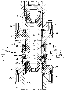
1000581 In FIG. 1, riser spool or housing 12 is positioned with marine riser
sections (4, 10).
Marine riser sections (4, 10) are part of a marine riser, such as disclosed
above in the
Background of the Invention. Housing 12 is illustrated bolted with bolts (24,
26) to
respective marine riser sections (4, 10). Other attachment means are
contemplated. An RCD
2 with two passive stripper seals (6, 8) is landed in and latched to housing
12 using first
latching member 14 and second latching member 18, both of which may be
actuated by
hydraulic pistons, such as described in the '837 patent (see Figures 2 and 3
of '837 patent).
Active packer seal 22 in housing 12, shown in its noninflated and unsealed
position, may be
699012 8/SP11/65501/0064/122109
= CA 02690289 2010-01-14
hydraulically expandable to a sealed position to sealingly engage the outside
diameter of
RCD 2.
1000591 Remote Operated Vehicle (ROV) subsea control panel 28 may be
positioned with
housing 12 between protective flanges (30, 32) for operation of hydraulic
latching members
(14, 18) and active packer seal 22. An ROV 3 containing hydraulic fluid may be
sent below
sea level to connect with the ROV panel 28 to control operations the housing
12 components.
The ROV 3 may be controlled remotely from the surface. In particular, by
supplying
hydraulic fluid to different components using shutter valves and other
mechanical devices,
latching members (14, 18) and active seal 22 may be operated. Alternatively,
or in addition
for redundancy, one or more hydraulic lines, such as line 5, may be run from
the surface to
supply hydraulic fluid for remote operation of the housing 12 latching members
(14, 18) and
active seal 22. Alternatively, or in addition for further redundancy and
safety, an
accumulator 7 for storing hydraulic fluid may be activated remotely to operate
the housing 12
components or store fluids under pressure. It is contemplated that all three
means for
hydraulic fluid would be provided. It is also contemplated that a similar ROV
panel, ROV,
hydraulic lines, and/or accumulator may be used with all embodiments of the
invention,
although not shown for clarity in all the below Figures.
21
699012 8/SP11/65501/0064/122109
1(177 Addc_l -rnh=annlnn
CA 02690289 2010-01-14
1000601 The RCD 2 outside diameter is smaller than the housing 12 inside
diameter or
straight thru bore. First retainer member 16 and second retainer member 20 are
shown in
FIG. 1 after having been moved from their respective first or unlatched
positions to their
respective second or latched positions. RCD 2 may have a change in outside
diameter that
occurs at first retainer member 16. As shown in FIG. 1, the upper outside
diameter 9 of RCD
2 may be greater than the lower outside diameter 31 of RCD 2. Other RCD
outside surface
configurations are contemplated, including the RCD not having a change in
outside diameter.
1000611 As shown in FIGS. 1 and 1A, the RCD 2 upper outside diameter 9 above
the
second retainer member 20 and between the first 16 and second 20 retainer
members may
have a plurality of vertical grooves 23. As shown in FIG. 1A, second retainer
member 20
may be a plurality of dogs. First retainer member 16 may also be a plurality
of dogs like
second retainer member 20. Retainer members (16, 20) may be segmented locking
dogs.
Retainer members (16, 20) may each be a split ring or C-shaped member, or they
may each
be a plurality of segments of split ring or C-shaped members. Retainer members
(16, 20)
may be biased radially outwardly. Retainer members (16, 20) may each be
mechanical
interlocking members, such as tongue and groove type or T-slide type, for
positive retraction.
Other retainer member configurations are contemplated.
22
699012 8/SP1-1/65501/0064/122109
7(177444-1-mhanmann
. CA 02690289 2010-01-14
1000621 The vertical grooves 23 along the outside surface of RCD 2 allow for
fluid
passageways 25 when dogs 20 are in the latched position as shown in FIG. 1A.
The vertical
grooves 23 allow for the movement of fluids around the RCD 2 when the RCD 2 is
moved in
the riser. The vertical grooves 23 are provided to prevent the compression or
surging of
fluids in the riser below the RCD 2 when RCD 2 is lowered or landed in the
riser and
swabbing or a vacuum effect when the RCD 2 is raised or retrieved from the
riser.
1000631 Returning to FIG. 1, first retainer member 16 blocks the downward
movement of
the RCD 2 during landing by contacting RCD blocking shoulder 11, resulting
from the
change between upper RCD outside diameter 9 and lower RCD outside diameter 31.
Second
retainer member 20 has engaged the RCD 2 in a horizontal radial receiving
groove 33 around
the upper outside diameter 9 of RCD 2 to squeeze or compress the RCD 2 between
retainers
(16, 20) to resist rotation. In their second or latched positions, retainer
members (16, 20) also
may squeeze or compress RCD 2 radially inwardly. It is contemplated that
retainer members
(16, 20) may be alternatively moved to their latched positions radially
inwardly and axially
upwardly to squeeze or compress the RCD 2 using retainers (16, 20) to resist
rotation. As
can now be understood, the RCD may be squeezed or compressed axially upwardly
and
downwardly and radially inwardly. In their first or unlatched positions,
retainer members
23
699012 8/SPH/65501/0064/122109
`2A77 A A AG
CA 02690289 2010-01-14
(16, 20) allow clearance between the RCD 2 and housing 12. In their second or
latched
positions, retainer members (16, 20) block and latchingly engage the RCD 2,
respectively, to
resist vertical movement and rotation. The embodiment shown in FIGS. 1 and IA
for the
outside surface of the RCD 2 may be used for all embodiments shown in all the
Figures.
[00064] While it is contemplated that housing 12 may have a 10,000 psi body
pressure
rating, other pressure ratings are contemplated. Also, while it is
contemplated that the
opposed housing flanges (30, 32) may have a 39 inch (99.1 cm) outside
diameter, other sizes
are contemplated. RCD 2 may be latchingly attached with a 21.250 inch (54 cm)
tluu bore
34 of marine riser sections (4, 10) with a 19.25 (48.9 cm) inch inside bore
12A of housing 12.
Other sizes are contemplated. It is also contemplated that housing 12 may be
positioned
above or be integral with a marine diverter, such as a 59 inch (149.9 cm)
inside diameter
marine diverter. Other sizes are contemplated. The diverter will allow fluid
moving down
the drill pipe and up the annulus to flow out the diverter opening below the
lower stripper
seal 8 and the same active seal 22. Although active seal 22 is shown below the
bearing
assembly of the RCD 2 and below latching members (14, 18), it is contemplated
that active
seal 22 may be positioned above the RCD bearing assembly and latching members
(14, 18).
It is also contemplated that there may be active seals both above and below
the RCD bearing
24
699012 8/SPH/65501/0064/122109
CA 02690289 2010-01-14 -
=
assembly and latching members (14, 18). All types of seals, active or passive,
as are known
in the art are contemplated. While the active seal 22 is illustrated
positioned with the housing
12, it is contemplated that the seal, active or passive, could instead be
positioned with the
outer surface of the RCD 2.
1000651 In the preferred method, to establish a landing for RCD 2, which may
be an 18.00
inch (45.7 cm) outer diameter RCD, the first retainer member 16 is remotely
activated to the
latched or loading position. The RCD 2 is then moved into the housing 12 until
the RCD 2
lands with the RCD blocking shoulder 11 contacting the first retainer member
16. The
second retainer member 20 is then remotely activated with hydraulic fluid
supplied as
discussed above to the latched position to engage the RCD receiving groove 33,
thereby
creating a clamping force on the RCD 2 outer surface to, among other benefits,
resist torque
or rotation. In particular, the top chamfer on first retainer member 16 is
engaged with the
RCD shoulder 11. When the bottom chamfer on the second retainer member 20
moves into
receiving groove 33 on the RCD 2 outer surface, the bottom chamfer "squeezes"
the RCD
between the two retainer members (16, 20) to apply a squeezing force on the
RCD 2 to resist
torque or rotation. The active seal 22 may then be expanded with hydraulic
fluid supplied as
699012 8/SPH/65501/0064/122109
CA 02690289 2010-01-14 _
discussed above to seal against the RCD 2 lower outer surface to seal the gap
or annulus
between the RCD 2 and the housing 12.
[00066] The operations of the housing 12 may be controlled remotely through
the ROV
fluid supplied to the control panel 28, with hydraulic line 5 and/or
accumulator 7. Other
methods are contemplated, including activating the second retainer member 20
simultaneously with the active seal 22. Although a bypass channel or line,
such as an internal
bypass channel 68 shown in FIG. 2 and an external bypass line 186 shown in
FIG. 4A, is not
shown in FIG. 1, it is contemplated that a similar external bypass line or
internal bypass
channel with a valve may be used in FIG. 1 or in any other embodiment. The
operation of a
bypass line with a valve is discussed in detail below with FIG. 2.
[00067] Turning to FIG. 2, an RCD 40 with three passive stripper seals (41,
46, 48) is
positioned with riser spool or housing 72 with first retainer member 56 and
second retainer
member 60, both of which are activated by respective hydraulic pistons in
respective latching
members (54, 58). First retainer member 56 blocks movement of the RCD 40 when
blocking
shoulder 43 engages retainer member 56 and second retainer member 60 is
positioned with
RCD receiving formation or groove 45. The operations of the housing 72
components may
be controlled remotely using ROV 61 connected with ROV control panel 62
positioned
26
699012 8/SPH/65501/0064/122109
CA 02690289 2010-01-14
between flanges (74, 76) and further protected by shielding member 64.
Alternatively, or in
addition, as discussed above, housing 74 components may be operated by
hydraulic lines
and/or accumulators. RCD stripper seal 41 is inverted from the other stripper
seals (46, 48)
to, among other reasons, resist "suck down" of drilling fluids during a total
or partial loss
circulation. Such a loss circulation could result in the collapse of the riser
if no fluids were in
the riser to counteract the outside forces on the riser. For RCD 40 in FIG. 2,
and for similar
RCD stripper seal embodiments in the other Figures, it is contemplated that
the two opposing
stripper seals, such as stripper seals (41, 46), may be one integral or
continuous seal rather
than two separate seals.
[00068] The RCD 40 outside diameter is smaller than the housing 72 inside
diameter,
which may be 19.25 inches (48.9 cm). Other sizes are contemplated. While the
riser housing
72 may have a 10,000 psi body pressure rating, other pressure ratings are
contemplated.
Retainer members (56, 60) may be a plurality of dogs or a C-shaped member,
although other
types of members are contemplated. Active seal 66, shown in an unexpanded or
unsealed
position, may be expanded to sealingly engage RCD 40. Alternatively, or in
addition, an
active seal may be positioned above the RCD bearing assembly and latching
members (54,
58). Housing 74 is illustrated bolted with bolts (50, 52) to marine riser
sections (42, 44). As
27
699012 8/SP1-1/65501 /0064/122109
CA 02690289 2010-01-14
discussed above, other attachment means are contemplated. While it is
contemplated that the
opposed housing flanges (74, 76) may have a 45 inch (114.3 cm) outside
diameter, other sizes
are contemplated. As can now be understood, the RCD 40 may be latchingly
attached with
the thru bore of housing 72. It is also contemplated that housing 74 may be
positioned with a
59 inch (149.9 cm) inside diameter marine diverter.
[000691 The system shown in FIG. 2 is generally similar to the system shown in
FIG. 1,
except for internal bypass channel 68, which, as stated above, may be used
with any of the
embodiments. Valve 78, such as a gate valve, may be positioned in bypass
channel 68. Two
end plugs 70 may be used after internal bypass channel 68 is manufactured,
such as shown in
FIG. 2, to seal communication with atmospheric pressure outside the wellbore.
Bypass
channel 68 with gate valve 78 acts as a check valve in well kick or blowout
conditions. Gate
valve 78 may be operated remotely. For example, if hazardous weather
conditions are
forecasted, the valve 78 could be closed with the riser sealable controlled
and the offshore rig
moved to a safer location. Also, if the riser is raised with the RCD in place,
valve 78 could
be opened to allow fluid to bypass the RCD 40 and out the riser below the
housing 72 and
RCD 40. In such conditions, fluid may be allowed to flow through bypass
channel 68,
around RCD 40, via bypass channel first end 80 and bypass channel second end
82, thereby
28
699012 VSP11/65501/0064/122109
,,,õ .
CA 02690289 2010-01-14
bypassing the RCD 40 sealed with housing 72. Alternatively to internal bypass
channel 68, it
is contemplated that an external bypass line, such as bypass line 186 in FIG.
4A, may be
used with FIG. 2 and any other embodiments.
[00070] In FIG. 3A, riser spool or housing 98 is illustrated connected with
threaded shafts
and nuts 116 to marine riser section 100. An RCD 90 having a seal assembly 92
is positioned
with an RCD running tool 94 with housing 98. Seal assembly latching formations
118 may
be positioned in the J-hook receiving grooves 96 in RCD running tool 94 so
that the running
tool 94 and RCD 90 are moved together on the drill string through the marine
riser and
housing 98. Other attachment means are contemplated as are known in the art. A
running
tool, such as running tool 94, may be used to position an RCD with any riser
spool or housing
embodiments. RCD 90 is landed with housing 98 with first retainer member 106
and
squeezed with second retainer member 110, both of which are remotely actuated
by
respective hydraulic pistons in respective latching members (104, 108). First
retainer
member 106 blocks RCD shoulder 105 and second retainer member 110 is
positioned with
RCD second receiving formation or groove 107.
[00071] ROV control panel 114 may be positioned with housing 98 between upper
and
lower shielding protrusions 112 (only lower protrusion shown) to protect the
panel 114.
29
699012 8/SPH/65501/0064/122109
- CA 02690289 2010-01-14
Other shielding means are contemplated. While it is contemplated that the
opposed housing
flanges 120 (only lower flange shown) of housing 98 may have a 45 inch (114.3
cm) outside
diameter, other sizes are contemplated. The RCD 90 outside diameter is smaller
than the
housing 98 inside diameter. Retainer members (106, 110) may be a plurality of
dogs or a C-
shaped member. Active seal 102, shown in an expanded or sealed position,
sealingly engages
RCD 102. After the RCD 90 is sealed as shown in FIG. 3A, the running tool 94
may be
disengaged from the RCD seal assembly 92 and continue moving with the drill
string down
the riser for drilling operations. Alternatively, or in addition, an active or
passive seal may be
positioned on RCD 90 instead of on housing 98, and/or may be positioned both
above and
below RCD bearing assembly or latching members (104, 108). Alternatively to
the
embodiment shown in FIG. 3A, a seal assembly, such as seal assembly 92, may be
positioned
above the RCD bearing assembly or latching members (104, 108) to engage an RCD
running
tool. The alternative seal assembly may be used to either house a seal, such
as seal 102, or be
used as the portion of the RCD to be sealed by a seal in a housing, similar to
the embodiment
shown in FIG. 3A.
1000721 Generally, lines and cables extend radially outwardly from the riser,
as shown in
FIG. 1 of the '171 patent, and male and female members of the lines and cables
can be
699012 8/SPH/65501/0064/122109
1C177AA,M I mknet=-===-=r%.,
CA 02690289 2010-01-14
plugged together as the riser sections are joined together. Turning to FIG.
3B, an exemplary
rerouting or placement of these lines and cables is shown external to housing
98 within the
design criteria inside diameter 130 as the lines and cables traverse across
the housing 98.
Exemplary lines and cables may include 1.875 inch OD multiplex cables 134,
2.375x 2.000
rigid conduit lines 136, a 5.563 x 4.5 mud boost line 138, a 7 x 4.5 kill line
140, a 7 x 4.5
choke line 142, a 7.5 x 6 mud return line 144, and a 7.5 x 6 sea water fluid
power line 146.
Other sizes, lines and cables and configurations are contemplated. It is also
contemplated
that an ROV or accumulator(s) may be used to replace some of the lines and/or
conduits.
1000731 It is contemplated that a marine riser segment would stab the male or
pin end of its
riser tubular segment lines and cables with the female or box end of a lower
riser tubular
segment lines and cables. The lines and cables, such as shown in FIG. 3B, may
also be
stabbed or plugged with riser tubular segment lines and cables extending
radially outward so
that they may be plugged together when connecting the riser segments. In other
words, the
lines and/or cables shown in FIG. 3B are rerouted along the vertical elevation
profile exterior
to housing 98 to avoid housing protrusions, such as panel 114 and protrusion
112, but the
lines and cables are aligned racially outward to allow them to be connected
with their
respective lines and cables from the adjoining riser segments. Although
section 3B-3B is
31
699012 8/SPH/65501/0064/122109
1(177/144-1-mhanmann
CA 02690289 2010-01-14 =
only shown with FIG. 3A, similar exemplary placement of the ROV panel, lines,
and cables
as shown in FIG. 3B may be used with any of the embodiments.
[00074] An external bypass line 186 with gate valve 188 is shown and discussed
below
with FIG. 4A. Although FIG. 3A does not show a bypass line and gate valve, it
is
contemplated that the embodiment in FIG. 3A may have a bypass line and gate
valve. FIG.
3B shows an exemplary placement of a gate valve 141 with actuator 143 if used
with FIG.
3A. A similar placement may be used for the embodiment in FIG. 4A and other
embodiments.
[00075] In FIGS. 4A-4B, riser spools or housings (152A, 152B) are bolted
between marine
riser sections (154, 158) with respective bolts (156, 160). Housing 152A is
bolted with
housing 152B using bolts 157. A protection member 161 may be positioned with
one or
more of the bolts 157 (e.g., three openings in the protection member to
receive three bolts) to
protect an ROV panel, which is not shown. An RCD 150 with three passive
stripper seals
(162, 164, 168) is positioned with riser spools or housings (152A, 152B) with
first retainer
member 172, second retainer member 176, and third retainer member or seal
assembly
retainer 182 all of which are activated by respective hydraulic pistons in
their respective
latching members (170, 174, 180). Retainer members (172, 176, 182) in housing
152B as
32
699012 8/S11-1/65501/0064/122109
30774445-1-mhaamann
CA 02690289 2010-01-14
=
shown in FIG. 4B have been moved from their respective first or unlatched
positions to their
respective second or latched positions. First retainer member 172 blocks RCD
shoulder 173
and second retainer member 176 is positioned with RCD receiving formation or
groove 175.
The operations of the housing 152B may be controlled remotely using in any
combination an
ROV connected with an ROV containing hydraulic fluid and control panel,
hydraulic lines,
and/or accumulators, all of which have been previously described but not shown
for clarity of
the Figure.
[00076] The RCD seal assembly, generally indicated at 178, for RCD 150 and the
RCD
running tool 184 are similar to the seal assembly and running tool shown in
FIGS. 10A-10E
and are described in detail below with those Figures. RCD stripper seal 162 is
inverted from
the other stripper seals (164, 168). Although RCD seal assembly 178 is shown
below the
RCD bearing assembly and below the first and second latching members (170,
174), a seal
assembly may alternatively be positioned above the RCD bearing assembly and
the first and
second latching members (170, 174) for all embodiments.
1000771 External bypass line 186 with valve 188 may be attached with housing
152 with
bolts (192, 196). Other attachment means are contemplated. A similar bypass
line and valve
may be positioned with any embodiment. Unlike bypass channel 68 in FIG. 2,
bypass line
33
699012 8/SP11/65501/0064/122109
11177 AA Ac_l
CA 02690289 2010-01-14
186 in FIGS. 4A-4B is external to and releasable from the housings (152A,
152B). Bypass
line 186 with gate valve 188 acts as a check valve in well kick or blowout
conditions. Gate
valve 188 may be operated remotely. Also, if hazardous weather conditions are
forecasted,
the valve 188 could be closed with the riser sealable controlled and the
offshore rig moved to
a safer location.
1000781 Also, when the riser is raised with the RCD in place, valve 188 could
be opened to
allow fluid to bypass the RCD 150 and out the riser below the housing 152B and
RCD 150.
In such conditions when seal assembly extrudable seal 198 is in a sealing
position (as
described below in detail with FIGS. 10A-10E), fluid may be allowed to flow
through bypass
line 186, around RCD 150, via bypass line first end 190 and bypass line second
end 194,
thereby bypassing RCD 150 sealed with housing 152B. Alternatively to external
bypass line
186, it is contemplated that an internal bypass channel, such as bypass
channel 68 in FIG. 2,
may be used with FIGS. 4A-4B and any other embodiment.
[00079] Turning to FIGS. 5A-5B, riser spool or housing 202 is illustrated
bolted to marine
riser sections (204, 208) with respective bolts (206, 210). An RCD 200 having
three passive
seals (240, 242, 244) and a seal assembly 212 is positioned with an RCD
running tool 216
used for positioning the RCD 200 with housing 202. Seal assembly latching
formations 214
34
699012 8/SP11/65501/0064/122109
CA 02690289 2010-01-14
may be positioned in the J-hook receiving grooves 218 in RCD running tool 216
and the
running tool 216 and RCD 200 moved together on the drill string through the
marine riser.
RCD 200 is landed with housing 202 with first retainer member 222 and latched
with second
retainer member 226, both of which are remotely actuated by respective
hydraulic pistons in
respective latching members (220, 224). First retainer member 222 blocks RCD
shoulder
223 and second retainer member 226 is positioned with RCD receiving formation
or groove
225.
1000801 Upper 202A, intermediate 202B, and lower 202C active packer seals may
be used
to seal the annulus between the housing 202 and RCD 200. Upper seal 202A and
lower
active seal 202C may be sealed together to protect latching members (220,
224).
Intermediate active seal 202B may provide further division or redundancy for
seal 202C. It is
also contemplated that lower active seal 202C may be sealed first to seal off
the pressure in
the riser below the lower seal 202C. Upper active seal 202A may then be sealed
at a pressure
to act as a wiper to resist debris and trash from contacting latching members
(220, 224).
Other methods are contemplated. Sensors (219, 229, 237) may be positioned with
housing
202 between the seals (202A, 202B, 202C) to detect wellbore parameters, such
as pressure,
temperature, and/or flow. Such measurements may be useful in determining the
effectiveness
699012 8/SM/65501/0064/122109
11177 A A
CA 02690289 2010-01-14
of the seals (202A, 202B, 202C), and may indicate if a seal (202A, 202B, 202C)
is not
sealing properly or has been damaged or failed.
1000811 It is also contemplated that other sensors may be used to determine
the relative
difference in rotational speed (RPM) between any of the RCD passive seals
(240, 242, 244),
for example, seals 240 and 242. For the embodiment shown in FIGS. 5A-5B, as
well as all
other embodiments, a data information gathering system, such as DIGS, provided
by
Weatherford may be used with a PLC to monitor and/or reduce relative slippage
of the
sealing elements (240, 242, 244) with the drill string. It is contemplated
that real time
revolutions per minute (RPM) of the sealing elements (240, 242, 244) may be
measured. If
one of the sealing elements (240, 242, 244) is on an independent inner member
and is turning
at a different rate than another sealing element (240, 242, 244), then it may
indicate slippage
of one of the sealing elements with tubular. Also, the rotation rate of the
sealing elements
can be compared to the drill string measured at the top drive (not shown) or
at the rotary table
in the drilling floor.
1000821 The information from all sensors, including sensors (219, 229, 237),
may be
transmitted to the surface for processing with a CPU through an electrical
line or cable
positioned with hydraulic line 5 shown in FIG. 1. An ROV may also be used to
access the
36
699012 8/SP11/65501/0064/122109
CA 02690289 2010-01-14
information at ROV panel 228 for processing either at the surface or by the
ROV. Other
methods are contemplated, including remote accessing of the information. After
the RCD
200 is latched and sealed as shown in FIG. 5B, the running tool 216 may be
disengaged from
the RCD 200 and continue moving with the drill string down the riser for
drilling operations.
1000831 ROV control panel 228 may be positioned with housing 200 between two
shielding
protrusions 230 to protect the panel 228. The RCD 200 outside diameter is
smaller than the
housing 202 inside diameter. Retainer members (222, 226) may be a plurality of
dogs or a C-
shaped member. External bypass line 232 with valve 238 may be attached with
housing 202
with bolts (234, 236). Other attachment means are contemplated. Bypass line
232 with gate
valve 238 acts as a check valve in well kick or blowout conditions. Valve 238
may be
operated remotely.
1000841 Turning to FIG. 6A, RCD 250 having a seal assembly, generally
designated at 286,
is shown latched in riser spool or housing 252 with first retainer member 256,
second retainer
member 260, and third retainer member or seal assembly retainer 264 of
respective latching
members (254, 258, 262) in their respective second or latched/landed
positions. First retainer
member 256 blocks RCD shoulder 257 and second retainer member 260 is
positioned with
RCD receiving formation or groove 259. An external bypass line 272 is
positioned with
37
699012 8/SPH/65501/0064/122109
-CA 02690289 2010-01-14
housing 252. An ROV panel 266 is disposed with housing 252 between two
shielding
protrusions 268. Seal assembly 286 comprises RCD extension or extending member
278,
tool member 274, retainer receiving member 288, seal assembly seal 276, upper
or first shear
pins 282, lower or second shear pins 280, and ratchet shear ring or ratchet
shear 284.
Although two upper 282 and two lower 280 shear pins are shown for this and
other
embodiments, it is contemplated that there may be only one upper 282 and one
lower 280
shear pin or that there may be a plurality of upper 282 and lower 280 shear
pins of different
sizes, metallurgy and shear rating. Other mechanical shearing devices as are
known in the art
are also contemplated.
[00085] Seal assembly seal 276 may be bonded with tool member blocking
shoulder 290
and retainer receiving member 288, such as by epoxy. A lip retainer formation
in either or
both the tool member 274 and retainer receiving member 288 that fits with a
corresponding
formation(s) in seal 276 is contemplated. This retainer formation, similar to
formation 320
shown and/or described with FIG. 7A, allows seal 276 to be connected with the
tool member
274 and/or retainer receiving member 288. A combination of bonding and
mechanical
attachment as described above may be used. Other attachment methods are
contemplated.
38
699012 8/SP1-1/65501/0064 122109
CA 02690289 2010-01-14
The attachment means shown and discussed for use with extrudable seal 276 may
be used
with any extrudable seal shown in any embodiment.
[00086] Extrudable seal 276 in FIG. 6A, as well as all similar extrudable
seals shown in all
RCD sealing assemblies in all embodiments, may be made from one integral or
monolithic
piece of material, or alternatively, it may be made from two or more segments
of different
materials that are formed together with structural supports, such as wire mesh
or metal
supports. The different segments of material may have different properties.
For example, if
the seal 276 were made in three segments of elastomers, such as an upper,
intermediate, and
lower segment when viewed in elevational cross section, the upper and lower
segments may
have certain properties to enhance their ability to sandwich or compress a
more extrudable
intermediate segment. The intermediate segment may be formed differently or
have different
properties that allow it to extrude laterally when compressed to better seal
with the riser
housing. Other combinations and materials are contemplated.
[00087] Seal assembly 286 is positioned with RCD running tool 270 with lower
shear pins
280 and running tool shoulder 271. After the running tool is made up in the
drill string, the
running tool 270 and RCD 250 are moved together from the surface down through
the marine
riser to housing 252 in the landing position shown in FIG. 6A. In one method,
it is
39
699012 8/SPH/65501/0064/122109
= CA 02690289 2010-01-14
contemplated that before the RCD 250 is lowered into the housing 252, first
retainer member
256 would be in the landing position, and second 260 and third 264 retainer
members would
be in their unlatched positions. RCD shoulder 257 would contact first retainer
member 256,
which would block downward movement. Second retainer member 260 would then be
moved to its latched position engaging RCD receiving formation 259, which, as
discussed
above, would squeeze the RCD between the first 256 and second 260 retaining
members to
resist rotation. Third retaining member would then be moved to its latched
position with
retainer receiving member 288, as shown in FIG. 6A. After landing, the seal
assembly seal
276 may be extruded as shown in FIG. 6B. It should be understood that the
downward
movement of the running tool and RCD may be accomplished using the weight of
the drill
string. For all embodiments of the invention shown in all the Figures, it is
contemplated that
a latch position indicator system, such as one of the embodiments proposed in
the '837 patent
or the '724 publication, may be used to determine whether the latching
members, such as
latching members (254, 258, 262) of FIG. 6A, are in their latched or unlatched
positions. It is
contemplated that a comparator may compare hydraulic fluid values or
parameters to
determine the positions of the latches. It is also contemplated that an
electrical switch
699012 8/S PH/65501/0064/122109
CA 02690289 2010-01-14
system, a mechanical valve system and/or a proximity sensor system may be
positioned with
a retainer member. Other methods are contemplated.
1000881 It is contemplated that seal assembly 286 may be detachable from RCD
250, such
as at locations (277A, 277B). Other attachment locations are contemplated.
Seal assembly
286 may be threadingly attached with RCD 250 at locations (277A, 277B). Other
types of
connections are contemplated. The releasable seal assembly 286 may be removed
for repair,
and/or for replacement with a different seal assembly. It is contemplated that
the replacement
seal assembly would accommodate the same vertical distance between the first
retainer
member 256, the second retainer member 260 and the third retainer member 264.
All seal
assemblies in all the other embodiments in the Figures may similarly be
detached from their
RCD.
1000891 FIG. 6B shows the setting position used to set or extrude seal
assembly seal 276 to
seal with housing 252. To set the extrudable seal 276, the running tool 270 is
moved
downward from the landing position shown in FIG. 6A. This downward motion
shears the
upper shear pin 282 but not the lower shear pin 280. This downward movement
also ratchets
the ratchet shear ring 284 upwardly. As can now be understood, lower shear pin
280 has a
higher shear and ratchet force than upper shear pin 282 and ratchet shear ring
284,
41
699012 8/SPH '65501/0064/122 109
CA 02690289 2010-01-14
respectively, relative to retainer receiving member 288 and then maintains the
relative
position. Therefore, ratchet shear ring 284 allows the downward movement of
the tool
member 274. The running tool 270 pulls the tool member 274 downward. It is
contemplated
that the force needed to fully extrude seal 276 is less than the shear
strength of upper shear
pin 282.
[00090] When upper shear pin 282 is sheared, there is sufficient force to
fully extrude seal
276. Tool member 274 will move downward after upper shear pin 282 is sheared.
Tool
member blocking shoulder 292 prevents further downward movement of the tool
member
274 when shoulder 292 contacts the upward facing blocking shoulder 294 of RCD
extending
member 278. However, it is contemplated that the seal 276 will be fully
extruded before tool
member 274 blocking shoulder 292 contacts upward facing shoulder 294. Ratchet
shear ring
284 prevents tool member 274 from moving back upwards after tool member 274
moves
downwards.
1000911 Shoulder 290 of tool member 274 compresses and extrudes seal 276
against
retainer receiving member 288, which is held fixed by third retainer member
264. During
setting, ratchet shear ring 284 allows tool member 274 to ratchet downward
with minimal
resistance and without shearing the ring 284. After the seal 276 is set as
shown in FIG. 6B,
42
699012 8/SP11/65501/0064 '122109
CA 02690289 2010-01-14.
running tool 270 may continue downward through the riser for drilling
operations by shearing
the lower shear pin 280. Ratchet shear ring 284 maintains tool member 274 from
moving
upward after the lower shear pin 280 is sheared, thereby keeping seal assembly
seal 276
extruded as shown in FIG. 6B during drilling operations. As can now be
understood, for the
embodiment shown in FIGS. 6A-6C, the weight of the drill string moves the
running tool 270
downward for setting the seal assembly seal 276.
[00092] As shown in the FIG. 6B view, it is contemplated that shoulder 290 of
tool member
274 may be sloped with a positive slope to enhance the extrusion and sealing
of seal 276 with
housing 252 in the sealed position. It is also contemplated that the upper
edge of retainer
receiving member 288 that may be bonded with seal 276 may have a negative
slope to
enhance the extrusion and sealing of seal 276 in the sealed position with
housing 252. The
above described sloping of members adjacent to the extrudable seal may be used
with all
embodiments having an extrudable seal. For FIG. 6A and other embodiments with
extrudable seals, it is contemplated that if the distance between the outer
facing surface of the
unextruded seal 276 as it is shown in FIG. 6A, and the riser housing 252 inner
bore surface
where the extruded seal 276 makes contact when extruded is .75 inch (1.91 cm)
to 1 inch
(2.54 cm), then 2000 to 3000 of sealing force could be provided. Other
distances or gaps and
43
52/CPLI/GS111 /Arit.A/1/5 Inc)
CA 02690289 2010-01-14
=
sealing forces are contemplated. It should be understood that the greater the
distance or gap,
the lower the sealing force of the seal 276. It should also be understood that
the material
composition of the extrudable seal will also affect its sealing force.
1000931 FIG. 6C shows the housing 252 in the fully released position for
removal or
retrieval of the RCD 250 from the housing 252. After drilling operations are
completed, the
running tool 270 may be moved upward through the riser toward the housing 252.
When
running tool shoulder 271 makes contact with tool member 274, as shown in FIG.
6C, first,
second and third retainer members (256, 260, 264) should be in their latched
positions, as
shown in FIG. 6C. Running tool shoulder 271 then pushes tool member 274
upward,
shearing the teeth of ratchet shear ring 284. As can now be understood,
ratchet shear ring
284 allows ratcheting in one direction, but shears when moved in the opposite
direction upon
application of a sufficient force. Tool member 274 moves upward until upwardly
facing
blocking shoulder 296 of tool member 274 contacts downwardly facing blocking
shoulder
298 of extending member 278. The pin openings used to hold the upper 282 and
lower 280
shear pins should be at substantially the same elevation before the pins were
sheared. FIG.
6C shows the sheared upper 282 and lower 280 shear pins being aligned. Again,
the pins
44
699012 8'SM/65501/0064/122109
CA 02690289 2010-01-14 -
could be continuous in the pin opening or equidistantly spaced as desired and
depending on
the pin being used.
1000941 When tool member 274 moves upward, tool member blocking shoulder 290
moves
upward, pulling seal assembly seal 290 relative to fixed retainer receiving
member 288
retained by the third retainer member 264 in the latched position. The seal
290 is preferably
stretched to substantially its initial shape, as shown in FIG. 6C. The
retainer members (256,
260, 264) may then be moved to their first or unlatched positions as shown in
FIG. 6C, and
the RCD 250 and running tool 270 removed together upward from the housing 252.
1000951 Turning to FIG. 7A, RCD 300 and its seal assembly, generally
designated 340, are
shown latched in riser spool or housing 302 with first retainer member 304,
second retainer
member 308, and third retainer member or seal assembly retainer 324 of
respective latching
members (306, 310, 322) in their respective second or latched/landed
positions. First retainer
member 304 blocks RCD shoulder 342 and second retainer member 308 is
positioned with
RCD second receiving formation 344. An external bypass line 346 is positioned
with
housing 302. An ROV panel 348 is disposed with housing 302 between a shielding
protrusion 350 and Flange 302A. Seal assembly 340 comprises RCD extending
member 312,
RCD tool member 314, tool member 330, retainer receiving member 326, seal
assembly seal
699012 8, SPH/6550 I /0064/122 109
CA 02690289 2010-01-14
318, upper shear pins 316, intermediate shear pins 332, lower shear pins 334,
ratchet or lock
ring 328, inner split C-ring 352, and outer split C-ring 354. Inner C-ring 352
has shoulder
358. Tool member 314 has downwardly facing blocking shoulders (368, 360). Tool
member
330 has upwardly facing blocking shoulders 362 and downwardly facing blocking
shoulder
364. Retainer receiving member 326 has downwardly facing blocking shoulder
366.
Extending member 312 has downwardly facing blocking shoulder 370.
1000961 Although two upper 316, two lower 334 and two intermediate 332 shear
pins are
shown, it is contemplated that there may be only one upper 316, one lower 334
and one
intermediate 332 shear pin or, as discussed above, that there may be a
plurality of upper 316,
lower 334 and intermediate 332 shear pins. Other mechanical shearing devices
as are known
in the art are also contemplated. Seal assembly seal 318 may be bonded with
RCD tool
member 314 and retainer receiving member 326, such as by epoxy. A lip retainer
formation
320 in RCD tool member 314 fits with a corresponding formation in seal 318 to
allow seal
318 to be pulled by RCD tool member 314. Although not shown, a similar lip
formation may
be used to connect the seal 318 with retainer receiving member 326. A
combination of
bonding and mechanical attachment as described above may be used.
46
699012 S/SPH/65501/0064/122109
. CA 02690289 2010-01-14
[00097] Seal assembly 340 is positioned with RCD running tool 336 with lower
shear pins
334, running tool shoulder 356, and concentric C-rings (352, 354). The running
tool 336 and
RCD 300 are moved together from the surface through the marine riser down into
housing
302 in the landing position shown in FIG. 7A. In one method, it is
contemplated that before
the RCD 300 is lowered into the housing 302, first retainer member 304 would
be in the
landed position, and second 308 and third 324 retainer members would be in
their unlatched
positions. RCD shoulder 342 would be blocked by first retainer member 304 to
block the
downward movement of the RCD 300. Second retainer member 308 would then be
moved to
its latched position engaging RCD receiving formation 344, which would squeeze
the RCD
between the first 304 and second 308 retaining members to resist rotation.
Third retaining
member 324 would then be moved to its latched position with retainer receiving
member 326
as shown in FIGS. 7A-7C. After landing is completed, the seal assembly seal
318 may be set
or extruded.
1000981 FIG. 7B shows the setting position used to set or extrude seal
assembly seal 318
with housing 302. To set the extrudable seal 318, the running tool 336 is
moved downward
from the landing position shown in FIG. 7A so that the shoulder 365 of running
tool 336
pushes the inner C-ring 352 downward. Inner C-ring 352 contacts blocking
shoulder 362 of
47
699012 8/SPH/65501/0064/122109
CA 02690289 2010-01-14
tool member 330, and pushes the tool member 330 down until the blocking
shoulder 364 of
the tool member 330 contacts the blocking shoulder 366 of retainer receiving
member 326, as
shown in FIG. 7B. Outer C-ring 354 then moves inward into groove 358 of inner
C-ring 352
as shown in FIG. 7B. The downward motion of the running tool 336 first shears
the lower
shear pins 334, and after inner C-ring 352 urges tool member 330 downward, the
upper shear
pins 316 are sheared, as shown in FIG. 7B. The intermediate shear pins 332 are
not sheared.
As can now be understood, the intermediate shear pins 332 have a higher shear
strength than
the upper shear pins 316 and lower shear pins 334. The intermediate shear pin
332 pulls
RCD tool member 314 downward until downwardly facing blocking shoulder 368 of
RCD
tool member 314 contacts upwardly facing blocking shoulder 370 of RCD
extending member
312. The ratchet or lock ring 328 allows the downward ratcheting of tool
member 330
relative to retainer receiving member 326. Like ratchet shear ring 284 of
FIGS. 6A-6C,
ratchet or lock ring 328 of FIGS. 7A-7C allows ratcheting members. However,
unlike ratchet
shear ring 284 of FIGS. 6A-6C, ratchet or lock ring 328 of FIGS. 7A-7C is not
designed to
shear when tool member 330 moves upwards, but rather ratchet or lock ring 328
resists the
upward movement of the adjacent member to maintain the relative positions.
48
699012 81SPH/65501/0064/122109
CA 02690289 2010-01-14
1000991 Shoulder 360 of RCD tool member 314 compresses and extrudes seal 318
against
retainer receiving member 326, whicli is fixed by third retainer member 324.
After the seal
318 is set as shown in FIG. 7B, running tool 336 may continue downward through
the riser
for drilling operations. Ratchet or lock ring 328 and intermediate shear pin
332 prevent tool
member 330 and RCD tool member 314 from moving upwards, thereby maintaining
seal
assembly seal 318 extruded as shown in FIG. 7B during drilling operations. As
can now be
understood, for the embodiment shown in FIGS. 7A-7C, the running tool 336 is
moved
downward for setting the seal assembly seal 318 and pulled to release. The
weight of the drill
string may be relied upon for the downward force.
10001001 FIG. 7C shows the running tool 336 moved up in the housing 302 after
drilling
operations for unsetting the seal 318 and thereafter retrieving the RCD 300
from the housing
302. Running tool shoulder 370 makes contact with inner C-ring 352. First,
second and third
retainer members (304, 308, 324) are in their latched positions, as shown for
first 304 and
third 324 retainer members in FIG. 7C. Inner C-ring 352 shoulders with outer C-
ring 354,
outer C-ring 354 shoulders with RCD tool member 314 to shear intermediate
shear pins 332.
Ratchet or lock ring 328 maintains tool member 330. As can now be understood,
ratchet or
lock ring 328 allows movement of tool member 330, in one direction, but
resists movement
49
699012 8/SPH/65501'0064/122109
CA 02690289 2010-01-14
in the opposite direction. RCD tool member 314 moves upward until blocking
shoulder 361
of RCD tool member 314 contacts blocking shoulder 371 of extending member 312.
The
openings used to hold the upper 316 and lower 334 shear pins should be at
substantially the
same elevation before the pins were started.
10001011 When RCD tool member 314 moves upward, RCD tool member blocking
shoulder
360 moves upward, pulling seal assembly seal 318 with lip retainer formation
320 and/or the
bonded connection since retainer receiving member 326 is fixed by the third
retainer member
324 in the latched position. The retainer members (304, 308, 324) may then be
moved to
their first or unlatched positions, and the RCD 300 and running tool 336
together pulled
upwards from the housing 302.
[000102] Turning to FIG. 8A, RCD 380 and its seal assembly, generally
indicated 436, are
shown latched in riser spool or housing 382 with first retainer member 386,
second retainer
member 390, and third retainer member or seal assembly retainer 398 of
respective latching
members (388, 392, 400) in their respective second or latched positions. First
retainer
member 386 blocks RCD shoulder 438 and second retainer member 390 is
positioned with
RCD receiving formation 440. An external bypass line 384 is positioned with
housing 382.
A valve may be positioned with line 384 and any additional bypass line. An ROV
panel 394
699012 8/SPH'6550110064'122109
CA 02690289 2010-01-14
is disposed with housing 382 between a shielding protrusion 396 and a
protection member
381 positioned with flange 382A, similar to protection member 161 in FIG. 4A.
Returning to
FIG. 8A, seal assembly 436 comprises RCD extending member 402, tool member
418,
retainer receiving member 416, seal assembly seal 404, upper shear pins 422,
lower shear
pins 408, ratchet lock ring 420, lower shear pin retainer ring or third C-ring
410, inner or first
C-ring 428, and outer or second C-ring 430. Inner C-ring 428 has groove 432
for seating
outer C-ring 430 when running tool 412 is moved downward from its position
shown on the
left side of the break line in FIG. 8A, as will be described in detail with
FIG. 8C. Tool
member 418 has blocking shoulder 426. Retainer receiving member 416 has
blocking
shoulder 424 and loss motion connection or groove 434 for a loss motion
connection with
third retainer member 398 in its latched position, as shown in FIG. 8A.
Extending member
402 has a lip retainer formation 406 for positioning with a corresponding
formation on seal
404.
10001031 Although two upper 422 and two lower 408 shear pins are shown for
this
embodiment, it is contemplated that there may be only one upper 422 and one
lower 408
shear pin or, as discussed above, that there may be a plurality of upper 422
and lower 408
shear pins for this embodiment of the invention. Other mechanical shearing
devices as are
51
699012 8/SPH/65501/0064/122109
CA 02690289 2010-01-14 .
known in the art are also contemplated. Seal assembly seal 404 may be bonded
with
extending member 402 and retainer receiving member 416, such as by epoxy. A
lip retainer
formation 406 in RCD extending member 402 fits with a corresponding formation
in seal 404
to allow seal 404 to be pulled by extending member 402. Although not shown, a
similar lip
formation may be used to connect the seal 404 with retainer receiving member
416. A
combination of bonding and mechanical attachment as described above may be
used. Other
attachment methods are contemplated.
10001041 Seal assembly 436 is positioned with RCD running tool 412 with lower
shear pins
408 and third C-ring 410, running tool shoulder 414, and concentric inner and
outer C-rings
(428, 430). The running tool 412 and RCD 380 are moved together from the
surface through
the marine riser down into housing 382 in the position landing shown on the
right side of the
break line in FIG. 8A. In one method, it is contemplated that before the RCD
380 is lowered
into the housing 382, first retainer member 386 would be in the latched or
landing position,
and second 390 and third 398 retainer members would be in their unlatched
positions. RCD
shoulder 438 would contact first retainer member 386, which would block the
downward
movement of the RCD 380. Second retainer member 390 would then be moved to its
latched
position engaging RCD receiving formation 440 to squeeze the RCD 380 between
the first
52
699012 8/SPII/6550 I/0064/122109
CA 02690289 2010-01-14
retaining members 386 and second retaining members 390 to resist rotation.
Third retaining
member 398 would then be moved to its latched position with retainer receiving
member 416,
as shown in FIG. 8A.
10001051 On the left side of the break line in FIG. 8A, the running tool 412
has moved
upwards, shearing the lower shear pins 408. Shoulder 426 of tool member 418
pushes lower
shear pin retainer C-ring 410 downward to slot 413 of running tool 412. C-ring
410 has an
inward bias and contracted inward from its position shown on the right side of
the break line
due to the diameter of the running tool 413. Blocking shoulder 414 of running
tool 412 has
made contact with blocking shoulder 424 of retainer receiving member 416.
10001061 FIG. 8B shows the setting position to mechanically set or extrude
seal assembly
seal 404 with housing 382. To set the extrudable seal 404, the running tool
412 is moved
upward from the landing position, shown on the right side of FIG. 8A, to the
position shown
on the left side of FIG. 8A. The blocking shoulder 414 of running tool 412
pushes the
retainer receiving member 416 upward. Loss motion groove 434 of retainer
receiving
member 416 allows retainer receiving member 416 to move upward until it is
blocked by
downwardly facing blocking shoulder 426 of tool member 418 and the upward
facing
shoulder 427 of retainer receiving member 46 as shown in FIG. 8C. The ratchet
or lock ring
53
699012 8/SPH'65501/0064/122109
CA 02690289 2010-01-14
420 allows upward ratcheting of retainer receiving member 416 with tool member
418. It
should be understood that the tool member 418 does not move downwards to set
the seal 404
in FIG. 8C. Like the ratchet or lock ring 328 of FIGS. 7A-7C, ratchet or lock
ring 420
maintains the positions of its respective members.
10001071 Retainer receiving member 416 compresses and extrudes seal 404
against RCD
extending member 402, which is latched with held by first retainer member 386.
After the
seal 404 is set as shown in FIG. 8B, running tool 412 may begin moving
downward as shown
in FIG. 8C through the riser for drilling operations. Ratchet or lock ring 420
maintains
retainer receiving member 416 from moving downwards, thereby keeping seal
assembly seal
404 extruded as shown in FIG. 8B during drilling operations. As can now be
understood, for
the embodiment shown in FIGS. 8A-8E, unlike the embodiments shown in FIGS. 6A-
6C and
7A-7C, the running tool 412 is moved upwards for extruding the seal assembly
seal 404.
10001081 In FIG. 8C, the running tool 412 has begun moving down through the
housing 382
from its position in FIG. 8B to begin drilling operations after seal 404 has
been extruded.
RCD 380 remains latched with housing 382. Running tool shoulder 440 makes
contact with
inner C-ring 428 pushing it downwards. Outer C-ring 430, which has a radially
inward bias,
moves from its concentric position inward into groove 432 in inner C-ring 428,
and inner C-
54
699012 8/W11/65501/0064/122109
CA 02690289 2010-01-14
ring 428 moves outward enough to allow running tool shoulder 440 to move
downward past
inner C-ring 428. Running tool may then move downward with the drill string
for drilling
operations.
10001091 FIG. 8D shows RCD running tool 412 returning from drilling operations
and
moving upwards into housing 382 for the RCD 380 retrieval process. Shoulder
442 of
running tool 412 shoulders inner C-ring 428, as shown in FIG. 8D. FIG. 8E
shows the seal
assembly 436 and housing 382 in the RCD retrieval position. The first retainer
members 386
and second retainer members 390 are in their first or unlatched positions.
Running tool 412
moves upwards and running tool shoulder 442 shoulders inner C-ring 428
upwards, which
shoulders outer C-ring 430. Outer C-ring 430 then shoulders unlatched RCD
extending
member 402 upwards. RCD 380 having RCD extending member 402 may move upwards
since first 386 and second 390 retainer members are unlatched. Lip formation
406 of
extending member 402 pulls seal 404 upwards. Seal 404 may also be bonded with
extending
member 402. Retainer receiving member 416 remains shouldered against third
retainer 398
in the latched position. It is contemplated that seal 404 may also be bonded
with retainer
receiving member 416, and/or may also have a lip formation connection similar
to formation
406 on extending member 402. In all embodiments of the invention, when
retrieving or
699012 8/SPH/65501/0064/122109
1077444-1-mhanmann
CA 02690289 2010-01-14
releasing an RCD from the housing, the running tool is pulled or moves upwards
into the
housing.
10001101 Turning to FIG. 9A, RCD 444 and its seal assembly 466 are shown
latched in riser
spool or housing 446 with first retainer member 448, second retainer member
452, and third
retainer member or seal assembly retainer member 462 of respective latching
members (450,
454, 464) in their respective second or latched positions. First retainer
member 448 blocks
RCD shoulder 492 and second retainer member 452 is positioned with RCD
receiving
formation 494. An external bypass line 456 is positioned with housing 446. An
ROV panel
458 is disposed with housing 446 between a shouldering protrusion 460 and
flange 446A.
Seal assembly 466 comprises RCD or extending member 470, RCD tool member 490,
tool
member 482, retainer receiving member 496, seal member 476, seal assembly seal
480, upper
shear pins 472, intermediate shear pins 474, lower shear pins 484, seal
assembly dog 478,
upper lock ring ratchet or lock ring 488, lower ratchet or lock ring 486,
inner or first C-ring
498, and outer segments 500 with two garter springs 502. It is contemplated
that there may
be a plurality of segments 500 held together radially around inner C-ring 498
by garter
springs 502. Segments 500 with garter springs 502 are a radially enlargeable
member urged
to be contracted radially inward. It is also contemplated that there may be
only one garter
56
69901 2 8/SPH/65501/0064/122109
- CA 02690289 2010-01-14
spring 502 or a plurality of garter springs 502. It is also contemplated that
an outer C-ring
may be used instead of outer segments 500 with garter springs 502. An outer C-
ring may
also be used with garter springs. Inner C-ring 498 is disposed between running
tool shoulders
(518, 520). Inner C-ring 498 has groove 504 for seating outer segments 500
when running
tool 468 is moved downward from its position in FIG. 9A, as will be described
in detail with
FIG. 9C.
10001111 Upper ratchet or lock ring 488 is disposed in groove 524 of RCD
extending
member 470. Although two upper 472, two lower 484 and two intermediate 474
shear pins
are shown for this embodiment, it is contemplated that there may be only one
upper shear pin
472, one lower shear pin 484 and one intermediate sheer pin 474 shear pin or,
as discussed
above, that there may be a plurality of upper 472, lower 484 and intermediate
474 shear pins.
Other mechanical shearing devices as are known in the art are also
contemplated. Seal
assembly seal 480 may be bonded with seal member 476 and retainer receiving
member 496,
such as by epoxy. A lip retainer formation 506 in seal member 476 fits with a
corresponding
formation in seal 480 to allow seal 480 to be pulled by seal member 476, as
will be described
below in detail with FIG. 9E. Although not shown, a similar lip formation may
be used to
connect the seal 480 with retainer receiving member 496. A combination of
bonding and
57
09012 8/SP11/65501/0064/122109
CA 02690289 2010-01-14
mechanical attachment, as described above, may be used. Other attachment
methods are
contemplated.
10001121 Seal assembly, generally indicated as 466, is positioned with RCD
running tool
468 with lower shear pins 484, running tool shoulder 508, inner C-ring 498,
and segments
500 with garter springs 502. The running tool 468 and RCD 444 are moved
together from the
surface through the marine riser down into housing 446 in the landing position
shown in FIG.
9A. In one method, it is contemplated that before the RCD 444 is lowered into
the housing
446, first retainer member 448 would be in the landing position, and second
452 and third
462 retainer members would be in their unlatched positions. RCD shoulder 492
would
contact first retainer member 448 to block the downward movement of the RCD
444. Second
retainer member 452 would then be moved to its latched position engaging RCD
receiving
formation 494, which would squeeze the RCD between the first 448 and second
452 retaining
members to resist rotation. Third retaining member 462 would then be moved to
its latched
position with retainer receiving member 496 as shown in FIG. 9A.
[000113] FIG. 9B shows the first stage of the setting position used to
mechanically set or
extrude seal assembly seal 480 with housing 446. To set the extrudable seal
480, the running
tool 468 is moved downward from the landing position shown in FIG. 9A. The
lower shear
58
699012 8/SPH/65501/0064/122109
= CA 02690289 2010-01-14
pin 484 pulls tool member 482 downward with running tool 468. Tool member
shoulder 518
also shoulders inner C-ring 498 downward relative to outer segments 500 held
with garter
springs 502. Similar to ratchet or lock ring 328 of FIGS. 7A-7C, lower ratchet
or lock ring
486 allows the downward movement of tool member 482 while resisting the upward
movement of the tool member 482. Similarly, upper ratchet or lock ring 488
allows the
downward movement of RCD tool member 490 while resisting the upward movement
of the
RCD tool member 490. However, as will be discussed below with FIG. 9D, upper
ratchet or
lock ring 488 is positioned in slot 524 of extending member 470, allowing
movement of
upper ratchet or lock ring 488.
[000114] RCD tool member 490 is pulled downward by intermediate shear pins 474
disposed with tool member 482. The downward movement of tool member 482 shears
upper
shear pins 472. As can now be understood, the shear strength of upper shear
pins 472 is
lower than the shear strengths of intermediate shear pins 474 and lower shear
pins 484 shear
pins. Tool member 482 moves downward until its downwardly facing blocking
shoulder 514
contacts retainer receiving member upwardly facing blocking shoulder 516. Seal
assembly
retaining dog 478 pulls seal member 476 downward until its downwardly facing
shoulder 510
contacts extending member upwardly facing shoulder 512. Dog 478 may be a C-
ring with
59
699012 8/S01i/65501/0064/122109
CA 02690289 2010-01-14
.
radially inward bias. Other devices are contemplated. Seal assembly retainer
462 is latched,
fixing retainer receiving member 496. Seal assembly seal 480 is extruded or
set as shown in
FIG. 9B. Lower ratchet or lock ring 486 resists tool member 482 from moving
upwards, and
dog 478 resists seal member 476 from moving upwards, thereby maintaining seal
assembly
seal 480 extruded as shown in FIG. 9B during drilling operations.
[000115] FIG. 9C shows the final stage of setting the seal 480. Running tool
468 is moved
downward from its position in FIG. 9B using the weight of the drill string to
shear lower
shear pin 484. As can now be understood, lower shear pin 484 has a lower shear
strength
than intermediate shear pin 474. RCD running tool shoulder 518 pushes inner C-
ring 498
downward and outer segments 500 may move inward into groove 504 of inner C-
ring 498, as
shown in FIG. 9C. Running tool 468 may then proceed downward with the drill
string for
drilling operations, leaving RCD 444 sealed with the housing 446. As can now
be
understood, for the embodiment shown in FIGS. 9A-9E, the running tool 468 is
moved
downward for setting the seal assembly seal 480. The weight of the drill
string may be relied
upon for the downward force.
[000116] FIG. 9D shows the running tool 468 moving up in the housing 446 after
drilling
operations for the first stage of unsetting or releasing the seal 480 and
thereafter retrieving the
699012 8/SPH/65501/0064/122109
CA 02690289 2010-01-14
=
RCD 444 from the housing 446. Running tool shoulder 520 shoulders inner C-ring
498.
Third retainer member 462 is in its latched position. Inner C-ring 498
shoulders outer
segments 500 upwards by the shoulder in groove 504, and outer segments 500
shoulders
RCD tool member 490 upwards, shearing intermediate shear pins 474. Upper
ratchet or lock
ring 488 moves upwards in slot 524 of RCD extending member 470 until it is
blocked by
shoulder 526 of extending member 470. Seal assembly retainer dog 478 is
allowed to move
inwardly or retracts into slot 522 of RCD tool member 490. Although not shown
in FIGS.
9D-9E, first 448 retainer member and second retainer member 452, shown in FIG
9A, are
moved into their first or unlatched positions. It is also contemplated that
both or either of
first retainer member 448 and second retainer member 452 may be moved to their
unlatched
positions before the movement of the running tool 468 shown in FIG. 9D.
10001171 Turning to FIG. 9E, the final stage for unsealing seal 480 is shown.
Running tool
468 is moved upwards from its position in FIG. 9D, and running tool shoulder
520 shoulders
inner C-ring 498 upwards. Inner C-ring 498 shoulders outer segments 500
disposed in slot
504 of inner C-ring 498 upwards. Outer segments 500 shoulders RCD tool member
490
upwards. Since upper ratchet or lock ring 488 had previously contacted
shoulder 526 of
extension member 470 in FIG. 9D, upper ratchet or ring 488 now shoulders RCD
extending
61
699012 8/SPW65501/0064/122109
CA 02690289 2010-01-14
member 470 upwards by pushing on shoulder 526. RCD extending member 470 may
move
upwards with RCD 444 since first retaining member 448 and second retaining
member 452
are in their unlatched positions. Upwardly facing shoulder 512 of extending
member 470
pulls downwardly facing shoulder 510 of seal member 476 upwards, and seal
member 476, in
turn, stretches seal 480 upwards through lip formation 506 and/or bonding with
seal 480.
[000118] Third retainer member 462 maintains retainer receiving member 496 and
the one
end of seal 480 fixed, since seal 480 is bonded and/or mechanically attached
with retainer
receiving member 496. Seal assembly retainer dog 478 moves along slot 522 of
RCD tool
member 490. Seal 480 is preferably stretched to substantially its initial
shape, as shown in
FIG. 9E, at which time the openings in running tool 468 and tool member 482
for holding
lower shear pins 484, which was previously sheared, are at the same elevation
when the
lower shear pin 484 was not sheared. Seal assembly retainer member or third
retainer
member 462 may then be moved to its first or unlatched position, allowing RCD
running tool
468 to lift the RCD 444 to the surface.
[000119] Turning to FIG. 10A, RCD 530 and its seal assembly 548 are shown
latched in
riser spool or housing 532 with first retainer member 536, second retainer
member 540, and
third retainer member 544 of respective latching members (538, 542, 546) in
their respective
62
699012 8/SPH,65501/0064,122 109
. .
CA 02690289 2010-01-14 ,
second or latched positions. First retainer member 536 blocks RCD shoulder 582
and second
retainer member 540 is positioned with RCD receiving formation 584. An
external bypass
line 534 is positioned with housing 532. Seal assembly, generally indicated at
548,
comprises RCD extending member 550, RCD tool member 580, tool member 560,
retainer
receiving member 554, seal assembly seal 570, upper shear pins 578, lower
shear pins 558,
lower shear pin holding segments 556 with garter springs 586, ratchet or lock
ring 562, inner
C-ring 564, outer segments 566 with garter springs 568, and seal assembly
retaining dog 576.
It is contemplated that C-rings may be used instead of segments (566, 556)
with respective
garter springs (568, 586), or that C-rings may be used with garter springs.
Tool member
shoulder 600 shoulders with lower shear pin segments 556. Inner C-ring 564 has
groove 572
for seating outer segments 566 when running tool 552 is moved as described
with and shown
in FIG. 10C. Inner C-ring 562 shoulders with running tool shoulder 588.
Retainer receiving
member 554 has a blocking shoulder 590 in the loss motion connection or groove
592 for a
loss motion connection with third retainer member 544 in its latched position,
as shown in
FIG. 10A.
[000120] Although two upper shear pins 578 and two lower shear pins 558 are
shown, it is
contemplated that there may be only one upper shear pin 578 and one lower
shear pin 558 or,
63
699012 8/SPH/65501/0064/122109
. ,
CA 02690289 2010-01-14 = -
as discussed above, that there may be a plurality of upper shear pins 578 and
lower shear pins
558. Other mechanical shearing devices as are known in the art are also
contemplated. Seal
assembly seal 570 may be bonded with extending member 550 and retainer
receiving
member 554, such as by epoxy. A lip retainer formation 574 in RCD extending
member 550
fits with a corresponding formation in seal 570 to allow seal 570 to be pulled
by extending
member 550. Although not shown, a similar lip formation may be used to connect
the seal
570 with retainer receiving member 554. A combination of bonding and
mechanical
attachment as described above may be used. Other attachment methods are
contemplated.
1000121) Seal assembly, generally indicated at 548, is positioned with RCD
running tool 552
with lower shear pins 558 and lower shear pin segments 556, running tool
shoulder 588, inner
C-ring 564, and outer segments 566 with garter springs 568. Lower shear pin
segments 556
are disposed on running tool surface 594, which has a larger diameter than
adjacent running
tool slot 596. The running tool 552 and RCD 530 are moved together from the
surface
through the marine riser down into housing 532 in the landing position shown
in FIG. 10A.
In one method, it is contemplated that before the RCD 530 is lowered into the
housing 532,
first retainer member 536 would be in the landing position, and second 540 and
third 544
retainer members would be in their unlatched positions. RCD shoulder 582 would
be
64
699012 8/SPH/65501/0064/122109
1r177Aditc_1_ml-innrnoran
CA 02690289 2010-01-14
blocked by first retainer member 536, which would block downward movement of
the RCD
530. Second retainer member 540 would then be moved to its latched position
engaging
RCD receiving formation 584, which would squeeze the RCD 530 between the first
536 and
second 540 retaining members to resist rotation. Third retaining member 544
would then be
moved to its latched position with retainer receiving member 554 in loss
motion connection
or groove 592 as shown in FIG. 10A. After landing is completed, the process of
extruding
the seal assembly seal 570 may begin as shown in FIGS. 10B-10C.
[000122] In FIG. 10B, the running tool 552 has moved upwards, and blocking
shoulder 600
of tool member 560 has pushed lower shear pin holding segments 556 downward
from
running tool surface 594 to running tool slot 596. Garter springs 586 contract
segments 556
radially inward. The lower shear pin 558 has been sheared by the movement of
segments
556.
[000123] To continue setting or extruding seal 570, the running tool 552 is
further moved
upwards from its position shown in FIG. 10B. The seal 570 final setting
position is shown in
FIG. 10C, but in FIG. 10C the running tool 552 has already been further moved
upwards
from its position in FIG. 10B, and then is shown moving downwards in FIG. I OC
with the
drill string for drilling operations. To set the seal 570 as shown in FIG.
10C, the running tool
699012 8/SPH/65501/0064/122109
1(1774/1,1c-1-mhartmnnn
CA 02690289 2010-01-14
552 moves up from its position in FIG. 10B, and running tool shoulder 598
shoulders retainer
receiving member 554 upwards until blocked by shoulder 600 of tool member 560.
The
ratchet or lock ring 562 allows the unidirectional upward movement of retainer
receiving
member 554 relative to tool member 560. Like the ratchet or lock ring 328 of
FIGS. 7A-7C,
ratchet or lock ring 562 resists the upward movement of the tool member 560.
10001241 Loss motion connection or groove 592 of retainer receiving member 554
allows
retainer receiving member 554 to move upward until it is blocked by the third
retainer 544
contacting shoulder 590 at one end of slot 592, as shown in FIG. 10C. Retainer
receiving
member 554 mechanically compresses and extrudes seal 570 against RCD extending
member
550, which, as shown in FIG. 10A, is latchingly fixed by first retainer member
536. After the
seal 570 is set with the upward movement of the running tool 552 from its
position shown in
FIG. 10B, inner C-ring 564 and outer segments 566 will still be concentrically
disposed as
shown in FIG. 10B. Running tool 552 may then be moved downward with the drill
string for
drilling operations. With this downward movement, running tool shoulder 588
shoulders
inner C-ring 564 downwards, and outer segments 566 with their garter springs
568 will move
inward into groove 572 in inner C-ring 564 in the position shown in FIG. 10C.
The running
tool 552 then, as described above, continues moving down out of the housing
530 for drilling
66
699012 81SM/65501/0064/122109
- CA 02690289 2010-01-14
operations. Ratchet or lock ring 562 resists retainer receiving member 554
from moving
downwards, thereby maintaining seal assembly seal 570 extruded, as shown in
FIG. 10C
during the drilling operations. As can now be understood, for the embodiment
shown in
FIGS. 10A-10E, like the embodiment shown in FIGS. 8A-8E, and unlike the
embodiments
shown in FIGS. 6A-6C, 7A-7C and 9A-9E, the running tool is moved upwards for
mechanically setting or extruding the seal assembly seal.
10001251 FIG. 10D shows RCD running tool 552 moving upwards into housing 532
returning upon drilling operations for the beginning of the RCD 530 retrieval
process. When
blocking shoulder 602 of running tool 552 shoulders inner C-ring 564, as shown
in FIG. 10D,
the first retainer members 536 and second retainer members 540 are preferably
in their first
or unlatched positions. It is also contemplated that the retainer members 536,
540 may be
unlatched after the running tool 552 is in the position shown in FIG. 10D but
before the
position shown in FIG. 10E. Shoulder 612 of inner C-ring groove 572 shoulders
outer
segments 566 upward. Outer segments 566, in turn, shoulders RCD tool member
580
upwards. RCD tool member 580, in turn, moves upward until its upwardly facing
blocking
shoulder 608 is blocked by downwardly facing shoulder 610 of RCD extending
member 550.
67
699012 8/SM/65501/0064/122109
CA 02690289 2010-01-14
The upward movement of RCD tool member 580, as shown in FIG. 10D, allows the
retraction of seal assembly dog 576 into slot 606.
10001261 Turning now to FIG. 10E, running tool 552 moves further upward from
its position
in FIG. 10D continuing to shoulder inner C-ring 564 upward with running tool
shoulder 602.
Outer segments 566 continue to shoulder RCD tool member 580 so seal assembly
dog 576
moves along slot 606 until contacting shoulder 604 at the end of the RCD tool
member slot
606. Dog 576 may be a C-ring or other similar device with a radially inward
bias. Blocking
shoulder 608 of RCD tool member 580 shoulders blocking shoulder 610 of RCD
extending
member 550 upwards. RCD 530 having RCD extending member 550 moves upward since
first retainer members 536 and second retainer members 540 are unlatched. Lip
formation
574 of extending member 550 pulls and stretches seal 570 upward. Seal 570 may
also be
bonded with extending member 550. Retainer receiving member 554 shouldered at
shoulder
590 is blocked by third retainer 544 in the latched position. It is
contemplated that retainer
receiving member 554 may also have a lip formation similar to formation 574 on
extending
member 550 and be bonded for further restraining both ends of seal 570. After
seal 570 is
unset or released, third retainer member 544 may be moved to its unlatched
position and the
running tool 552 moved upward to the surface with the RCD 530.
68
699012 8/SPH/65501/0064/122109
CA 02690289 2013-11-13
[000127] For all embodiments in all of the Figures, it is contemplated that
the riser spool or
housing with RCD disposed therein may be positioned with or adjacent the top
of the riser, in
any intermediate location along the length of the riser, or on or adjacent the
ocean floor, such
as over a conductor casing similar to shown in the '774 patent or over a BOP
stack similar to
shown in FIG. 4 of the '171 patent.
[000128] The foregoing disclosure and description of the invention are
illustrative and
explanatory thereof, and various changes in the details of the illustrated
apparatus and
system, and the construction and the method of operation may be made without
departing
from the scope of the invention as defined in the claims.
69