Note: Descriptions are shown in the official language in which they were submitted.
CA 02690522 2011-11-25
CORRECTION FOR ASYMMETRICAL BUFFING
BACKGROUND OF THE INVENTION
Field of the Invention
[0001] This invention relates generally to tire retreading and more
specifically,
to buffing machines for buffing tread from a crown of the tire.
Description of the Related Art
[0002] Tires are known to comprise a tread consisting of an outer layer of
rubber-based mixtures, of greater or lesser thickness, in which are molded
various
grooves and tread patterns intended, inter alia, to improve the vehicle's grip
relate to
the ground.
[0003] In certain cases, it is necessary to machine or remove the outer
surface of the tire, for example, the tire tread, for the purpose of preparing
a worn tire
for retreading. Typically, tire tread removal has been accomplished by the
buffing
head of the machine, the buffing head being one of various types of abrading
devices, such as rasps, grinding wheels, and wire brushes. Another process
used for
tire tread removal is a cutting process that utilizes a cylindrical cutter
called a
"peeler".
[0004] During the tread removal process, it may be desirable to monitor the
amount of material remaining above the belt so that the removal device does
not
contact or damage the belt, which, if occurring would destroy the tire.
Therefore,
removal devices may use various types of sensors to monitor the amount of
material
remaining above the belt during the tread removal process. Such sensors are
well
known to those having ordinary skill in the art and an example of one is fully
disclosed in U.S. Patent No. 6,386,024.
[0004a] An object of the present invention is to provide a method for
correcting a buff of tread from a crown of a tire, the buff being an
asymmetrical buff,
the method comprising:
1
CA 02690522 2011-11-25
receiving a signal from a sensor, the sensor scanning a transverse path
across at least a portion of the crown of the tire, the signal being
received from each of a plurality of transverse locations across the
portion of the tire crown, the signal being generated by the sensor as a
function of a distance between the tire crown surface and a belt in the
tire;
interpreting the sensor signal as a measured distance between the tire crown
surface and the belt at each of the plurality of locations;
selecting one or more proposed origin positions for a new buffing radius,
wherein each of the proposed origin positions are not on a centerline of
the tire;
calculating a projected distance between the crown surface and the belt at
each of the plurality of transverse locations across the crown, wherein
each projected distance is based upon an arc described by a buffing
radius having the one or more proposed origin positions;
choosing a new origin position for the new buff radius from the one or more
proposed origin positions; and
buffing the tread from the tire crown along the arc described by the new buff
radius.
[0004b] Another object of the present invention is to provide a computer
program product including instructions embodied on a computer readable storage
medium, the computer program product acting to correct a buff of tread from a
crown
of a tire, the buff being an asymmetrical buff, the computer program
comprising:
receiving instructions for receiving a signal from a sensor, the signal being
received from each of a plurality of transverse locations across a
portion of the tire crown, the signals being generated by the sensor as
a function of a distance between the tire crown surface and a belt in
the tire;
la
CA 02690522 2011-11-25
interpreting instructions for interpreting each sensor signal as a measured
distance between the tire crown surface and the belt at each of the
plurality of locations;
selecting instructions for selecting one or more proposed origin positions for
a
buffing radius, wherein the proposed origin positions are not on a
centerline of the tire;
calculating instructions for calculating a projected distance between the
crown
surface and the belt at each of the plurality of transverse locations
across the crown, wherein each projected distance is based upon an
arc described by the buffing radius having the one or more proposed
origin positions;
choosing instructions for choosing a new position of the buffing radius origin
from the one or more proposed origin positions; and
buffing instructions for buffing the tread from the tire crown along the arc
described by the buff radius having the buffing radius origin at the new
position.
[0004c] Another object of the present invention is to provide a tire buffing
machine for correcting a buff of tread from a crown of a tire, the buff being
an
asymmetrical buff, the buffing machine comprising:
a sensor that provides a sensor output signal that is a function of a distance
between the tire crown surface and a belt in the tire;
a controller, the controller comprising a processor and a memory storage
device that stores instructions executable by the processor, such
executable instructions including the instructions of claim 8; and
a buffing head for buffing the tire.
[0004d] Other objects, aspects, embodiments, variants and/or advantages of
the present invention, all being preferred, are briefly summarized
hereinbelow.
1b
CA 02690522 2011-11-25
SUMMARY OF THE INVENTION
[0005] Indeed, particular embodiments of the present invention include
methods, computer program products and apparatus for buffing a tire. Such
buffing
is performed to prepare the tire for a retreading process Particular
embodiments of
methods of the present invention, that are methods for correcting a buff of a
tread
from a crown of a tire that has been buffed
____________________________________
20
lc
CA 02690522 2009-12-10
WO 2009/002344 PCT/US2007/072376
asymmetrically, have steps that include receiving a signal from a sensor, the
sensor scanning a
transverse path across a portion of the crown of the tire, the signal being
received from each of a
plurality of transverse locations across the portion of the tire crown, the
signal being generated
by the sensor as a function of a distance between the tire crown surface and a
belt in the tire.
Other steps include interpreting the sensor signal as a measured distance
between the tire crown
surface and the belt at each of the plurality of locations and selecting one
or more proposed
origin positions for a new buffing radius, wherein each of the proposed origin
positions are not
on a centerline of the tire.
[0006] Particular embodiments of such methods may further include the step of
calculating a projected distance between the crown surface and the belt at
each of the plurality of
transverse locations across the crown, wherein each projected distance is
based upon an arc
described by the buffing radius having the one or more proposed origin
positions. Other steps
may include choosing a new origin position for the new buffing radius from the
one or more
proposed origin positions and buffing the tread from the tire crown along the
arc described by the
new buff radius.
[0007] Particular embodiments of the present invention further include a tire
buffing
machine for correcting a buff of tread from the crown of a tire. Such buffing
machines include a
sensor that provides a sensor output signal that is a function of a distance
between the tire crown
surface and a belt in the tire, a buffing head for buffing the tire, and a
controller having a
processor and a memory storage device that stores instructions executable by
the processor, such
executable instructions including instructions for performing the methods
described above. In
particular embodiments, the sensor is operably mounted in fixed relation to
the buffing head.
[0008] Particular embodiments of the present invention include a tire buffing
machine
for buffing tread from a crown of a tire, the machine having a sensor that
provides a sensor
output signal that is a function of a distance between the tire crown surface
and a belt in the tire,
the sensor being operably mounted in fixed relation to the buffing head and a
buffing head for
buffing the tire. The machine further includes a controller, the controller
comprising a processor
and a memory storage device that stores instructions executable by the
processor, such
executable instructions including instructions to control the contact between
the crown of the tire
and the buffing head as well as determining instructions executable by the
processor for
2
CA 02690522 2009-12-10
WO 2009/002344 PCT/US2007/072376
determining a location of the sensor relative to a centerline of the tire
based upon the fixed
relation of the sensor to the buffing head.
[0009] The foregoing and other objects, features and advantages of the
invention will
be apparent from the following more detailed descriptions of particular
embodiments of the
invention, as illustrated in the accornpa.nying drawing wherein like reference
numbers represent
like parts of the invention.
BRIEF DESCRIPTION OF THE DRAWINGS
[0010] FIG. 1 is a perspective view of a tire buffing machine according to an
embodiment of the invention.
[0011] FIG. 2 is a side view of a portion of the machine shown in FIG. 1.
[0012] FIG. 3 is a perspective view of a controller of the machine of FIG. 1.
[0013] FIG. 4 is a cross-sectional view of the tire and sensor portion of FIG.
1.
[0014] FIG. 5 is a graph showing a plurality of signal response curves
according to an
embodiment of the invention.
[0015] FIG. 5A is a table showing a plurality of signal responses with
corresponding
distances according to an embodiment of the invention.
[0016] FIG. 6 is a cross-sectional view of a portion of the tire of FIG. 4
showing buff
radii having different lengths and origin positions.
[0017] FIG. 7 is a table showing the differences between the tread thicknesses
resulting
from an initial buff radius for the tire of FIG. 6 and the target tread
thicknesses.
[0018] FIG. 8 is a table showing the differences between the tread thicknesses
resulting
from an iterated buff radius for the tire of FIG. 6 and the target tread
thicknesses.
[0019] FIG. 9 is a cross-sectional view of a portion of the tire of FIG. 4
showing buff
radii having different lengths and originating from the same origin position.
[0020] FIG. 10 is a table showing the differences between the tread
thicknesses
resulting from an initial buff radius for the tire of FIG. 9 and the target
tread thicknesses.
[0021] FIG. 11 is a table showing the differences between the tread
thicknesses
resulting from an iterated buff radius for the tire of FIG. 9 and the target
tread thicknesses.
3
CA 02690522 2009-12-10
WO 2009/002344
PCT/US2007/072376
[00221 FIG. 12 is a cross-sectional view of a portion of the tire of FIG. 4
showing buff
radii having different origins.
[0023] FIG. 13 is a table showing the differences between the tread
thicknesses
resulting from an initial buff radius having an initial origin for the tire of
FIG. 12 and the target
tread thicknesses.
[0024] FIG. 14 is a table showing the differences between the tread
thicknesses
resulting from a buff radius having an iterated origin for the tire of FIG. 12
and the target tread
thicknesses.
[0025] FIG. 15 is a flow chart of a method for correcting a buff of tread from
a tire, in
accordance with an embodiment of the present invention.
DETAILED DESCRIPTION OF PARTICULAR EMBODIMENTS
[0026] Particular embodiments of the present invention provide methods,
computer
programs and apparatus for automatically correcting an asymmetrical buff on a
tire that is being
prepared for a retreading operation. Such preparation includes buffing the
tread from the crown
= of the tire.
[0027] A tire buffing machine typically buffs the tread from a tire at a
predetermined
buffing radius that typically corresponds to the upper contour of the belt
package. The buffing
radius is defined by the length of the buffing radius and the location of the
origin of the buffing
radius. The belt package is below the tread and undertread of the tire and the
casing is buffed to
leave only a predetermined thin layer of material remaining over the top belt.
The buffing radius
is selected for the tire being buffed so that, for example, a wide tire is
buffed at a much larger
buff radius than a narrow tire is buffed. The buffing radius typically has its
origin located on the
tire centerline, the line that passes perpendicularly through the lateral
center point of the tire
crown.
[0028] The buffing machine usually makes several side-to-side passes across
the tire
crown to remove the tread, each tread removal pass removing additional tread
from the tire
crown. These tread removal passes are made until the desired amount of rubber
has been buffed
from the crown and the face of the casing that receives the replacement tire
tread is buffed to the
predeteimined crown radius.
4
CA 02690522 2009-12-10
WO 2009/002344 PCT/US2007/072376
[0029] After a pass by the buffing head, if the rubber remaining above the
tire belts is
about the same, within a given tolerance, then the resulting buff is a normal
buff. Otherwise, the
resulting buff may be considered to be an asymmetric buff or a symmetrically
deviated buff_ An
asymmetrical buff may be defined as a buff that removes more rubber from the
crown on one
side of the tire centerline than from the other side of the tire centerline.
An asymmetrical buff
differs from a symmetrically deviated buff wherein the symmetrically deviated
buff is
symmetrical about the centerline of the tire but the amount of rubber
remaining across the width
of the crown is not the same, e.g., more rubber remains towards the shoulders
of the tire than at
the centerline of the tire.
[0030] A symmetrically deviated buff may occur, for example, as a result of
buffing
the tire with a buffing radius that is too long or too short. If the tire is
buffed at a buffing radius
that is too long, then the shoulders on both sides of the tire will have a
greater amount of rubber
remaining than the center portion of the crown. If the tire is buffed at a
buffing radius that is too
short, then the shoulders on both sides of the tire will have a lesser amount
of rubber remaining
than the center portion of the crown.
[0031] Asymmetrical buffing may occur, for example, as a result of the
deflection of
mechanical components of the buffing machine during the buffing process,
including the shaft
that supports the tire and rotates the tire during the buffing process. As the
buffing head comes
in and pushes against the tire during the buffing process, the shaft may move
very slightly away
from the buffing head, especially at the unsupported outboard end of the
shaft. Such movement
may result in an asymmetrical buff since less rubber will be removed from the
outboard side of
the tire than from the inboard side of the tire.
[0032] The apparatus and methods useful for buffing the tread from a tire
along a
predetermined buffing radius are well known to one having ordinary skill in
the art. For
example, some buffing machines move the buffing head across a stationary but
rotating tire to
buff the tire along the arc described by the buffing radius. Other buffing
machines move the tire
across the stationary buffing head to buff the tire along the arc described by
the buffing radius.
Some buffing machines control the contact between the tread and the buffing
head by moving,
for example, the buffing head along an X-Y coordinate system to buff the tire
along the arc
described by the buffing radius. Others, for example, control the contact
between the buffing
CA 02690522 2009-12-10
WO 2009/002344 PCT/US2007/072376
head and tire by pivoting the buffing head about a mechanical pivot point to
buff the tire along
the arc described by the buffing radius. It should be noted that the origin of
the buffing radius is
not a mechanical point or a mechanical pivot point, but is the origin of the
buffing radius that
describes the arc along which =the controller of the buffing machine causes
contact to be made
between the buffing head and the tire tread.
[0033] As noted above, an asymmetrical buff of the tire occurs when one side
of the
tire, e.g., the outboard side of the tire, has less rubber remaining than the
other side of the tire,
e.g., the inboard side of the tire. Embodiments of the present invention
automatically correct the
asymmetrical buffing by shifting the position of the origin of the buff radius
off of the centerline
of the tire, typically in the direction of that side of the tire that requires
more rubber to be
removed. Such a shift will remove more rubber on one side of the tire and less
rubber on the
other side of the tire, thereby correcting the asymmetrical buff.
[0034] As noted above, a symmetrically deviated tire occurs when a greater or
lesser
amount of rubber remains equally on both sides of the tire than the amount
that remains in the
middle of the tire. Embodiments of the present invention automatically
correct the
symmetrically deviated buffing by shifting the position of the origin of the
buffing radius to a
new location along the centerline of the tire, either closer to the tire to
make the buffing radius
shorter or away from the tire to make the buffing radius longer.
[0035] Particular embodiments of the present invention include measuring the
amount
of rubber left above the belts in the crown of the tire, typically during or
after the buffing head
has made a pass on the tire. Such measurements are made at discrete transverse
locations across
a portion of the tread. If such measurements reveal that the buff is
symmetrically deviated, i.e.,
that there is a greater or lesser amount of rubber remaining equally on both
sides of the tire than
the amount that remains in the middle of the tire or reveal that the buff is
asymmetrical, Le., that
there is thicker rubber on one side of the centerline of the tire than= on the
other side of the
centerline of the tire, then the origin of the buff radius is moved to one or
more proposed
positions by iteration and the effect of these moves is calculated and
compared to the
measurements of the thickness taken after the buffing pass. A statistical
analysis, such as a least
squares analysis, may be made to select the best of the iterated proposed
origin positions and a
6
CA 02690522 2009-12-10
WO 2009/002344 PCT/US2007/072376
second buffing pass may then be made with the buff radius originating at the
new selected origin
position.
[0036] Particular embodiments of the present invention include methods for
deterrnining a buffing radius for buffing tread from the crown of a tire
and/or methods for
correcting an asymmetrical buff. Such methods may include the step of
detertnining a position
for an origin of the buffing radius, the buffing radius describing the arc
along which tread is
buffed from the crown of the tire. The buffing radius is defined by both a
length and an origin
position.
[0037] Particular embodiments of such methods may include the step of
receiving a
signal from a sensor, the sensor scanning a transverse path across at least a
portion of the crown
of the tire, the signal being received from each of a plurality of transverse
locations across the at
least a portion of the tire crown, the signal being generated by the sensor as
a function of a
distance between the tire crown and a belt in the tire. It is recognized that
the tire is spinning
during the buffing process and the sensor generates the signal as the sensor
passes transversely
across the spinning tire. Therefore, the transverse positions may be located
at any point on the
circumference of the tire or alternatively, may be taken transversely at the
same circumferential
position, i.e., at each complete rotation of the tire past the sensor or at
each fractional rotation of
the tire past the sensor, e.g., at each half rotation or each quarter rotation
and so forth.
[0038] The number of transverse locations from which the signals are received
may
vary widely as circumstances dictate. However, typically between 2 and 10
locations on each
side of the tire centerline are considered adequate for applications of
particular embodiments.
The signal from the sensor is generated as a function of a distance between
sensor and the belts
of the tire. If the distance between the crown surface and the sensor are
known, and such
distance can be measured, then the distance between the crown surface and the
belts can be
determined by subtracting the distance from the sensor to the surface from the
distance from the
sensor to the belts. Thus, the signal from the sensor is also generated as a
function of a distance
between the crown surface and the belts of the tire. Therefore, particular
embodiments of the
invention may further include the step of interpreting the signal as measured
distances between
the crown surface and the belts in the tire at each of the plurality of
transverse locations.
7
CA 02690522 2009-12-10
WO 2009/002344 PCT/US2007/072376
[0039] With the goal of determining a new position of the buffing radius
origin that
will be used by the buffing machine to buff the tire on the next buffing pass,
the methods may
further include the step of selecting one or more proposed origin positions
for a new buffing
radius. To correct a symmetrically deviated buff, each of the proposed origin
positions is on the
centerline of the tire. To correct an asymmetrical buff, each of the proposed
origin positions is
not on the tire centerline of the tire,
[0040] Using the one or more proposed origin positions, the methods of
particular
embodiments of the present invention may further include the step of
calculating a projected
distance between the crown surface and the belt at each of the plurality of
transverse locations
across the crown, wherein each projected distance is based upon the arc
described by the buffing
radius having the one or more proposed origin positions.
[0041] The methods may further include the steps of choosing a new position
for the
new buffing radius from the one or more proposed origin positions and buffing
the tread from the
tire crown along the arc described by the new buff radius. Particular
embodiments may include,
as part of the step of choosing the new position for the new buffing radius,
the step of choosing
the new origin position through statistical analysis of calculated differences
between the
measured distances and a target distance and calculated differences between
the projected
distances and the target distance, the differences being calculated for each
of the plurality of
transverse locations.
[0042] The measurements of the rubber thickness remaining after a buffing
pass,
which were determined from the signals received from the sensor, may be used
in particular
embodiments as a step of determining if the buff of the tread from the crown
of the tire at the
buffed buffing radius was an asymmetrical buff, a symmetrically deviated buff,
a normal buff or
a combination thereof. If the measured thicknesses at the plurality of
transverse locations are the
same, or within accepted tolerance, then the buff was normal and no correction
to the position of
the origin of the buffing radius is necessary. If the measured thicknesses
show that the
thicknesses are greater on one side of the tire centerline than on the other
side, then the buff is an
asymmetric buff If the measured thicknesses show that the thicknesses are
symmetric about the
centerline but that there was a different amount of rubber remaining near the
centerline than at
the extreme locations away from the centerline, then the buff was
symmetrically deviated. Such
8
CA 02690522 2009-12-10
WO 2009/002344 PCT/US2007/072376
determination may, of course, be determined by subtracting each of the
thickness measurements
taken from the plurality of transverse locations across the crown from a
target value, which may
be, for example, the measurement taken at the centerline or other target as
defined for a
particular application.
[0043] If it is recognized that the buff was asymmetrical, symmetrically
deviated or
combinations thereof, then particular embodiments of the present invention may
include the step
of determining to move the position of the origin of the buff radius along the
centerline of the tire
if the buff was symmetrically deviated, to move the position of the origin
normal to the
centerline if the buff was asyrnmetrical, and/or to move the origin to a
position that is in a
direction normal to the centerline and then in a direction along a line that
is parallel to the
centerline if the buff was both asymmetrical and symmetrically deviated.
[0044] If the buff was normal, then embodiments of the present
invention may
include the step of selecting the new origin position to be identical to the
buffed buffing radius
origin position if the buff at the buffed radius was a normal buff. An
additional step includes
reducing the buffed buffing radius length to the new buffing radius length.
Such a new radius
length would be shorter so as to remove more rubber during the next buffing
pass. Alternatively,
the origin position may move along the centerline away from the tire, keeping
the length the
same having the same effect of shortening the length of the buffing radius but
making an arc that
is concentric to the arc of the previous normal buff.
[0045] Particular embodiments of the present invention may further include the
steps
of changing the length of the buff radius having the new position of the
buffing radius origin and
buffing the tread from the tire crown along the arc described by the buff
radius having the new
buffing radius origin at the new position and the changed buffing radius
length. Particular
embodiments of the present invention may include the step of shortening a
length of the new buff
radius, wherein the= arc is closer to the belt of the tire at the shorter
length.
[0046] Particular embodiments of the present invention may further include the
step of
progressing through a series of iterations to select the proposed origin
positions for the new buff
radius. As disclosed above, the iterations of the proposed origin position may
be directed as
determined as result of the determination as to whether the buffing at the
buffed radius was
normal, asymmetrical, symmetrically deviated or combinations thereof.
9
CA 02690522 2009-12-10
WO 2009/002344 PCT/US2007/072376
[0047] The methods described herein may be employed by a tire buffing machine
and
embodied in computer software. The methods and the manner in which they are
employed or
practiced in exemplary embodiments are discussed in further detail below.
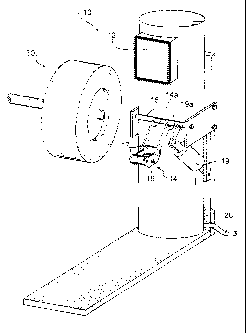
[0048] FIGS. 1-4 generally disclose a tire buffing machine 10 that is adapted
to
remove tread from a tire according to the methods, computer programs and
apparatus of
particular embodiments of the present invention. More specifically, the
buffing machine 10 is
adapted to buff the tread from a tire at a selected buff radius, the buff
radius being defined by its
length and the position of its origin. The buffing machine 10 generally
includes a tread removal
tool or buffing head 12, a sensor assembly 14, a sensor output 26, a
programmable logic
controller 20 or other device having a processor that can execute programmed
instructions, such
as, for example, a personal computer or main frame computer, and a user
interface 28. The
buffing head 12 removes tread material 32 from the crown of the tire 30, and
may comprise any
device capable of removing tread from a tire, including, without limitation,
abrading devices,
such as rasps, grinding wheels, and wire brushes, and cylindrical cutters or
"peelers."
[0049] Optionally, as known in the art, the buffing machine 10 may also
include one or
more buffing heads 12. A buffing machine having a single buffing head 12 is
cornmonly
referred to as a single head buffing machine, while a buffing machine having
two buffing heads
12 is referred to as a dual head buffing machine. It is contemplated that the
buffing head 12 may
be used to remove any material other than tread 32, such as for example,
undertread, which is
generally elastomer that is located between the belts 34 and the tread 32.
However, it is noted
that the present invention may be implemented on any type of buffing machine
that removes
tread 32 from a tire 30 along an arc described by a buffing radius.
[0050] The sensor assembly 14 is generally used to measure the amount of
material
above the tire belt 34. Such material generally includes the tire tread 32,
but may include other
material, such as for example undertread. In the embodiment shown, the sensor
assembly
includes a frame 16, a pair of rollers 17, the sensor 18, and arms 14a for
connecting the frame 16
to the shaft 15. In the embodiment shown, the shaft 15 rotates so that the
sensor assembly 14
may engage and disengage the tire 30. A cylinder 19 with rotation arms 19a may
be used to
rotate the shaft 15; however, it is also contemplated that any other rotation
means may be used to
rotate the shaft 15, including without limitation a manual lever or a motor.
It is also
CA 02690522 2009-12-10
WO 2009/002344 PCT/US2007/072376
contemplated that in alternate embodiments, the rotation means 19 may also
rotate the arms 14a
about a static shaft 15 or even that the arms 14a be replaced with only one
ann.
[0051] In particular embodiments, as shown in FIG. 1, the sensor 18 is
operably
mounted in a fixed relation to the buffing head 12 and scans or measures the
amount of material
remaining above the belts 34 after the buffing head 12 has buffed the tread
(i.e., while the tire is
spinning and the buffing head 12 is buffing). Being operably mounted in a
fixed relation to the
buffing head describes that the sensor, when operating, is located at a
constant relationship to the
buffing head. When the contact between the buffing head and tire crown moves
along the arc
described by the buffing radius, the sensor moves along in a fixed position to
the buffing head.
On a buffing machine having a buffing head that pivots about a mechanical
pivot point, then the
sensor may be mounted on the pivoting member so that the sensor mounting moves
with the
buffing head as the buffing head pivots. On a buffing machine having a buffing
head mounted
on a pedestal that moves along an X-Y coordinate system, then the sensor may
be mounted on
the pedestal so that the sensor mounting moves with the buffing head as the
buffing head moves
along the X-Y coordinate system.
[0052] Because the buffing machine 10 is controlled by the controller 20 to
buff the
tire along an arc described by the buff radius, one having ordinary skill in
the art will readily
realize that the location of the sensor 18 can easily be determined because of
the senor 18 is
operably mounted in a fixed relation to the buffing head 12. Since the
controller 20 can
determine exactly where the buffing head 12 is in relation to the centerline
of the tire 36 as it
controls the area of contact between the buffing head 12 and the tire 30, the
controller 20 can
determine the location of the sensor 18 that is in an operably fixed relation
to the buffing head 12
by the use of simple trigonometric and/or math functions. In this manner, the
controller 20 can
determine each of the plurality of transverse locations from which it receives
the signals from the
sensor 18.
[0053] Of course in other embodiments, it is contemplated that the sensor
assembly 14
and/or the sensor 18 may be independent of the buffing head 12 and/or may be
located on a
device or machine independent of, or other than, the buff machine 10. In those
embodiments, a
servo device, for example, can move the sensor across the tire and provide
input into the
11
CA 02690522 2009-12-10
WO 2009/002344 PCT/US2007/072376
controller 20 as to the location of the sensor relative to the centerline 36
of the tire. Such devices
are well known and are fully described in U.S. Patent No. 6,386,024.
[0054] Alternatively, in other embodiments, the sensor may be a series of
individual
sensing devices mounted in fixed relation to the rotating tire. For example, a
first sensing device
may be mounted above the crown at the centerline 36, a second and third
sensing devices
mounted at a fixed distance on either side of the first sensing device and so
forth. This series of
sensing devices is an exemplary embodiment of a sensor (collection of sensing
devices)
providing a signal from each of a plurality of transverse locations (the
location of each of the
sensing devices) across a portion of the tire crown, the sensor scanning a
transverse path across
the crown of the tire.
[0055] The sensor 18 is generally located radially above or outward from the
tread 32
and may or may not be located at an offset distance 40 above the tire tread
32. The sensor 18
may comprise an ultrasonic, magnetic or inductive proximity sensor for
measuring the distance
between sensor 18 and belt 34. However, it is contemplated that any other
sensor type may be
used, including those capable of locating non-ferrous cord material. For a
single head buffing
machine, a single sensor may be associated with the single buffing head 12. A
dual head buffing
machine may include two sensors, with each sensor being associated with one of
the buffing
head 12.
[0056] For a single head buffing machine 10, the buffing head 12 and the
sensor 18
may begin the buffing and scanning process at the tire centerline 36 and
continue to one of the
tire shoulders (L e., one side of the tire tread) for a first pass. After
making the initial pass, the
buffing head 12 and the sensor 18 may return to the tire centerline 36 to
begin a subsequent pass
for buffing and scanning the other half of the tire tread 32. Since the
buffing of the tire tread 32
is typically symmetrical about the tire centerline 36, the method that
includes the step of
determining a new buff radius origin position may perform that step for each
buffing pass. It is
also contemplated that the buffing head 12 and the sensor 18 may begin the
initial pass at a
shoulder or side of the tire, and then buff and scan across the tire tread to
the other shoulder or
side, thereby buffing and scanning the tire tread in a single pass. It is
contemplated that
particular embodiments of methods that include determining a new buff radius
origin position
may be performed during or after each pass.
12
CA 02690522 2011-11-25
[0057] The sensor 18 generates a signal response as a function of the
distance 42 between the sensor 18 and the tire belt 34. The signal response
may be
represented by a value, which may represent current, voltage, resistance, or
any
other characteristic of the signal response. Ultimately, the signal is sent to
the
programmable logic controller 20 by way of input/output (I/0) cable 26 for
evaluation
and processing.
[0058] The controller 20 interprets the received signal as a distance between
the belt 32 and the sensor 18. If the sensor is in substantial contact with
the tread
outer surface, the signal generally represents the thickness of the material
above
belt 34. If the sensor is an offset distance from the tread 32, the material
above belt
34 equals the distance measured by the sensor minus the offset distance 40.
Without limitation, the signal may also be sent by wireless communication to
controller 20, such as without limitation by infrared signal or radio
frequency, by one
or more cables, including without limitation fiber optics, or any other method
or
means known to those having ordinary skill in the art.
[0059] Programmable logic controller 20 generally receives signal responses
from sensor 18 to monitor and help control the amount of tread 32 being
removed
from tire 30. In a known way, the controller 20 manipulates the buffing head
12
and/or the tire 30 so that the buffing head 12 contracts and buffs the tire 30
along the
arc described by the buffing radius. In particular embodiments of the present
invention, the controller 20 further interprets the signals received from the
sensor 18
as the measured distance between the tread surface 32 and the belts 34.
[0060] In particular embodiments, the controller 20 may utilize signal-
distance
functions or tables (i.e., signal response curves 38 as shown in FIG. 5 to
convert a
signal response into a corresponding distance, such as the signal response
curves
disclosed in PCT Application No. PCT/US07/65522, filed March 29, 2007.
Controller
20 includes a logic processor 21, which may be a microprocessor, a memory
storage
device 22, such as RAM (random access memory), ROM (read-only memory),
PROM (programmable read-only memory) and at least one input/output (I/0) cable
13
CA 02690522 2011-11-25
26 for communicating with the buffing machine 10. Further, the controller 20
may
include an I/0 slot 23 for housing an I/0 card having I/0 cable connector 27.
An
operator may utilize a user-interface 28 to monitor the sensor measurements
and to
program, or otherwise control or instruct, __________________________________
20
13a
CA 02690522 2009-12-10
WO 2009/002344 PCT/US2007/072376
the operation of controller 20 and the buffing machine 10, which includes
performing each step
and method associated with determining a new or corrected buff radius origin
position as
detailed below. The user-interface 28 and the controller 20 may communicate by
way of I/0
cable 27. It is also contemplated that wireless communications may exist
between the controller
20, the user-interface 28, and the buffing machine 10.
0061] Generally, the controller 20 may be programmed by any known graphical or
text language. Programmed instructions, data, input, and output may be stored
in a memory
storage device 22, which is accessible to the processor 21. Particularly,
programmed instructions
related to the methods disclosed herein may be stored in the memory storage
device and
executed by the processor 21. The memory device 22 may comprise any
commercially known
storage device, such as hard disk drives, optical storage devices, flash
memory, and the like. The
processor 21 executes programmed instructions and may perform the distance
calculations and
measurements, and execute the instructions pertaining to the methods disclosed
herein as well as
other operations discussed herein. The memory storage device 22 also stores
inputs, outputs, and
other information, such as, for example, functions and tables representing
signal response curves
38 for use by processor 19 in performing its operations. In addition to
performing distance
conversions and measurements, the controller 20 may also be programmed to
generate signal
response curves 38, which may also be expressed as tables 39, based upon
received input.
[0062] With reference to FIGS. 5 and 5A, signal response curves 38 may be used
by
the controller 20 to convert signal responses received from the sensor 18 into
distances. The
signal response curves 38 are generally functions of the distance 42 between
the sensor 18 and
belt 34, and relate a signal response to a distance. The signal response
curves 38 may be stored
in a memory storage device 22 as a function or as a table. The processor 21
utilizes a desired
signal response curve to determine the distance corresponding to the signal
received.
[0063] More specifically, in an exemplary embodiment, the distance is
deteimined
from a function that represents signal response curve 38, which may be linear
or non-linear. In
another embodiment, the distance is determined from a table 39 that represents
signal response
curve 38, by locating from the table the two signal responses closest in value
to the signal
response received and then obtaining a linear relationship between the two
signal responses and
their corresponding distances. From the linear relationship, a distance is
determined for the
14
CA 02690522 2009-12-10
WO 2009/002344 PCT/US2007/072376
signal response received. The linear relationship may comprise a linear
function or may be
based upon a percentage or ratio relating the signal received to range between
the two points
selected from the table. If, by chance, the signal response received is
substantially equivalent to
a signal response within a table 39, the corresponding distance may also
represent the distance of
the received signal response.
[0064] Because signal responses may vary from tire to tire, a plurality of
signal
response curves 38 may be provided in exemplary embodiments, where each
response curve 38
represents a tire or a plurality of tires sharing a common tire
characteristic, such as, for example,
a tire size, shape, construction, manufacturer or brand, or a tread profile,
Consequently, to more
accurately control tread measurement and removal, the processor 21 selects a
signal response
curve 38 based upon a known tire characteristic, or based upon certain
information or
instructions received from an operator. Signal response curves 38, as
functions or as tables 39,
are generally stored in a memory storage device 22 and used by the processor
21 to determine
the distances according to programmed instructions reflecting the above stated
methods.
[0065] Referring generally to FIGS 6-16, the tire buffing machine 10 may buff
the
tread 32 of the tire 30 at one or more buff radii 46-48 (FIG. 6). Each buff
radius includes a
length and an origin 46a-48a, which is located along centerline 36. When the
tire tread is buffed
at a particular buff radius, the tread outer surface forms a curve or arc that
is described by the
buff radius 48. In the figures, buff radius 48 represents an initial (or
previous) buff radius having
an origin 48a. The other buff radii 46, 47 shown represent trial or proposed
buff radii each
having respective origins 46a, 47a, which can be examined to determine whether
one of these
proposed radii will provide a desired amount of material above the belt 34
after buffing. As
disclosed herein, particular embodiments of the present invention use these
proposed buff radii to
calculate a projected amount of tread that would have been removed had the
proposed buff radii
been used.
[0066] The sensor 18 may be used to scan the tread 32 at a plurality of
transverse
locations across at least a portion of the tire crown, and measure at each
location the distance
between the sensor 18 and the belt 34, before or after a first buffing pass by
the buffing head 12.
When preparing a tire for retreading, it is desirable to have a substantially
consistent thickness of
tread across the belt width and/or a minimal amount of material remaining
above the belt 34.
CA 02690522 2009-12-10
WO 2009/002344 PCT/US2007/072376
[0067] In one exemplary embodiment, as shown in FIG. 6, a tire 30 may
initially be
buffed at an initial buff radius 48 having an origin 48a positioned as shown
on the centerline 36.
Concurrently with the initial buff, the sensor 18 may scan the tire tread 32
of the crown and
generate response signals at a plurality of locations 1-5 across a portion of
the tread 32_ The
plurality of locations 1-5 may or may not occur at constant increments across
the tread. Further,
the sensor 18 may scan the tread (i.e., generate signals) along a particular
transverse path across
the tread, in which a single signal is generated at multiple locations across
the particular
transverse path. In other words, the transverse path coincides with a cross-
section of the tire
normal to the centerline 36 of the tire. To achieve this, a trigger or timing
function may be used
to unsure that sensor 18 scans along the path while the tire is rotating. A
trigger may comprise
any known device or method, including without limitation any encoder or
proximity sensor
known to one having ordinary skill in the art. A proximity sensor may utilize
an object, such as
a metal object (a block, screw, or the like) that is attached to the tire or
rim to initiate a scan that
is to be taken along a specific transverse path.
[0068] As an alternative to scanning along a transverse path or scanning
arbitrarily
around the tread circumference, the sensor 18 may generate multiple signals
around the tire at
each transverse location or between transverse locations, for the purpose of
obtaining an average
measurement at each such location or range along the tire tread. Because the
tire belt 34 may
vary at its outer edges, it may be desirous to only scan only a portion of the
tread, for example,
only the inner 80 % of the tread width, for the purpose of determining the new
buff radius and/or
new position for the origin of the buff radius, which then may be used to buff
the tire.
[0069] After scanning the crown of the tire 30, the controller 20 may
interpret the
signals it receives from the sensor 18 into the measured distances 42 between
the sensor 18 (or
tread surface) and the belts 34. For subsequent analysis and comparison, the
measured distances
42 may or may not be converted to represent the thickness of the material 44
remaining above
the belt 34, which is achieved by subtracting from the measured distances 42
the offset distance
between the sensor 18 and the crown tread 36, if any offset exists.
[0070] Subsequent to obtaining the measured distances, the measured distances
may be
compared to a target distance, which is typically the thickness of the rubber
at the location 1 of
the centerline 36 of the tire, though the target may be selected by any
criteria relevant to a given
16
CA 02690522 2009-12-10
WO 2009/002344 PCT/US2007/072376
application. The target distance generally reflects the result that was
targeted with the initial buff
radius 48. It is contemplated, however, that the target distance may reflect
the distance desired
from a subsequent buff pass.
[0071] Due, for example, to the inherent inconsistency of elastomeric
material,
machine wear, variation in machine components and the weight of the tire, any
buff may not
achieve the desired results. Consequently, a tire tread may be buffed at a
buff radius having its
origin at a position that ultimately provides a buffed surface contour that
varies from that which
was desired. This deviation may be symmetric or asymmetric about tire
centerline 36. If the
deviation is symmetric, that is, if the buffed contour is substantially
centered along the tread
width, correction of the symmetrically deviated buff may be achieved by moving
the origin
position of the buff radius along the tire centerline 36. If the deviation is
asymmetric about
centerline 36, correction of the asymmetrical deviation may be achieved by
moving the origin of
the buff radius transversely in relation to the tire or the tire centerline
36. It contemplated that
both corrections may occur simultaneously, that is to say that the position of
the origin of the
buff radius may be moved (1) vertically in relation to the tire crown (i.e.,
closer or further from
the tire tread 32 along the centerline 36), and/or (2) horizontally or
transversely in relation to the
tire crown (i.e., tire side-to-side normal to the centerline 36).
[0072] Such adjustment to the location of the origin of the buff radius will
result in a
flatter or steeper buffing arc (if the origin is moved along the centerline at
a constant radius
length) or in an off-centered (shifted) arc (if the origin is moved normal to
the centerline at a
constant radius length). Then, of course, the radius length may be shortened
and buffed with the
new origin position if the desire is to remove additional rubber across the
crown of the tire at a
steeper, flatter and/or off-centered arc as compared to the first or previous
buff.
[0073] Particular embodiments of the present invention may include the step of
determining whether the buff radius that was used on a buffing pass of the
tire is correct or if the
buffing operation resulted in an asymmetrical buff, a symmetrically deviated
buff or
combinations thereof. This determination may be made, for example, by
comparing the
differences between the measurements determined from the sensor readings
received from each
of the plurality of transverse locations across the crown of the tire. The
differences may be
between the measurements themselves or between the measurements and a target.
The target
17
CA 02690522 2009-12-10
WO 2009/002344 PCT/US2007/072376
may be the measurement taken at or near the centerline or any target value
suitable for a
particular application.
[0074] As shown in FIGS. 6-14, particular embodiments of the present invention
include calculating a difference between the measured distances and a target
distance and
between the projected distances and the target distance. The measured distance
is the distance
measured by the sensor at each of the plurality of transverse locations across
the tire crown.
Such measured distances may result, for example, from a buffing operation
performed with a
first buff radius 48 having a first origin position 48a located on the tire
centerline 36. The
projected distance is the distance that would have resulted had the buffing
operation been
performed with a proposed buffing radius 46, 47 having a proposed buffing
origin location 46a,
47a. Such proposed distances may result, for example from a first proposed
origin position 46a
for the first proposed buff radius 46.
[0075] Particular embodiments of the present invention provide progressing
through a
series of iterations of selecting a plurality of proposed origin positions
46a, 47a for proposed
buff radii 46, 47 and calculating the projected distance between the crown
surface and the belt at
each of the plurality of transverse locations across the crown, wherein each
projected distance is
based upon the arc described by a buffing radius having the one or more
proposed origin
positions. The result provides a plurality of projected distances compared to
the measured
difference from which a new buff radius position may be selected. Such
selection may be made
by use of a statistical analysis, such as a least squared method, as described
below. Therefore,
particular embodiments of the present invention further include the step of
choosing the new
origin position through statistical analysis of calculated differences between
the measured
distances and a target distance and calculated differences between the
projected distances and the
target distance, the differences being calculated for each of the plurality of
transverse locations.
[0076] The calculation of the projected distance may be rnade by the same
techniques
and calculations that are used to control the buffing operation through an arc
described by the
buffing radius. Since the controller 20 knows where the buffing head 12 is
located, for example
in the X-Y field, at each of the plurality of transverse locations reported on
by the sensor 18, then
the controller 20 can calculate where the buffing head 12 would have been in
the X-Y field at
each of the plurality of locations for each of the proposed origin positions
and/or buffing radius
18
CA 02690522 2009-12-10
WO 2009/002344 PCT/US2007/072376
lengths (proposed buff). The difference between where the buffing head would
have been at the
proposed buff and where it was in the actual buffing pass provides the
increased (positive
difference) or decreased (negative difference) thickness of the material above
the belts at the
proposed buff. This difference, when added to the measured distance, can
provide the projected
distance at each of the transverse locations for the proposed buff.
[0077] FIG. 7 is a table that provides the measured thickness at each of the
plurality of
transverse locations across the outboard side of the tire as shown in FIG. 6.
The table indicates
that the thickness at the centerline (7 mm) is greater than the thickness away
from the centerline
(6.5 mm), thereby indicating that the buff was symmetrically deviated, since
the other side of the
tire had symmetrical results (not shown). The target for the buff was 7 mm and
the differences
between the measured thickness and target was calculated. The sum of the
squares (1.08) of
these differences was also calculated for the statistical method for choosing
the next buffing
radius.
[0078] FIG. 8 is a table that provides the projected distance or thickness at
each of the
plurality of transverse locations across the outboard side of the tire as
shown in FIG. 6. The table
indicates that for the given iterated buff radius, for example the first
proposed buff radius 47
having an origin position 47a, the calculated projected distance was 7 mm at
the centerline and
almost 7 (6.8 mm) at the location 5 away from the centerline. The buff target
remains the same
and the differences and sum of the squares (0.06) were calculated. Since the
sum of the squares
is less, this proposed buff is an improvement over the initial buff.
[0079] The iterated selections of buff radius length and/or buff radius
origin position
may be made by any technique known to one having ordinary skill in the art.
For example, the
iterated buff radius may be selected arbitrarily or from a table of iterated
buff radii, which may
be stored in the memory of the controller 20, or any of its components.
Alternatively, the
iterations may be calculated, such as by controller 20 or any of its
components, based upon the
initial buff radius, the target distances, and/or the calculated differences.
Particular embodiments
of the present invention include selecting a plurality of buff radii and/or
buff radii origin
positions for evaluation as demonstrated above. The best of the proposed
buffing origin
positions/buffing radii can then be selected for subsequently buffing the tire
in the next buffing
pass. Such selection may be made, as shown above, by a least squares
technique.
19
CA 02690522 2009-12-10
WO 2009/002344 PCT/US2007/072376
[0080] FIGS. 10 and 11 provide the same analysis for FIGS. 7 and 8. Such
examples
are provided for embodiments of methods that buff neither asymmetrically nor
symmetrically
deviated but buff normally. If it is determined that the initial buff radius
provides fairly
consistent differences across the measured crown, that is the tread thickness
may be fairly
uniform but the thicknesses may not be that which was intended or desired, the
length of the buff
radius may be adjusted to correct for the difference or offset without
changing the origin
location, or the origin location may be moved along centerline 36 with the
radius length kept
constant to correct for the difference.
[0081] FIGS. 12-14 illustrate the correction of an asymmetrical buff. As shown
in
FIG. 13, the buff was asymmetrical because the after-buff measured distances
at the locations 6-
9 on the outboard side of tire are all less than 7 mm while those at locations
1-4 on the inboard
side of the tire are all greater than 7. While the target value is shown as
being 7 mm, the sum of
the squared differences was 0.0671.
[0082] FIG. 14 is a table that provides the projected distance or thickness at
each of the
plurality of transverse locations across the tire as shown in FIG. 12. The
table indicates that for
the given iterated buff radius, for example the first proposed buff radius 47
having an origin
position 47a which is located at a position normal to the centerline 36, the
calculated projected
distance was 7.01 nun at the centerline and almost 7 (6.92 mm) at the outboard
location 9 and
7.11 at the inboard location 1. The buff target remains the same and the
differences and sum of
the squares (0.0324) are calculated. Since the sum of the squares is less,
this proposed buff is an
improvement over the initial buff
[0083] A plurality of iterated origin points may be selected and evaluated as
disclosed
above before choosing a new origin point at which to subsequently buff the
tire. When
determining if the differences indicate whether the buff is asymmetric, a
portion of the tread may
be evaluated on both sides of centerline 36 or on a single side of centerline
36. Further, it is
contemplated that a new buff radius and origin may be selected from the
distances measured and
projected, by determining therefrom the amount of material remaining above the
belt across the
tread of the tire. By plotting such a curve, the apex or peak of the curve
(i.e., the point along the
curve where the tangent is perpendicular to centerline 36) or the origin can
be determined, and
CA 02690522 2009-12-10
WO 2009/002344 PCT/US2007/072376
therefrom, the distance from which either located laterally from centerline 36
(the "offset
distance") can be determined.
[0084] If the apex or origin is located at centerline 36, then the buff is
generally
symmetric. If the apex or origin is located a lateral distance from centerline
36, the origin point
may be moved such distance closer to centerline 36 to provide a more symmetric
subsequent
buff. Once learning the offset distance, the origin can be moved such distance
to the centerline
36 to re-center the buff radius on the tire tread. However, additional
projected buff radius origins
may be selected through iteration providing a better fit with a smaller sum of
the squares.
[0085] FIG. 15 is a flow chart. of a method for correcting a buff of tread
from a tire, in
accordance with an embodiment of the present invention. States 102 through 110
describe the
steps of a particular embodiment of the invention.
[0086] While this invention has been described with reference to particular
embodiments thereof, it shall be understood that such description is by way of
illustration and
not by way of limitation. Accordingly, the scope and content of the invention
are to be defined
only by the terms of the appended claims.
21