Note: Descriptions are shown in the official language in which they were submitted.
CA 02691018 2010-01-26
LED OPTICAL ASSEMBLY
100011 Not Applicable.
TECHNICAL FIELD
100021 This invention pertains generally to an optical assembly, and more
specifically to
an LED optical assembly.
BRIEF DESCRIPTION OF THE ILLUSTRATIONS
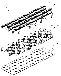
100031 Figure 1 is an exploded perspective view of a first embodiment of
the LED optical
assembly of the present invention.
100041 Figure 2 is a top perspective view of a first embodiment of an
optical lens of the
LED optical assembly of Figure I exploded away from a reflector of the LED
optical
assembly of Figure 1.
100051 Figure 3 is a bottom perspective view of the optical lens of Figure
2 coupled to
the reflector of Figure 2.
100061 Figure 3A is a bottom perspective view of the optical lens of Figure
2 coupled to
the reflector of Figure 2, shown with the reflector positioned about a light
emitting diode.
100071 Figure 4 is a bottom perspective view of the optical lens of Figure
2.
[00081 Figure 5 is a side view, in section, of the optical lens and
reflector of Figure 3
taken along the section line 5-5 of Figure 3.
100091 Figure 6 is a bottom perspective view of a second embodiment of an
optical lens
of the LED optical assembly of the present invention.
CA 02691018 2010-01-26
100101 Figure 7 is a bottom perspective view of a third embodiment of an
optical lens of
the LED optical assembly of the present invention.
100111 Figure 8 is a side view of the optical lens and reflector of Figure
3 taken along the
line 5-5 and shown positioned about a LED with a ray trace of exemplary light
rays that
emanate from the LED.
100121 Figure 9 is a top perspective view of a fourth embodiment of an
optical lens of the
LED optical assembly of the present invention shown coupled to a reflector of
the LED
optical assembly of Figure 1.
100131 Figure 10 is a side view, in section, of the optical lens and
reflector of Figure 9
taken along the section line 10-10 of Figure 9.
[0014] Figure 11 is a top perspective view of a second embodiment of a
reflector bank of
the LED optical assembly of the present invention.
100151 Figure 12 is a bottom perspective view of the reflector bank of
Figure 11.
100161 Figure 13A is a polar distribution, scaled in candela, of a single
light emitting
diode with its light output axis aimed approximately seventy five degrees off
nadir in a
vertical direction and with a reflector of Figure 1 about the light emitting
diode and the
second embodiment of the optical lens of Figure 6 coupled to the reflector.
[0017] Figure 13B is a polar distribution, scaled in candela, of a single
light emitting
diode with its light output axis aimed approximately seventy five degrees off
nadir in a
vertical direction and with a reflector of Figure 1 about the light emitting
diode and the
first embodiment of the optical lens of Figure 4 coupled to the reflector.
[0018] Figure 13C is a polar distribution, scaled in candela, of a single
light emitting
diode with its light output axis aimed approximately seventy five degrees off
nadir in a
CA 02691018 2010-01-26
vertical direction and with a reflector of Figure 1 about the light emitting
diode and the
third embodiment of the optical lens of Figure 7 coupled to the reflector.
100191 Figure 14 is a perspective view of a second embodiment of the LED
optical
assembly of the present invention with a reflector plate and a cover lens
exploded away.
100201 Figure 15 is a side view of the LED optical assembly of Figure 14.
100211 Figure 16 is a bottom perspective view of a LED luminaire having two
of the
LED optical assemblies of Figure 14.
100221 Figure 17 is a top perspective view of the LED luminaire of Figure
16, with
portions exploded away.
DETAILED DESCRIPTION
100231 It is to be understood that the invention is not limited in its
application to the
details of construction and the arrangement of components set forth in the
following
description or illustrated in the drawings. The invention is capable of other
embodiments
and of being practiced or of being carried out in various ways. Also, it is to
be
understood that the phraseology and terminology used herein is for the purpose
of
description and should not be regarded as limiting. The use of "including,"
"comprising," or "having" and variations thereof herein is meant to encompass
the items
listed thereafter and equivalents thereof as well as additional items. Unless
limited
otherwise, the terms "connected," "coupled," "in communication with" and
"mounted,"
and variations thereof herein are used broadly and encompass direct and
indirect
connections, couplings, and mountings. In addition, the terms "connected" and
"coupled" and variations thereof are not restricted to physical or mechanical
connections
or couplings. Furthermore, and as described in subsequent paragraphs, the
specific
3
CA 02691018 2016-06-23
56146-165
mechanical configurations illustrated in the drawings are intended to
exemplify
embodiments of the invention and that other alternative mechanical
configurations are
possible.
[0023a] According to one aspect of the present invention, there is
provided an LED
optical assembly comprising: a support surface having a plurality of light
emitting
diodes; a plurality of reflectors forming a reflector bank and mounted on said
support
surface, each of said plurality of reflectors positioned over one of said
plurality of light
emitting diodes; a plurality of optical lenses forming an optical lens bank,
said optical
lens bank removably coupled to and positioned over said reflector bank such
that each
of said plurality of optical lenses is positioned over one of said plurality
of reflectors,
and wherein a cutoff prism extends from at least one of said plurality of
optical lenses
in a direction outward and away from said support surface.
[0023b] According to another aspect of the present invention, there is
provided an LED
optical assembly comprising: a support surface having a plurality of light
emitting
diodes, each of said plurality of light emitting diodes having a light output
axis
oriented outward and away from said support surface; a plurality of reflectors
adjacent
said support surface, each of said plurality of reflectors positioned over one
of said
light emitting diodes and being a bi-focal reflector with a first reflector
portion having
a first curvature and a second reflector portion having a second curvature,
said first
curvature being more gradual than said second curvature; a plurality of
optical lenses,
at least one of said plurality of optical lenses being positioned over one of
said
reflectors, and at least one of said plurality of optical lenses having at
least one cutoff
prism extending from a portion thereof, each said cutoff prism extending in a
direction
outward and away from said support surface.
[0023c] According to another aspect of the present invention, there is
provided an LED
optical assembly comprising: a support surface having a plurality of light
emitting
diodes mounted thereon; a plurality of reflectors affixed together to form a
reflector
bank, said reflector bank mountable on said support surface such that each
reflector is
aligned over a single of said plurality of light emitting diodes; a plurality
of optical
4
CA 02691018 2016-06-23
' 56146-165
lenses forming a lens bank, said lens bank affixed to said reflector bank such
that at
least one of said plurality of optical lenses is mounted over at least one of
said plurality
of reflectors; wherein each of said plurality of reflectors is a bi-focal
reflector with a
first reflector portion and a second reflector portion, said first reflector
portion having
a first curvature and said second reflector portion having a second curvature,
said first
curvature being more gradual than said second curvature.
[0024] With reference to Figure 1, a first embodiment of an LED
optical assembly 10
has a light emitting diode (LED) assembly or LED circuit board 30, a reflector
bank
50, and an optical lens bank 70. The terms "LED" and "light emitting diode" as
used
herein are meant to be interpreted broadly and can include, but are not
limited to, an
LED of any color, any luminosity, and any light distribution pattern, and also
includes,
but is not limited to, an organic light emitting diode (OLED), among others.
The
embodiment of LED assembly 30 shown has thirty LEDs 34 mounted on LED support
surface 32. In some embodiments LEDs 34 may be XLampTM XR-E Cool White
LEDs from Cree, Inc. In other embodiments LEDs 34 may be XLampTM XP-E Cool
White LEDs from Cree, Inc. However, any LED configuration may be implemented
in the presently described assembly.
[0025] In some embodiments of LED support surface 32, LED support
surface 32 is a
metallic board with advantageous heat distribution properties such as, but not
limited
to, aluminum. In some embodiments LED support surface 32 is an Aluminum
support
board from Trilogix Electronic Manufacturing. In other embodiments LED support
surface 32 is a flame retardant 4 (FR-4) or other common printed circuit
board. LED
support surface 32 and plurality of LEDs 34 of LED assembly 30 are merely
exemplary of the multitude of boards, number of LEDs, and multitude of LED
configurations that may be used. Design considerations such as, but not
limited to,
heat generation, desired lumen output, and desired light distribution pattern
may result
in a choice of differing amounts
4a
CA 02691018 2010-01-26
of LEDs, differing LED configurations, and/or differing materials for LED
support
surface 32.
100261 Reflector bank 50 is shown with thirty individual reflectors 52,
each positionable
over a single LED 34. Optical lens bank 70 is shown with thirty individual
optical lenses
72, which may each be removably coupled over a light output opening of a
single
reflector 52. Although each LED 34 is shown with a corresponding reflector 52
and a
corresponding optical lens 72, in other embodiments of LED optical assembly 10
one or
more LEDs 34 may be provided without a corresponding reflector 52 and/or
optical lens
72. The number and configuration of reflectors 52 and optical lenses 72 arc
merely
exemplary and may be appropriately adjusted to interact with a differing
number or
configuration of LED support surfaces 32 and/or LEDs 34.
100271 With reference to Figure 2 through Figure 5, a first embodiment of a
single
optical lens 72 of Figure 1 and a single corresponding reflector 52 of Figure
1 are
described in more detail. In the embodiment of Figure 2 through Figure 5
optical lens 72
may be removably coupled to reflector 52. Two latches or connection pieces 85
of
optical lens 72 removably engage two corresponding latch receptacles or
connection
areas 65 of reflector 52. Connection pieces 85 in the embodiment of Figure 2
through
Figure 5 are cantilever latch members with a protrusion 87. With particular
reference to
Figure 5, when optical lens 72 is placed over reflector 52, protrusion 87
slides down
incline 66 until protrusion 87 reaches the end of incline 66 and engages base
67 of incline
66. Force can be applied against connection piece 85 by a finger, flat head
screwdriver,
removal tool, or other tool in order to disengage protrusion 87 from base 67
of incline 66
and allow optical lens 72 to be separated from reflector 52.
CA 02691018 2010-01-26
100281 Connection piece 85 and connection area 65 are merely exemplary of
a removable
coupling between optical lens 72 and reflector 52. For example, in other
embodiments
reflector 52 may be provided with a cantilever latch member connection piece
and optical
lens 72 may be provided with a corresponding latch receptacle connection area.
Also, for
example, in some embodiments the connection piece may comprise a male
protrusion
with one or more slots receivable in a connection area that comprises a female
receptor
with matching pins or slots. A removable coupling between optical lens 72 and
reflector
52 allows optical lens 72 to be exchanged for an optical lens having
alternative optical
characteristics or to allow optical lens 72 to be removed for cleaning or
replacement with
a clean optical lens. Although removable couplings between optical lens 72 and
reflector
52 have been described, in other embodiments optical lens 72 may be non-
removably
coupled to reflector 52, or optical lens 72 may be provided over reflector 52
without
being directly coupled to reflector 52.
100291 With continuing reference to Figure 2 through Figure 5, reflector
52 of the
depicted embodiment is a dual focal point reflector having a first reflector
portion 54 and
a second reflector portion 56. Two kick reflectors 55 extend between first
reflector
portion 54 and second reflector portion 56. In the depicted embodiment first
reflector
portion 54 is a substantially parabolic reflector having a first focal point
and second
reflector portion 56 is a substantially parabolic reflector having a second
focal point that
is distinct from the first focal point of first reflector portion 54. With
particular reference
to Figure 5, first reflector portion 54 has a more gradual curvature than
second reflector
portion 56. In other embodiments first reflector portion 54 and second
reflector portion
56 may be non-parabolic and still have distinct curvatures with distinct focal
points.
6
CA 02691018 2010-01-26
Dual focal points enable reflector 52 to appropriately direct light emitted by
LEDs 34
having different light distribution characteristics for reasons such as
manufacturing
tolerances. Dual focal points also enable reflector 52 to appropriately direct
light emitted
by LEDs having a different design that places the light emitting portion of
the LED in a
different location within reflector 52. In some embodiments reflector 52 is a
reflector
produced by GLP Hi-Tech and is made from Lexan 940 A which is then vacuum
metalized with Aluminum. In other embodiments reflector 52 may be vacuum
metalized
with other reflective materials such as, but not limited to, silver and/or
gold.
100301 With particular reference to Figure 3 and Figure 3A, an LED aperture
64 and a
recess portion are sized and shaped so that reflector 52 may be appropriately
positioned
about a given LED 34. In the depicted embodiment the recess portion and LED
aperture
64 are configured so that the LED light output axis of a given LED 34 will be
positioned
substantially in line with both the first focal point of First reflector
portion 54 and the
second focal point of second reflector portion 56. In the depicted embodiment
aperture
64 is large enough to receive the light emitting portion of LED 34 without
contacting
LED 34. In the depicted embodiment the recess portion has a generally
cruciform shape
with arms 62a, 62b, 62c, and 62d all of substantially equal dimension. The
distance
between the tip of arm 62a and the tip of ami 62b is substantially the same as
the distance
between the tip of arm 62c and the tip of arm 62d. The recess portion is
shaped and sized
to interface with a portion of an outer periphery of an LED that is
rectangular, such as,
but not limited to, the outer periphery of a single LED 34. In the exemplary
embodiment
reflector 52 may be placed about a single LED 34 so that the periphery of arms
62a and
62b contact or are substantially close to portions of the outer periphery of
LED 34 and the
7
CA 02691018 2010-01-26
periphery of arms 62c and 62d do not contact LED 34, or vice versa. Figure 3A
shows
LED 34 in contact with the periphery of arms 62a and 62b.
100311 It will be appreciated that the recess portion allows reflector 52
to be
appropriately aligned about a given LED 34 at any one of four orientations,
each
approximately ninety degrees apart. It is understood that for appropriate
alignment of
reflector 52 about an LED 34 it is not necessary that the periphery of arms
62a and 62b or
62c and 62d actually contact the outer periphery 34. Rather, a small gap may
exist
between the outer periphery of LED 34 and the periphery of 62a and 62b or 62c
and 62d
and satisfactory alignment may still be achieved. The recess portion allows
for unique
orientation of one or more reflectors 52 on LED support surface 32. The recess
portion
and/or aperture 64 may be adjusted appropriately to accommodate other shapes
and sizes
of LEDs and to appropriately position other LEDs with respect to reflector 52.
For
example, in some embodiments the recess portion may be configured to interface
with an
LED having a square outer periphery, in which case the recess portion may have
a
substantially square shape.
100321 In other embodiments the recess portion and aperture 64 may be
omitted and
reflector 52 may be robotically or otherwise positioned about a given LED 34.
An
adhesive layer 60 is provided exteriorly of recess portion 62 and aperture 64
in some
embodiments and may couple reflector 52 to LED support surface 32. Alternative
or
additional couplings between reflector 52 and LED support surface 32 may be
used. In
some embodiments reflector 52 may be attached using mechanical affixation
methods,
including, but not limited to prongs, fasteners, depending structures and the
like that
interface with corresponding structure on LED support surface 32. Also, this
8
CA 02691018 2010-01-26
interchangeably includes structure upwardly extending from LED support surface
32 that
corresponds with structure on reflector 52. Supports 63 may be provided to
help stabilize
reflector 52 and in some embodiments may be additionally adhered to LED
support
surface 32.
100331 In some embodiments first and second reflector portions 54 and 56
and the recess
portion of each reflector 52 are configured so that when reflector 52 is
placed about a
given LED 34, the LED light output axis of the LED 34 will emanate from a
point that is
between the dual focal points of reflector 52 or equal to one of the dual
focal points of
reflector 52. The LED light output axis is an axis emanating from
approximately the
center of the light emitting portion of any given LED 34 and is oriented
outward and
away from the LED support surface 32. Although two reflector portions 54 and
56 and
dual focal points are described herein, other embodiments of reflector 52 may
be
provided with more than two reflector portions and more than two focal points.
For
example, in some embodiments three reflectors are provided with three distinct
focal
points.
[0034] With particular reference to Figure 4 and Figure 5, the embodiment
of optical
lens 72 shown has prismatic areas 74 and 76 on a first surface of optical lens
72.
Prismatic areas 74 and 76 are separated by refracting bar 75. When optical
lens 72 is
coupled to reflector 52, prismatic area 74 is provided mainly over reflector
portion 54 and
aperture 64. Prismatic area 76 is provided mainly over reflector portion 56
and aperture
64. Refracting bar 75 is provided mainly over aperture 64 and portions of
reflector 56.
In some embodiments refracting bar 75 may be altered or omitted and prismatic
areas 74
and 76 may likewise be altered or omitted. Prismatic areas 74 and 76 direct
light
9
CA 02691018 2010-01-26
emanating from LED 34 and contacting prismatic areas 74 and 76 to a wider
angle along
a horizontal plane, as will be described in more detail herein. Refracting bar
75 directs
light emanating from LED 34 and contacting refracting bar 75 in a direction
generally
away from a face 84 of a cutoff element 80 having a cutoff surface 82.
Depending on
their angle of incidence, many light rays emanating from LED 34 and contacting
cutoff
surface 82 are either refracted through cutoff surface 82 in a direction
generally toward
the light output axis of LED 34 or are reflected off cutoff surface 82 and
directed toward
and through front face 84. In some embodiments, when optical lens 172 is
coupled to
reflector 52 and reflector 52 is placed about an LED 34 on LED support surface
32, the
distance between LED support surface 32 and non-prismatic areas 174 and 176 is
approximately .5 inches and the distance between LED support surface 32 and
the most
distal part of cutoff surface 182 is approximately 1.04 inches.
100351 In other embodiments of optical lens, such as optical lens 172 of
Figure 6,
refracting bar 175 separates two non-prismatic areas 174 and 176. Non-
prismatic areas
174 and 176 do not significantly alter the direction of light emanating from
LED 34 and
contacting prismatic areas 174 and 176 along a horizontal plane, as will be
described in
more detail herein. In other embodiments of optical lens, such as optical lens
272 of
Figure 7, refracting bar 275 separates two prismatic areas 274 and 276.
Prismatic areas
274 and 276 direct light emanating from LED 34 and contacting prismatic areas
274 and
276 in a first asymmetric direction along a horizontal plane, as will be
described in more
detail herein. In other embodiments prismatic areas 274 and 276 may be altered
to direct
light in a second asymmetric direction along a horizontal plane that is
substantially
opposite the first asymmetric direction, as will be described in more detail
herein. In the
CA 02691018 2010-01-26
embodiments of Figure 6 and Figure 7, refracting bars 175 and 275 may be
altered or
omitted. Moreover, in some embodiments one or more of the prismatic areas
described
may be altered or omitted.
100361 In some embodiments optical lenses 72, 172, and 272 are produced by
GLP Hi-
Tech and are made from Acrylic V825, having a refractive index of
approximately 1.49.
Optical lenses 72, 172, and 272 are all configured to be removably coupled to
the same
reflector 52. As a result, optical lenses 72, 172, and 272 can be selectively
coupled to an
individual reflector 52 of reflector bank 50 to achieve a desired light
distribution. In
some embodiments prismatic lenses 272 may be coupled to reflectors 52 on edges
of a
reflector bank 50 so they may asymmetrically direct light to the edges of an
illumination
area. In some embodiments prismatic lenses 72 may be coupled to reflectors 52
proximal
the edges of a reflector bank 50 to provide a wide dispersion of light
proximal to the
edges of an illumination area. In some embodiments prismatic lenses 172 may be
coupled to reflectors 52 proximal the inner portion of a reflector bank 50 to
provide a
more narrow dispersion of light near the center of the illumination area.
Other
arrangements of optical lenses 72, 172, and 272 may be used to achieve desired
light
distribution characteristics.
[0037] With reference to Figure 8, a single reflector 52 is shown about a
single LED 34
with a single optical lens 72 placed over reflector 52. Many reference numbers
have been
omitted in Figure 8 for simplicity. Reference may be made to Figure 5 for
identification
of unlabeled parts in Figure 8. Ray traces of exemplary light rays that
emanate from
LED 34 are shown. An LED light output axis is also shown designated by
reference
letter "A". LED light output axis A is shown for exemplary purposes only, does
not
CA 02691018 2010-01-26
represent part of the ray trace, and as =a result is not shown as being
altered by optical lens
72. LED support surface 32 is shown disposed at an angle, a, that is
approximately
fifteen degrees off a line N. LED light output axis A is directed at
approximately a one-
hundred-and-five degree angle with respect to line N and approximately a
seventy five
degree angle with respect to nadir. In some embodiment LED light output axis A
may be
aimed at approximately a seventy five degree angle with respect to nadir to
maintain
appropriate cutoff and appropriately direct light downward to an illumination
area.
100381 Some light rays emanate from LED 34 and are directed toward first
reflector
portion 54. Many of those rays originate from a point substantially close to
the focal
point of first reflector portion 54 and are collimated by reflector 52 and
directed toward
cutoff surface 82. The rays are incident to cutoff surface 82 at an angle
larger than the
critical angle and are internally reflected toward and out front face 84.
Although front
face 84 is shown with ribs, in other embodiments front face 84 may be
relatively smooth
or otherwise contoured. Other light rays emanate from LED 34 and are directed
toward
cutoff prism 80 without first contacting first reflector portion 54. Many of
those rays are
incident to cutoff surface 82 at an angle smaller than the critical angle and
are refracted
through cutoff surface 82. Some of these same rays may be partially internally
reflected
toward and out front face 84 as shown. Other light rays emanate from LED 34
and are
directed toward refracting bar 75 without first contacting First reflector
portion 54 or
second reflector portion 56. The light rays are refracted in a direction
generally away
from front face 84 of cutoff prism 80. Other light rays emanate from LED 34
and arc
directed toward second reflector portion 56. Those rays are positioned below
the focal
point of second reflector portion 56 and are reflected by reflector portion 56
in a direction
CA 02691018 2010-01-26
generally away from front face 84 of cutoff prism 80. Those light rays are
also refracted
in a direction generally away from front face 84 of cutoff prism 80 as they
enter optical
lens 72 through prismatic area 74 and exit through face portion 78. Yet other
light rays
emanate from LED 34 and are directed toward prismatic area 74 without first
contacting
second reflector portion 56 and are refracted in a direction generally away
from front face
84 of cutoff prism 80 as they enter optical lens 72 through prismatic area 76
and exit
through face portion 78.
100391 The rays presented in Figure 8 are presented for exemplary purposes.
It is
understood that other rays may be emitted by LED 34 which may behave
differently as
they contact reflector 52 and/or optical lens 72. It is also understood that
prismatic
surfaces 74 and 76 will cause many rays to be directed at a wider angle in a
horizontal
plane and that this is not depicted in the side view of Figure 8. With
continuing reference
to Figure 8, all the light rays shown exiting optical lens 72 are directed in
a direction
along, or generally downward and away (as indicated by arrow D) from the light
output
axis A of LED 34. Although some light rays may exit optical lens 172 and be
directed
upward and away from the light output axis of LED 34, the light rays will be
minimal
compared to those directed along and downward and away from the light output
axis A of
LED 34. It will be appreciated that so long as the LED light output axis A is
substantially in line with the focal points of reflector portions 54 and 56
and light rays
from LED 34 emanate from a point that is between the dual focal points or
equal to one
of the dual focal points, a majority of light rays exiting optical lens 172
will be directed
along or downward and away (as indicated by arrow D) from the light output
axis A of
LED 34 and toward an illumination area.
13
CA 02691018 2010-01-26
100401 Figure 13A shows a polar distribution, scaled in candela, of a
single LED 34 with
its light output axis aimed approximately seventy five degrees off nadir in a
vertical
direction and with a reflector 52 of Figure 1 about LED 34 and optical lens
172 of Figure
6 coupled to reflector 52. Figure 13B shows a polar distribution, scaled in
candela, of a
single LED 34 with its light output axis aimed approximately seventy five
degrees off
nadir in a vertical direction and with a reflector 52 of Figure 1 about LED 34
and optical
lens 72 of Figure 4 coupled to reflector 52. Figure 13C shows a polar
distribution,
scaled in candela, of a single LED 34 with its light output axis aimed
approximately
seventy five degrees off nadir in a vertical direction and with a reflector 52
of Figure 1
about LED 34 and optical lens 272 of Figure 7 coupled to reflector 52.
100411 With reference to Figure 13A through Figure 13C, a majority of light
outputted by
LED 34 in a vertical plane, designated by reference letter "V", is directed
along or below
the light output axis of LED 34, which is aimed approximately seventy five
degrees off
nadir in a vertical direction. With reference to Figure 13A, in which optical
lens 172 is
used, a majority of light outputted by LED 34 in a horizontal plane,
designated by
reference letter "H", is directed substantially symmetrically within
approximately a fifty
degree range. With reference to Figure 13B, in which optical lens 72 is used,
a majority
of light outputted by LED 34 in horizontal plane H is directed substantially
symmetrically within approximately a seventy-five degree range. The wider
range in the
horizontal plane is a result of light contacting prismatic areas 174 and 176.
With
reference to Figure 13C, in which optical lens 272 is used, a majority of
light outputted
by LED 34 in horizontal plane H is directed asymmetrically within
approximately an
eighty degree range. The wider range in the horizontal plane and the
asymmetric
14
CA 02691018 2010-01-26
distribution is a result of light contacting prismatic areas 274 and 276. As
described
previously, prismatic areas 274 and 276 may be adjusted to asymmetrically
distribute
light in a substantially opposite direction to that depicted in Figure 13C.
Figure 13A
through Figure 13C are provided for purposes of illustration only. Of course,
other
embodiments may be provided that produce differing polar distributions that
direct light
in a differing range off of and away from the light output axis.
100421 With reference to Figure 9 and Figure 10, a fourth embodiment of an
optical lens
372 is shown coupled to a reflector 52 of the LED optical assembly 10 of
Figure 1.
Optical lens 372 has a cutoff prism 380. Cutoff prism 380 has five cutoff
surfaces 382a,
382b, 382c, 382d, and 382e with corresponding front faces 384a, 384b, 384c,
384d, and
384e. Light rays that emanate from an LED and contact cutoff surfaces 382a,
382b,
382c, 382d, or 382e are either refracted through the respective cutoff surface
382a, 382b,
382c, 382d, or 382e in a direction generally toward the corresponding front
face 384a,
384b, 384c, 384d, or 384e or are reflected off the respective cutoff surface
382a, 382b,
382c, 382d, or 382e and directed toward and through the corresponding front
face 384a,
384b, 384c, 384d, or 384e.
100431 With reference to Figure 11 and Figure 12, a second embodiment of a
reflector
bank 150 is shown. Reflector bank 150 is a unitary reflector bank and has
thirty
individual reflectors 152 with first and second reflector portions 154 and
156. Reflectors
152 are coupled to one another by connecting portion 151. Unitary reflector
bank 150
may be coupled to LED assembly 30 of Figure 1. Optical lenses may be modified
to be
placed over an appropriate reflector 152. Moreover, in some embodiments
optical lenses
may be coupled to one another to form a unitary optical lens bank that may be
coupled to
1 5
CA 02691018 2010-01-26
reflector bank 150. Also, unitary reflector bank 150 could be modified to
incorporate
connection areas with some or all reflectors 152 for removable coupling of
optical lenses
to reflectors 152.
[0044] With reference to Figure 14 and 15, a second embodiment of LED
optical
assembly 100 is shown having a LED assembly 30, a reflector bank 50, and an
optical
lens bank 70. LED assembly 30 is coupled to heatsink 20 which dissipates heat
generated by LED assembly 30. In the depicted embodiment heatsink 20 has
channels 22
for airflow and is constructed from aluminum. In other embodiments,
alternative heatsink
designs and materials may be used or heatsink 20 may be omitted altogether if
not needed
or desired for heat dissipation. A reflector plate 88 has a portion that
extends around
optical lenses 72 and a portion that extends generally away from and
substantially
perpendicular to LED support surface 32. The portion of reflector plate 88
that extends
generally away from LED support surface 32 redirects light incident upon it
generally
toward the area to be illuminated by LED optical assembly 100 and helps
maintain an
appropriate cutoff. Other portions of reflector plate 88 similarly reflect any
stray rays
generally toward the area to be illuminated by LED optical assembly 100. In
some
embodiments of LED optical assembly 100 reflector plate 88 may be constructed
form
aluminum. In some embodiments of LED optical assembly 100 reflector plate 88
may be
omitted. A cover lens 4 is also provided and may seal housing and/or alter
optical
characteristics of light passing there through. In some embodiments of LED
optical
assembly 100 cover lens 4 may be omitted.
[0045] With reference to Figure 16 and Figure 17, an LED luminaire 200 has
two LED
optical assemblies 100 coupled end to end to one another at an angle of
approximately
I 6
CA 02691018 2010-01-26
ninety degrees. A driver housing 95 encloses an LED driver 36 that provides
electrical
power to LEDs 34 of LED assembly 30 of each LED optical assembly 100. In some
embodiments LED driver 36 is a forty Watt power supply manufactured by Magtech
Industries. In other embodiments LED driver 36 is a sixty Watt power supply
manufactured by Magtech Industries. In yet other embodiments LED driver 36 is
a
ninety-six Watt power supply manufactured by Magtech Industries. Driver
housing 95
also helps to support LED optical assemblies 100 and connects them through arm
mount
90 to a support pole 2. Driver housing 95 has apertures 97 that correspond to
channels 22
in heatsink 20 and allow airflow into and out of channels 22. The light output
axes of
LEDs 34 are directed approximately seventy-five degrees off nadir.
100461 In some embodiments LED luminaire 200 may be configured to
achieve Type II
or Type III light distribution patterns. Driver housing 95, arm mount 90 and
support pole
2 are provided for exemplary purposes only. Also, the number of, orientation
of, and
configuration of LED optical assemblies 100 are provided for exemplary
purposes only.
For example, in other embodiments four LED optical assemblies 100 may be
placed
around a support pole to create Type IV or Type V light distribution patterns.
For
example, in other embodiments LED optical assemblies 100 may be coupled to a
wall or
other support surface rather than support pole 2. For example, in other
embodiments
LED optical assemblies 100 may be coupled directly to support pole 2 and
drivers for
LEDs 34 may be enclosed within support pole 2. Also, for example, in other
embodiments LED optical assemblies 100 may be placed at a different angle with
respect
to each other and/or light output axes of LEDs 34 may be placed at different
angles with
respect to nadir.
17
CA 02691018 2010-01-26
100471
The foregoing description has been presented for purposes of illustration. It
is not
intended to be exhaustive or to limit the invention to the precise forms
disclosed, and
obviously many modifications and variations are possible in light of the above
teaching.
It is understood that while certain forms of the LED optical assembly have
been
illustrated and described, it is not limited thereto except insofar as such
limitations are
included in the following claims and allowable functional equivalents thereof.