Note: Descriptions are shown in the official language in which they were submitted.
CA 02691034 2010-01-25
REDUCING ERROR CONTRIBUTIONS TO GYROSCOPIC MEASUREMENTS
FROM A WELLBORE SURVEY SYSTEM
BACKGROUND OF THE INVENTION
Field of the Invention
[0001] The present application relates generally to systems and 'method
for
reducing error contributions to gyroscopic measurements from a wellbore survey
system
and/or determining the position or orientation of the survey system relative
to the Earth.
Description of the Related Art
[0002] Many wellbore gyroscopic survey systems that are currently in
service are
based on angular rate measurements taken about two axes only, denoted the x
and y axes, that
are both substantially perpendicular to the direction along the wellbore
(referred to as the
"along-hole axis") and substantially perpendicular to each other. In
stationary gyroscopic
survey systems, these measurements are used to determine the direction of the
survey tool in
the wellbore with respect to true north, the tool azimuth angle, using
measurements of the
horizontal components of Earth's rotation sensed about a measurement axis of
the survey tool
in a process known as gyro compassing or north finding. In many such systems,
the
gyroscopes ("gyros"), and other inertial sensors (e.g., accelerometers) used
by the survey
system, are attached rigidly or via anti-vibration mounts to the housing of
the survey tool in
what is referred to as a strapdown mechanization.
[0003] In many such survey tools, it is common practice to take two sets
of
gyroscopic sensor measurements of the Earth's angular rotational rate in two
different
directions substantially perpendicular to the along-hole direction, typically
by rotating the xy-
gyros through 180 degrees about the along-hole axis of the survey tool between
each set of
readings. This procedure is referred to as "indexing" the gyro, and it yields
substantial
benefits in terms of both the speed with which tool direction with respect to
true north can be
determined and the accuracy to which that direction can be obtained. The
latter benefit
derives from the fact that the effect of gyro measurement biases can be
substantially reduced,
or removed completely, through indexing the gyro.
CA 02691034 2015-01-28
,
[0004] The indexing of the xy-gyro can be achieved by mounting this sensor on
a
rotatable platform that can be turned between the two index positions that are
usually 180
degrees apart. Such a configuration is disclosed in U.S. Patent Nos. 5,657,547
and 5,806,195.
Upon the turning of the xy-gyro, the components of Earth's rotation sensed by
the xy-gyro
change sign between the two index positions at which the readings are taken,
but the signs of
any residual biases do not change. Hence, by summing the two measurements from
the xy-
gyro and dividing the result by two, an estimate of the residual bias is
obtained. Similarly, by
calculating the difference between the two measurements and dividing the
result by two, an
improved estimate of the true applied rotation rate can be extracted that is
not corrupted by
any fixed bias in the gyro measurements. Given knowledge of the inclination
and tool face
angle of the tool, derived from accelerometer measurements, together with
knowledge of
the true rotation rate of the Earth and the latitude at which the measurements
are being
taken, an estimate of the azimuth angle of the survey tool may be obtained.
While azimuth
can be determined using a strapdown system, the process takes considerably
longer to
implement without the facility to index the gyro.
[0005] Indexed gyro compassing may be achieved with a single gyro by mounting
the
gyro and its indexing mechanism on stable platform within the survey tool so
as to maintain
the index axis coincident with the local vertical. In theory, such a system
could be used to
determine the direction of the survey tool with respect to true north,
irrespective of tool
orientation. However, the mechanical complexity and consequent size of such a
system
preclude it as a viable option for down-hole application.
SUMMARY
[0006] In one aspect of the invention, there is provided a method of reducing
error
contributions to gyroscopic measurements, the method comprising:
receiving a first set of measurement signals indicative of at least one
component of
the Earth's rotation substantially perpendicular to a portion of a wellbore,
the first set of
measurement signals generated by a first gyroscopic sensor within the portion
of the
wellbore;
2
CA 02691034 2015-01-28
receiving a second set of measurement signals indicative of a component of the
Earth's rotation substantially parallel to the portion of the wellbore, the
second set of
measurement signals generated by a second gyroscopic sensor within the portion
of the
wellbore;
receiving one or more measurement signals generated by a plurality of
accelerometers
within the portion of the wellbore; and
calculating, using one or more measurement signals from the first set of
measurement
signals, one or more measurement signals from the second set of measurement
signals, and
the one or more measurement signals from the plurality of accelerometers, a
first mass
unbalance offset for the first gyroscopic sensor and a second mass unbalance
offset for the
second gyroscopic sensor.
[0007] In another aspect of the invention, there is provided a system for
reducing
error contributions to gyroscopic measurements made using a survey system
within a portion
of a wellbore, the system comprising:
one or more processors;
a module executing in the one or more processors and configured to:
receive a first set of measurement signals indicative of at least one
component
of the Earth's rotation substantially perpendicular to a portion of a
wellbore, the first set of
measurement signals generated by a first gyroscopic sensor within the portion
of the
wellbore;
receive a second set of measurement signals indicative of a component of the
Earth's rotation substantially parallel to the portion of the wellbore, the
second set of
measurement signals generated by a second gyroscopic sensor within the portion
of the
wellbore;
receive one or more measurement signals generated by a plurality of
accelerometers within the portion of the wellbore; and
calculate, using one or more measurement signals from the first set of
measurement signals, one or more measurement signals from the second set of
measurement signals, and the one or more measurement signals from the
plurality of
3
CA 02691034 2015-01-28
accelerometers, a first mass unbalance offset for the first gyroscopic sensor
and a second
mass unbalance offset for the second gyroscopic sensor.
[0008] Still another embodiment of the invention concerns a method of reducing
error
contributions to gyroscopic measurements, the method comprising:
transmitting control signals to a structure controlling an orientation of a
first
gyroscopic sensor relative to a portion of a wellbore, the first gyroscopic
sensor adapted to
generate measurement signals indicative of at least one component of the
Earth's rotation
substantially perpendicular to the portion of the wellbore;
transmitting control signals to a structure controlling an orientation of a
second
gyroscopic sensor relative to the portion of the wellbore, the second
gyroscopic sensor
adapted to generate measurement signals indicative of a component of the
Earth's rotation
substantially parallel to the portion of the wellbore;
receiving measurement signals generated by the first gyroscopic sensor while
the first
gyroscopic sensor has a first orientation relative to the portion of the
wellbore, while the first
gyroscopic sensor has a second orientation relative to the portion of the
wellbore, while the
first gyroscopic sensor has a third orientation relative to the portion of the
wellbore, and
while the first gyroscopic sensor has a fourth orientation relative to the
portion of the
wellbore;
receiving measurement signals generated by the second gyroscopic sensor while
the
second gyroscopic sensor has a fifth orientation relative to the portion of
the wellbore, while
the second gyroscopic sensor has a sixth orientation relative to the portion
of the wellbore,
while the second gyroscopic sensor has a seventh orientation relative to the
portion of the
wellbore, and while the second gyroscopic sensor has an eighth orientation
relative to the
portion of the wellbore;
receiving one or more measurement signals generated by a plurality of
accelerometers
within the portion of the wellbore; and
using the measurement signals generated by the first gyroscopic sensor, the
measurement signals generated by the second gyroscopic sensor, and the one or
more
measurement signals generated by the plurality of accelerometers to calculate
a first mass
4
CA 02691034 2015-01-28
unbalance offset for the first gyroscopic sensor and a second mass unbalance
offset for the
second gyroscopic sensor.
[0009] Yet another aspect of the invention concerns a computer-readable memory
having recorded-thereon statements and instructions, which when executed by a
computer,
carrying out the steps of: to perform a method of reducing error contributions
to gyroscopic
measurements, the method comprising:
receiving a first set of measurement signals indicative of at least one
component of
the Earth's rotation substantially perpendicular to a portion of a wellbore,
the first set of
measurement signals generated by a first gyroscopic sensor within the portion
of the
wellbore;
receiving a second set of measurement signals indicative of a component of the
Earth's rotation substantially parallel to the portion of the wellbore, the
second set of
measurement signals generated by a second gyroscopic sensor within the portion
of the
wellbore;
receiving one or more measurement signals generated by a plurality of
accelerometers
within the portion of the wellbore; and
calculating, using one or more measurement signals from the first set of
measurement
signals, one or more measurement signals from the second set of measurement
signals, and
the one or more measurement signals from the plurality of accelerometers, a
first mass
unbalance offset for the first gyroscopic sensor and a second mass unbalance
offset for the
second gyroscopic sensor.
[0009a] Still another aspect of the invention concerns a computer-readable
memory
having recorded-thereon statements and instructions, which when executed by a
computer,
carrying out the steps of: to perform a method of reducing error contributions
to gyroscopic
measurements, the method comprising:
transmitting control signals to a structure controlling an orientation of a
first
gyroscopic sensor relative to a portion of a wellbore, the first gyroscopic
sensor adapted to
generate measurement signals indicative of at least one component of the
Earth's rotation
substantially perpendicular to the portion of the wellbore;
5
CA 02691034 2015-01-28
transmitting control signals to a structure controlling an orientation of a
second
gyroscopic sensor relative to the portion of the wellbore, the second
gyroscopic sensor
adapted to generate measurement signals indicative of a component of the
Earth's rotation
substantially parallel to the portion of the wellbore;
receiving measurement signals generated by the first gyroscopic sensor while
the first
gyroscopic sensor has a first orientation relative to the portion of the
wellbore, while the first
gyroscopic sensor has a second orientation relative to the portion of the
wellbore, while the
first gyroscopic sensor has a third orientation relative to the portion of the
wellbore, and
while the first gyroscopic sensor has a fourth orientation relative to the
portion of the
wellbore;
receiving measurement signals generated by the second gyroscopic sensor while
the
second gyroscopic sensor has a fifth orientation relative to the portion of
the wellbore, while
the second gyroscopic sensor has a sixth orientation relative to the portion
of the wellbore,
while the second gyroscopic sensor has a seventh orientation relative to the
portion of the
wellbore, and while the second gyroscopic sensor has an eighth orientation
relative to the
portion of the wellbore;
receiving one or more measurement signals generated by a plurality of
accelerometers
within the portion of the wellbore; and
using the measurement signals generated by the first gyroscopic sensor, the
measurement signals generated by the second gyroscopic sensor, and the one or
more
measurement signals generated by the plurality of accelerometers to calculate
a first mass
unbalance offset for the first gyroscopic sensor and a second mass unbalance
offset for the
second gyroscopic sensor.
BRIEF DESCRIPTION OF THE DRAWINGS
[0010] Figure 1 is a plot of azimuth error as a function of inclination for
both xy-gyro
and xyz-gyro survey systems.
[0011] Figure 2 schematically illustrates an example survey system within a
portion of
a wellbore in accordance with certain embodiments described herein.
6
CA 02691034 2015-01-28
[0012] Figure 3 is a flow diagram of an example method for reducing error
contributions to gyroscopic measurements in accordance with certain
embodiments
described herein.
[0013] Figures 4A-4C schematically illustrate various orthogonalities among
the x, y,
and z axes of the first gyroscopic sensor and the second gyroscopic sensor.
[0014] Figure 5 schematically illustrates an example configuration of the
survey
system with a dual-axis gimbal in accordance with certain embodiments
described herein.
[0015] Figure 6 schematically illustrates an example configuration of the
survey
system utilizing two single-axis gimbals in accordance with certain
embodiments described
herein.
[0016] Figure 7 schematically illustrates an example configuration of the
survey
system utilizing a bevel gear train and a single drive motor in accordance
with certain
embodiments described herein.
6a
CA 02691034 2010-01-25
[00171 Figure 8 is a flow diagram of another example method for reducing
error
contributions to gyroscopic measurements in accordance with certain
embodiments described
herein.
(0018) Figure 9 schematically illustrates the azimuthal angle, the
inclination
angle, and the high side tool face angle for an example survey system in
accordance with
certain embodiments described herein.
[00191 Figures 10A and 10B are two flow diagrams of example methods in
accordance with certain embodiments described herein which advantageously
allow an
accurate directional survey to be obtained at any wellbore inclination using a
gyro survey
system within a relatively short period of time.
DETAILED DESCRIPTION
[00201 There is an increasing demand for high accuracy surveys of highly
deviated and extended reach wellbores. For example, modern survey systems may
operate at
any attitude, e.g., at 90 degrees inclination and beyond in horizontal
extended reach wells,
and high accuracy surveys in such wellbores are desirable.
100211 While the two-axis strapdown system outlined above provides
accurate
estimates of wellbore azimuth in a near vertical well, this accuracy degrades
as inclination
increases, with the azimuth becoming indeterminate due to a singularity in the
calculation at
90 degrees inclination. To overcome this limitation, an additional rotation
rate measurement
about the along-hole or longitudinal (z) axis of the survey tool can be
performed.
[00221 While down-hole gyro survey systems incorporating a strapdown
gyro
mounted to provide the necessary z-axis measurement already exist, there is a
need for a
sensor configuration that will allow the sensor system to establish the
direction of the
wellbore with respect to true north accurately and within a short period of
time (e.g., within I
or 2 minutes). Certain embodiments described herein address this particular
need, along with
the identification of residual gyro errors as a part of the gyrocompass
indexing process.
[00231 Figure 1 is a plot of azimuth error as a function of inclination
for both xy-
gyro and xyz-gyro survey systems, with and without indexing of the gyro
measurements,
thereby schematically illustrates the potential benefits of moving from an
indexed two-axis
(xy-gyro) system to an indexed xyz-gyro system. The azimuthal errors shown in
Figure 1 are
-7-
CA 02691034 2015-01-28
representative of a tuned-rotor gyro-based system in which a residual fixed
bias, a mass
unbalance offset, and a quadrature acceleration-dependent error are present.
Figure 1 shows
clearly the effect of the singularity as the inclination of the survey tool
approaches 90 degrees
in a two-axis system. The effect of the singularity is removed by introducing
the additional
measurement along the z-axis. It also shows the benefit of indexing the
gyro(s) to remove
residual biases in the gyro measurements. However, Figure 1 does not show the
corresponding benefit of timing that is achieved (e.g., more rapid north
finding) by indexing
the gyros.
[0024] Certain embodiments described herein utilize wellbore gyro survey
systems
that allow gyro compassing/north finding to be performed irrespective of the
attitude or
orientation of the survey tool, and are able to perform this function both
rapidly and
accurately. Certain such embodiments advantageously index both the xy-gyro and
the z-gyro.
For example, certain such embodiments allow a rapid gyro compassing alignment
of the
survey system to be carried out when the tool is horizontal, thereby avoiding
the singularity
problem that arises when using a xy-gyro system only. U.S. Patent Nos.
6,347,282 and
6,529,834, disclose a method and apparatus for indexing a second gyro for the
purpose of
identifying and removing systematic biases in the measurements provided by the
second
gyro. In contrast, certain embodiments described herein go beyond merely
determining the
systematic biases in the gyros by identifying and removing the effects of
additional gyro
measurement error terms (e.g., mass unbalance error and quadrature error) that
contribute
significantly to survey inaccuracy if they are allowed to remain uncorrected.
[0025] Certain embodiments described herein provide a number of options in
terms of
the relative orientation of the sensitive axes of the gyros, the choice of
index rotation angles
that may be used, and the application of different gyro technologies. These
different options
arise as result of performance considerations and spatial limitations which
determine how a
particular survey system may be mounted within a narrow tube, as is typically
required for
down-hole applications and underground surveying generally.
[0026] Figure 2 schematically illustrates an example survey system 10 within a
portion
of a wellbore 20 in accordance with certain embodiments described herein. In
certain
8
CA 02691034 2010-01-25
embodiments, the survey system 10 is used in logging or drilling applications.
For example,
the survey system 10 of certain embodiments comprises a measurement while
drilling
(MWD) instrumentation pack which is part of a downhole portion of a drill
string within the
wellbore 20. The survey system 10 comprises a first gyroscopic sensor 12 and a
second
gyroscopic sensor 14. The first gyroscopic sensor 12 is adapted to generate
measurement
signals indicative of at least one component of the Earth's rotation
substantially
perpendicular to the portion of the wellbore 20. The second gyroscopic sensor
14 is adapted
to generate measurement signals indicative of a component of the Earth's
rotation
substantially parallel to the portion of the wellbore 20. In certain
embodiments, one or both
of the first gyroscopic sensor 12 and the second gyroscopic sensor 14
comprises one or more
gyros selected from the group consisting of: a spinning mass gyroscope such as
a single-axis
rate integrating gyroscope or a dual-axis dynamically tuned gyroscope, an
optical gyroscope
such as a ring laser gyroscope (RLG) or a fiber-optic gyroscope (FOG), a
Coriolis vibratory
gyroscope such as a tuning fork gyro or a hemispherical resonator gyro (HRG),
a
microelectromechanical system (MEMS) gyro. In certain embodiments, one or both
of the
first gyroscopic sensor 12 and the second gyroscopic sensor comprises any
other sensor
capable of providing precision measurements of rotational motion.
[0027] As described more fully below, in certain embodiments, the survey
system
comprises an indexing mechanism which allows the direction of the measurement
or input
axes of the first gyroscopic sensor 12 and the second gyroscopic sensor 14 to
be changed
between two or more measurement positions or orientations. In certain
embodiments, the
survey system 10 further comprises one or more acceleration sensors (e.g.,
single-axis or
multiple-axis accelerometers), one or more magnetic sensors (e.g., single-axis
or multiple
axis magnetometers), and/or one or more gamma ray sensors to provide further
information
regarding the position or orientation of the survey system 10.
100281 In certain embodiments, a computer system 30 is coupled to the
survey
system 10 so as to provide control signals to the survey system 10 to control
an orientation of
the first gyroscopic sensor 12 relative to the portion of the wellbore 20 and
to control an
orientation of the second gyroscopic sensor 14 relative to the portion of the
wellbore 20. In
addition, the computer system 30 is configured to receive measurement signals
from the first
-9-
CA 02691034 2010-01-25
gyroscopic sensor 12 and from the second gyroscopic sensor 14, and to
calculate information
regarding at least one error contribution to the measurement signals. In
certain embodiments,
as schematically illustrated by Figure 2, the computer system 30 is at the
surface and is
communicatively coupled to the survey system 10 (e.g., by an elongate portion
32 such as a
wire or cable) such that signals are transmitted between the survey system 10
and the
computer system 30. In certain other embodiments, at least a portion of the
computer system
30 is located in the survey system 10 within the wellbore 20.
100291 In certain embodiments, the computer system 30 comprises a
microprocessor adapted to perform the method described herein for reducing
error
contributions to gyroscopic measurements made using the survey system 10. In
certain
embodiments, the computer system 30 is further adapted to determine the
inclination and
highside/toolface angle or the trajectory of the survey system 10 within the
wellbore 20. In
certain embodiments, the computer system 30 further comprises a memory
subsystem
adapted to store at least a portion of the data obtained from the sensors of
the survey system
10. The computer system 30 can comprise hardware, software, or a combination
of both
hardware and software. In certain embodiments, the computer system 30
comprises a
standard personal computer. In certain embodiments, the computer system 30
comprises
appropriate interfaces (e.g., modems) to transmit control signals to the
survey system 10 and
to receive measurement signals from the survey system 10. The computer system
30 can
comprise standard communication components (e.g., keyboard, mouse, toggle
switches) for
receiving user input, and can comprise standard communication components
(e.g., image
display screen, alphanumeric meters, printers) for displaying and/or recording
operation
parameters, survey system orientation and/or location coordinates, or other
information
provided by or derived from information from the survey system 10. In certain
embodiments,
the computer system 30 is configured to read a computer-readable medium (e.g.,
read-only
memory, dynamic random-access memory, flash memory, hard disk drive, compact
disk,
digital video disk) which has instructions stored thereon which cause the
computer system 30
to perform a method for reducing error contributions in accordance with
certain embodiments
described herein.
-10-
CA 02691034 2010-01-25
100301 In certain embodiments, the computer system 30 is adapted to
perform a
post-processing analysis of the data obtained from the various sensors of the
survey system
10. In certain such post-processing embodiments, data is obtained and saved
from the
various sensors as the survey system 10 travels within the wellbore 20, and
the saved data are
later analyzed to determine information regarding the wellbore 20. The saved
data obtained
from the various sensors advantageously may include time reference information
(e.g., time
tagging). In certain other embodiments, the computer system 30 provides a real-
time
processing analysis of the signals or data obtained from the various sensors
of the survey
system 10. In certain such real-time processing embodiments, data obtained
from the various
sensors are analyzed while the survey system 10 travels within the wellbore
20. In certain
embodiments, at least a portion of the data obtained from the various sensors
is saved in
memory for analysis by the computer system 30, and the computer system 30
comprises
sufficient data processing and data storage capacity to perform the real-time
analysis.
[0031] Figure 3 is a flow diagram of an example method 100 for reducing
error
contributions to gyroscopic measurements in accordance with certain
embodiments described
herein. The method 100 comprises providing the survey system 10 within the
portion of the
wellbore 20 in an operational block 110. The survey system 10 comprises a
first gyroscopic
sensor 12 adapted to generate measurement signals indicative of at least one
component of
the Earth's rotation substantially perpendicular to the portion of the
wellbore 20. For
example, in certain embodiments, the portion of the wellbore 20 in which the
survey system
is positioned extends along a z-direction, and the first gyroscopic sensor 12
generates
measurement signals indicative of a component of the Earth's rotation in an x-
direction
substantially perpendicular to the z-direction. hi certain such embodiments,
the first
gyroscopic sensor 12 further generates measurement signals indicative of a
component of the
Earth's rotation in a y-direction substantially perpendicular to both the x-
direction and the z-
direction. The survey system 10 further comprises a second gyroscopic sensor
14 adapted to
generate measurement signals indicative of a component of the Earth's rotation
substantially
parallel to the portion of the wellbore 20. For example, in certain
embodiments, the second
gyroscopic sensor 14 generates measurement signals indicative of a component
of the Earth's
rotation in the z-direction.
-11-
CA 02691034 2010-01-25
[0032] In certain embodiments, the first gyroscopic sensor 12 comprises
at least
one single-axis gyroscope (e.g., a single-axis gyro with an input axis in the
x-direction and a
single-axis gyro with an input axis in the y-direction) or at least one dual-
axis gyroscope
(e.g., a dual-axis gyro with at least one of the input axes in either the x-
direction or the y-
direction). In certain embodiments, the second gyroscopic sensor 14 comprises
at least one
single-axis gyroscope (e.g., a single-axis gyro with an input axis in the z-
direction) or at least
one dual-axis gyroscope (e.g., a dual-axis gyro with at least one of the input
axes in the z-
direction). In certain embodiments, the survey system 10 comprises three
single-axis gyros
or two dual-axis gyros, which provide three axes of angular rotation rate
measurement. In
certain embodiments, the first gyroscopic sensor 12 and the second gyroscopic
sensor 14 are
both portions of a single gyroscopic sensor having input axes along the x-, y-
, and z-
directions. In certain embodiments, the survey system 10 comprises redundant
gyroscopic
sensors and at least one of the first gyroscopic sensor 12 and the second
gyroscopic sensor 14
comprises a plurality of gyroscopic sensors with the same input axes. In
certain such
embodiments, the measurements along common input axes from these gyroscopic
sensors
and/or repeated measurements are advantageously averaged together to provide
more reliable
measurements, possible quality control checks, and/or a built-in test
facility.
[0033] Figures 4A-4C schematically illustrate various orthogonalities
among the
x, y, and z axes of the first gyroscopic sensor 12 and the second gyroscopic
sensor 14. The
indexing mechanism of the survey system 10 allows the direction of the
measurement or
input axes of the first gyroscopic sensor 12 and the second gyroscopic sensor
14 to be
changed between two or more measurement positions. For example, in certain
embodiments
the first gyroscopic sensor 12 comprises at least one multiple-axis xy-gyro
(or at least two
single-axis gyros) and the second gyroscopic sensor 14 comprises at least one
single-axis z-
gyro. As indicated in Figure 4A, the first gyroscopic sensor 12 and the second
gyroscopic
sensor 14 are deployed with their respective input axes mutually orthogonal.
The indexing
mechanism is configured to rotate the xy-gyro(s) about the z-axis of the
survey system 10 and
to rotate the z-gyro about an axis that is perpendicular to the z-axis of the
survey system 10,
so that the gyros are rotated about axes that are perpendicular to one
another. While the three
measurement axes can be mutually orthogonal, as schematically illustrated by
Figure 4A, this
-12-
CA 02691034 2010-01-25
condition is not essential. Skewed or non-orthogonal gyro mounting
arrangements may be
used in certain embodiments where, for example, a reduced space envelope may
be achieved
with such a configuration. An example is schematically illustrated by Figure
4B in which the
x and y axes are orthogonal to one another, but the third measurement axis is
non-orthogonal
to the x-y plane. Measurements of the angular rotation rate are advantageously
made about
three separate non-co-planar axes (see, e.g., Figures 4A and 4B). The mounting
arrangement
shown in Figure 4C in which the sensor axes lie in a single plane is not
acceptable.
[0034] Figure 5 schematically illustrates an example configuration of
the survey
system 10 in accordance with certain embodiments described herein. The first
gyroscopic
sensor 12 comprises an xy-gyro and the second gyroscopic sensor 14 comprises a
z-gyro.
The example configuration schematically illustrated in Figure 5 (as well as
those of Figures 6
and 7) illustrate a survey system 10 containing two dual-axis gyros. The
measurement axes
of the first gyroscopic sensor 12 are mutually orthogonal to one another and a
measurement
axis of the second gyroscopic sensor 14 is orthogonal to both measurement axes
of the first
gyroscopic sensor 12. For example, the x- and y-axes are substantially
perpendicular to the
portion of the wellbore 20 in which the survey system 10 is positioned, and
the z-axis is
substantially parallel to the portion of the wellbore 20 in which the survey
system 10 is
positioned. Thus, the configuration of Figure 5 is compatible with that of
Figure 4A.
[0035] The survey system 10 illustrated by Figure 5 utilizes an
indexing
mechanism 40 comprising a concentric dual-gimbal arrangement to provide two
orthogonal
axes of rotation for indexing the first gyroscopic sensor 12 and the second
gyroscopic sensor
14, thereby allowing these two gyroscopic sensors to be indexed or rotated
about
perpendicular axes. The indexing mechanism 40 comprises an outer gimbal 42, an
outer
gimbal drive shaft 44, and an outer gimbal drive motor 46. The indexing
mechanism 40
further comprises an inner gimbal 48, an inner gimbal drive shaft 50, and an
inner gimbal
drive motor 52. The outer gimbal drive motor 46 is configured to rotate or
index the outer
gimbal 42 via the outer gimbal drive shaft 44. The inner gimbal drive motor 52
is configured
to rotate or index the inner gimbal 48 via the inner gimbal drive shaft 50.
= [0036] In certain embodiments in which conventional spinning wheel
gyros are
used, each gyro can be indexed or rotated about its spin axis. For example, as
schematically
-13-
,
CA 02691034 2010-01-25
illustrated by Figure 5, the first gyroscopic sensor 12 is indexed or rotated
by the indexing
mechanism 40 about the xy-gyro spin axis (which is substantially parallel to
the portion of
the wellbore 20 in which the survey system 10 is positioned) and the second
gyroscopic
sensor 14 is indexed or rotated by the indexing mechanism 40 about the z-gyro
spin axis
(which is substantially perpendicular to the portion of the wellbore 20 in
which the survey
system 10 is positioned). However, the xy-gyro mounted on the inner gimbal 48
will also be
rotated about one of its input axis during the course of the indexing. This
configuration is not
desirable in certain embodiments in which a dual-axis tuned rotor/dynamically
tuned gyro is
used. Gyros of this type are susceptible to the disturbance caused by the
relatively fast
slewing rotations of the gyro about an input axis, to which the gyro would be
subjected
during indexing, and they take a significant amount of time to recover from
the transient
measurement offset that is induced as a result of such slewing motion.
[00371 Figure 6 schematically illustrates an example configuration of
the survey
system 10 utilizing single-axis gimbals in accordance with certain embodiments
described
herein. The survey system 10 of Figure 6 comprises an alternative indexing
mechanism 60
comprising a first single-axis gimbal 62, a first drive shaft 64, and a first
drive motor 66
which rotates or indexes the first gyroscopic sensor 12 via the first drive
shaft 64. The
indexing mechanism 60 further comprises a second single-axis gimbal 68, a
second drive
shaft 70, and a second drive motor 72 which rotates or indexes the second
gyroscopic sensor
14 via the second drive shaft 70. The indexing mechanism 60 of Figure 6 is
useful if
dynamically tuned gyros are chosen. The two gyros may be indexed independently
by the
first drive motor 66 and the second drive motor 72.
100381 Figure 7 schematically illustrates an example configuration of
the survey
system 10 utilizing a bevel gear train and a single drive motor in accordance
with certain
embodiments described herein. The indexing mechanism 80 comprises a drive
motor 82, a
first drive shaft 84, a first single-axis gimbal 86, a second drive shaft 88,
a beveled gear train
having a pair of bevel gears 90, a third drive shaft 92, and a second single-
axis gimbal 94. In
certain embodiments, the first drive shaft 84 and the second drive shaft 88
are portions of the
same shaft. The single drive motor 82 is configured to rotate both gyros as
illustrated in
Figure 7. The single drive motor configuration of Figure 7 can be used in a
reduced tool
-14-
CA 02691034 2010-01-25
diameter configuration, as compared to the two motor scheme of Figure 6. In
the single
motor system of Figure 7, the xy-gyro is driven directly, while the z-gyro is
driven via the
two bevel gears 90 of the beveled gear train, thereby transferring rotational
motion from the
second drive shaft 88 to the third drive shaft 92 which is substantially
perpendicular to the
second drive shaft 88. In certain embodiments utilizing this configuration,
each gyro will
only be rotated about its spin axis for the purposesof indexing and the
transient disturbances
that may otherwise occur are advantageously minimized. The indexing mechanism
80
schematically illustrated in Figure 7 advantageously achieves indexed
rotations of the first
gyroscopic sensor 12 and the second gyroscopic sensor 14 deployed in the
wellbore survey
system 10 to provide measurements of angular rate about axes that are mutually
orthogonal.
The survey system 10 as shown in Figure 7 makes use of a single drive motor to
achieve
indexed rotations of both gyros, the two axes of rotation being perpendicular
to one another.
While Figure 7 shows the drive motor 82 between the first gyroscopic sensor 12
and the
second gyroscopic sensor 14, other configurations (e.g., the positions of the
drive motor and
the xy-gyro interchanged) are also compatible with certain embodiments
described herein.
[0039] In certain embodiments, the survey system 10 and the indexing
mechanism
80 are provided with sufficient stability to ensure that the orientation of
the input axes of the
first gyroscopic sensor 12 and the second gyroscopic sensor 14 remain fixed
relative to both
the casing of the survey system 10 and to one another while measurements are
being made.
Certain embodiments described herein ensure the smooth transition of the first
gyroscopic
sensor 12 and the second gyroscopic sensor 14 between their respective index
positions or
orientations, particularly in relation to the beveled gear train for the z-
gyro. These conditions
are advantageously satisfied in certain embodiments in the hostile environment
to which a
downhole survey system 10 may be subjected during operation, so as to
advantageously
minimize the impact of high levels of mechanical shock, vibration, and
temperature variation
on the survey system 10.
[0040] Returning to Figure 3, the method 100 further comprises
generating a first
measurement signal indicative of the at least one component of the Earth's
rotation
substantially perpendicular to the portion of the wellbore 20 using the first
gyroscopic sensor
12 while the first gyroscopic sensor 12 is in a first orientation relative to
the wellbore 20 in an
-15-
CA 02691034 2010-01-25
operational block 120. The method 100 further comprises generating a second
measurement
signal indicative of the at least one component of the Earth's rotation
substantially
perpendicular to the portion of the wellbore 20 using the first gyroscopic
sensor 12 while the
first gyroscopic sensor 12 is in a second orientation relative to the wellbore
20 different from
the first orientation in an operational block 130.
100411 In certain embodiments, the first gyroscopic sensor 12 comprises
a
gyroscope configured to generate signals indicative of at least two components
of the Earth's
rotation substantially perpendicular to the portion of the wellbore 20 in
which the survey
system 10 is positioned. In certain other embodiments, the first gyroscopic
sensor 12
comprises at le-ast a first gyroscope configured to generate signals
indicative of a first
component of the Earth's rotation substantially perpendicular to the portion
of the wellbore
20 and at least a second gyroscope configured to generate signals indicative
of a second
component of the Earth's rotation substantially perpendicular to the portion
of the wellbore
20 and substantially perpendicular to the first component.
100421 In certain embodiments, the first gyroscopic sensor 12 adapted to
be
indexed or rotated from its first orientation to its second orientation (e.g.,
using the indexing
mechanism of the survey system 10) between generating the first measurement
signal and the
second measurement signal. In certain embodiments, indexing the first
gyroscopic sensor 12
comprises rotating the first gyroscopic sensor 12 about a direction
substantially parallel to the
portion of the wellbore 20 from a first orientation to a second orientation
different from the
first orientation. In certain embodiments, the second orientation of the first
gyroscopic sensor
12 is different from the first Orientation of the first gyroscopic sensor 12
by about 180
degrees, thereby allowing the effects of residual measurement biases to be
effectively
removed by calculating the difference between measurements taken at each index
orientation.
However, in certain other embodiments, an index rotation angle of less than
180 degrees can
be used since this configuration still allows bias corrections to be made. For
example, a
number (e.g., four) of measurements may be taken with the first gyroscopic
sensor 12 at two
or more index positions differing from one another by 90 degrees (e.g., the
difference
between the first orientation and the second orientation can be 90 degrees,
and additional
measurements can be made with the first gyroscopic sensor 12 at a third
orientation which is
-16-
CA 02691034 2010-01-25
90 degrees from the second orientation and at a fourth orientation which is 90
degrees from
the third orientation). Other rotational angles may be used during the
indexing process,
provided that the magnitude of the rotations are known or can be determined
accurately as a
result of a pre-run calibration procedure.
[0043] In certain embodiments, the first measurement signal comprises a
plurality
of measurement signals generated while the first gyroscopic sensor 12 is in a
first orientation
and which can, for example, be averaged together. In certain embodiments, the
second
measurement signal comprises a plurality of measurement signals generated
while the first
gyroscopic sensor 12 is in a second orientation and which can, for example, be
averaged
together.
[0044] The method 100 further comprises generating a third measurement
signal
indicative of the component of the Earth's rotation substantially parallel to
the portion of the
wellbore 20 using the second gyroscopic sensor 14 while the second gyroscopic
sensor 14 is
in a first orientation relative to the wellbore 20 in an operational block
140. The method 100
further comprises generating a fourth measurement signal indicative of the
component of the
Earth's rotation substantially parallel to the portion of the wellbore 20
using the second
gyroscopic sensor 14 while the second gyroscopic sensor 14 is in a second
orientation relative
to the wellbore 20 different from the first orientation in an operational
block 150.
[0045] In certain embodiments, the seeond gyroscopic sensor 14 adapted
to be
indexed or rotated from its first orientation to its second orientation (e.g.,
using the indexing
mechanism of the survey system 10) between generating the third measurement
signal and
the fourth measurement signal. In certain embodiments, indexing the second
gyroscopic
sensor 14 comprises rotating the second gyroscopic sensor 14 about a direction
substantially
perpendicular to the portion of the wellbore 20 from a first orientation to a
second orientation
different from the first orientation. In certain embodiments, the second
orientation of the
second gyroscopic sensor 14 is different from the first orientation of the
second gyroscopic
sensor 14 by about 180 degrees, thereby allowing the effects of residual
measurement biases
to be effectively removed by calculating the difference between measurements
taken at each
index orientation. However, in certain other embodiments, an index rotation
angle of less
than 180 degrees can be used since this configuration still allows bias
corrections to be made.
-17-
CA 02691034 2010-01-25
For example, a number (e.g., four) of measurements may be taken with the
second gyroscopic
sensor 14 at two or more index positions differing from one another by 90
degrees (e.g., the
difference between the first orientation and the second orientation can be 90
degrees, and
additional measurements can be made with the second gyroscopic sensor 14 at a
third
orientation which is 90 degrees from the second orientation and at a fourth
orientation which
is 90 degrees from the third orientation). Other rotational angles may be used
during the
indexing process, provided that the magnitude of the rotations are known or
can be
determined accurately as a result of a pre-run calibration procedure. In
certain embodiments,
indexing the second gyroscopic sensor 14 occurs simultaneously with indexing
the first
gyroscopic sensor 12.
100461 In certain embodiments, the third measurement signal comprises a
plurality of measurement signals generated while the Second gyroscopic sensor
14 is in a first
orientation and which can, for example, be averaged together. In certain
embodiments, the
fourth measurement signal comprises a plurality of measurement signals
generated while the
second gyroscopic sensor 14 is in a second orientation and which can, for
example, be
averaged together.
[0047] The method 100 further comprises calculating information
regarding at
least one error contribution to measurement signals from the survey system 10
using the first
measurement signal, the second measurement signal, the third measurement
signal, and the
fourth measurement signal in an operational block 160. The at least one error
contribution
comprises at least one of a mass unbalance offset error and a quadrature bias
error of at least
one of the first gyroscopic sensor 12 and the second gyroscopic sensor 14. In
certain
embodiments, the method 100 further comprises calculating information
regarding the
orientation of the survey system 10 relative to the Earth using the
information regarding at
least one error contribution to the measurement signals.
[00481 Figure 8 is a flow diagram of an example method 100 for reducing
error
contributions to gyroscopic measurements in accordance with certain
embodiments described
herein. In certain embodiments, the method 100 further comprises generating a
fifth signal
indicative of a second component of the Earth's rotation substantially
perpendicular to the
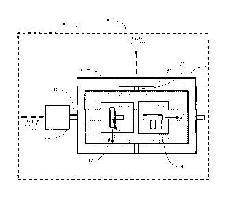
portion of the wellbore 20 using a gyroscopic sensor of the survey system 10
while the
-18-
CA 02691034 2010-01-25
gyroscopic sensor is in a first orientation relative to the wellbore 20 in an
operational block
170. In certain such embodiments, the method 100 further comprises generating
a sixth
signal indicative of the second component of the Earth's rotation
substantially perpendicular
to the portion of the wellbore 20 while the gyroscopic sensor is in a second
orientation
relative to the wellbore 20 in an operational block 180. In certain such
embodiments,
calculating information regarding at least one error contribution to
measurement signals from
the survey system 10 further comprises using the fifth signal and the sixth
signal. In certain
embodiments, the gyroscopic sensor used to generate the fifth signal and the
sixth signal is
the first gyroscopic sensor 12 (e.g., the first gyroscopic sensor comprises a
dual-axis gyro).
System Equations
[0049] The system equations used in certain embodiments to calculate
information regarding at least one error contribution to measurement signals
from the survey
system 10 are discussed below in conjunction with an example survey system 10.
This
example survey system 10 comprises a first gyroscopic sensor 12 comprising a
dual-axis
dynamically tuned gyro (e.g., xy-gyro) mounted to provide measurement signals
regarding
the components of the Earth's rotation along the lateral (x and y) axes of the
survey system
10. This example survey system 10 further comprises a second gyroscopic sensor
14
comprising a dual-axis dynamically tuned gyro (e.g., xz-gyro or yz-gyro)
mounted to provide
measurement signals regarding the components of the Earth's rotation along the
longitudinal
(z) axis of the survey system 10 and along a second axis that may be co-
incident with either
the x-axis or the y-axis, or an intermediate axis in the xy plane. In this
example survey
system 10, the indexing mechanism applies index rotations to both gyros about
their
respective spin axes.
[0050] During a stationary survey, the first gyroscopic sensor 12 and the
second
gyroscopic sensor 14 measure the components of Earth's rotation rate (a),
which may be
expressed in local geographic axes (defined by the directions of true north,
east and the local
vertical) as:
_ _ _
EICOSO
0 = 0 (1)
¨Chin 0
-19-
CA 02691034 2010-01-25
where OH and 0, represent the horizontal and vertical components of Earth's
rotation rate
respectively, and 0 is the latitude. The Earth's rotation rate may be
expressed in survey
system axes (x, y, z) as follows:
sin oe ¨ cos a 0 cos/ 0 ¨ sin /¨ cos A sin A 0 f2cos
= cosa sin a 0 0 1 0 ¨sin A cos A 0 0
0 0 1 sin/ 0 =cos/ 0 0 1 ¨Qsin0
- (2)
.S1c,osOcosAcos/sina +OsinOsin/sina + Ocos0sin Acosa-
= CI cos 0 cos AcosI cos a + S2sin 0 sin / cos a ¨ cos 0 sin A sin a
C1cos 0 cos A sin .1 ¨ sin 0 cosi
where A = azimuth angle, I = inclination angle, and a = high side tool face
angle as shown
in Figure 9.
[0051] The measurements of these quantities provided by the first and
second
gyroscopic sensors 12, 14 may be in error owing to a variety of causes,
including mounting
misalignments of the gyros, scale factor errors, and other imperfections
within the gyroscopic
sensors. These effects give rise to fixed and g-dependent bias terms in
dynamically tuned
gyros, including but not limited to, mass unbalance error and quadrature
error. While the
error terms can be identified and corrected following a pre-run calibration
procedure, some of
the errors are known to be unstable (e.g., biases and mass unbalance effects,
particularly for
rotor gyros), and the initial calibration therefore cannot be relied upon to
provide adequate
measurement accuracy throughout the operational use of the survey system 10.
100521 The equations for the individual gyro measurements and the
indexing
process are given below.
xy-gyro
[00531 The input axes of the xy-gyro of the first gyroscopic sensor 12
in this
example are nominally coincident with the x and y axes of the survey system 10
respectively,
and the spin axis of the xy-gyro is substantially parallel to the along-hole
direction (z axis).
The angular rotation rates applied about the sensitive axes of the xy-gyro may
be expressed
as:
cox = C2 H (COS A cos/ sin a + sin A cos a)¨ Qv sin /sin a
= c (cos A cos 1 cos a ¨ sin Asia a)¨ Qv sin / cos a (3)
-20-
CA 02691034 2010-01-25
In the presence of sensor bias instability, the xy-gyro measurements may be
expressed in
terms of the applied rates ( cox, ) and the measurement biases (B,,B,.) as
follows:
(4)
yo
= co + B
r r
The measurements will also include random bias terms, the effects of which may
be
substantially reduced by averaging a number of measurements sampled at high
speed. Such
effects are therefore ignored for the purposes of this example discussion.
100541 Upon being indexed by being rotated by 180 , the
gyro measurements
become:
(5)
yi r r
The fixed biases in the measurements may be determined by using the following
calculations:
Bx =((oxo+ cox312
=
6)
By= (coro +
and estimates of the input rotation rates (4, and 6, ) can be made by
calculating the
difference between the two index measurements for each input axis to remove
the effect of
measurement biases as follows:
= (cox ¨ cox, )/2 (7)
= (6)y0 (11)4 )/2
While this calculation removes residual biases from the measured rotation
rates, it does not
take account of measurement errors that may be present as a result of residual
mass
unbalance and quadrature errors. These effects are addressed separately below.
z- gyro
100551 For the purposes of this example, it is assumed
that one input axis Cu) of
the second gyroscopic sensor 14 is nominally coincident with the z-axis of the
survey system
10. The second input axis (v) and the spin axis (w) of the second gyroscopic
sensor 14 are
assumed to lie in the xy plane rotated through an angle 2 about the z-axis
with respect to the
x and y axes respectively, where A is defined as the gyro skew angle.
100561 The angular rates applied about the sensitive (u
and v) axes of the z-gyro
of the second gyroscopic sensor 14 may therefore be expressed as follows:
-21-
CA 02691034 2010-01-25
COu -Cü
(8)
roõ = coy os ¨ co x sin A.
or as a function of Earth's rate and survey tool orientation as:
coõ Du cos A sin / + 0, cos /
(9)
roõ = {cos A cos I cos(a ¨ sin A sin(a ¨ ,1.)} QV sin / cos(a ¨2)
Estimates of the z-gyro input rotation rates, denoted 6õ and cVõ can be formed
from the
measurements taken at indexed positions in a manner similar to that described
above for the
xy-gyro measurements.
= [00571 Having applied indexing corrections to the x, y, and u
(z) gyroscopic
measurements taken at each survey station, azimuth estimates can be generated
at each
station using the following equation:
(6., cos a ¨ 6y sin a)
tan A = _______________________________________________ (10)
Vox sin a + 6y cos a)cos + 6õ sin/
The inclination angle and tool face angle values used in equation (10) are
derived from
accelerometer measurements taken at each survey station.
[0058) In certain embodiments, the redundant rate measurement (2k,) from
the
second gyroscopic sensor 14 provides a check on the performance of the first
gyroscopic
sensor 12 (e.g., the xy-gyro), and can be used as an additional measure for
quality control
purposes. Redundant measurements can also be used directly in the azimuth
calculation (as
described below) in certain embodiments in which statistical calculation
methods such as a
least squares adjustment are used.
Mass unbalance and quadrature errors
100591 As described above, the xy-gyro measurements may be expressed in
terms
of the applied rates (w , CO,), measurement biases (Bx,By) using equation (4).
If the gyro
index angle is 0, the gyro measurements become:
coxi = co, cos + Oiy sin g +
(11)
¨ ¨co sine+ co cos0+ B
yi
Estimates of the input rotation rates (6, and 6,) can be made by first
calculating the
difference between the index measurements for each channel to remove the
effect of
-22-
CA 02691034 2010-01-25
measurement biases. Given knowledge of the index angle 9, the applied rotation
rates may
then be calculated using the following equations:
(cLixo 0,0 ) (
+ (y0 (i)y1 ) sin6'
=
2 2 (1 ¨ cos 0)
(12)
ACL)Y0 Cliy1 ) (WzCi ¨ ti ) sin
coy ¨
2 2 (l ¨ cos 0)
[0060] The indexing procedure described thus far may be extended to
facilitate
the estimation and correction of additional errors in the gyro measurements.
For example, in
certain embodiments, four index locations at 90 degree intervals may be
selected. In certain
such embodiments, the xy-gyro measurements may be expressed in terms of the
applied rates,
measurement biases (B1, B,), a mass unbalance offset (M) and a quadrature g-
dependent
bias (ary) as follows:
cox = cox + Bx+ M xy = a,+ Qvy = ay
(13)
coyo = coy+ By+111y=ay+Q,,y =
Indexed by 90 , the gyro measurements become:
(DA =." (1)), Bx +1111,y 'a y -a,
(14)
coy2 = ¨cox + By¨ M,y= ax+ Qxy=ay
Indexed by 180 , the gyro measurements become:
co = ¨C Ox Bx¨ M1, = ax ¨Q, = ay
(15)
coy, = ¨a)), + By¨ M = a y ¨Q. -ax
Indexed by 270 , the gyro measurements become:
cox3 = ¨COy Bx ¨ .11/11,-ay+ Qry = ax
(16)
Ca y3 = Cax +B, +M), M = a.,.¨Q,=ay
[0061] In certain embodiments, estimates of the biases (B1, ho can be
made by
calculating the sum of measurements taken at index positions that are 180
degrees apart, for
example:
13x=(c0,0+0).,,)/2
(17)
= (a)Y 0 +Y1V2
-23-
CA 02691034 2010-01-25
Following removal of the estimated biases from the measurements, estimates of
the
quadrature bias ( ) can be obtained in certain embodiments by calculating
the sum or
difference between measurements taken at index positions that are 90 degrees
apart, for
example:
= kr COy2V2ay
(18)
Similar calculations can be performed using the indexed z-gyro measurements in
order to
obtain estimates of the biases (Bu, BO and quadrature error (Q) associated
with the z-gyro.
[0062] In certain embodiments, estimates of the mass unbalance offset
for each
gyro of the first gyroscopic sensor ]2 and the second gyroscopic sensor 14 can
be determined
using the following procedure. Upon removal of the effects of biases and
quadrature errors,
the following measurement equations remain for a system containing two dual-
axis gyros
(e.g., two dynamically tuned gyros):
co
= + M - a
xo x x
= + M - a
ro r (19)
ono = a,,
= ax M = a,t
[0063] The measurement equations can be expressed in terms of Earth's
rotation
rate and the orientation of the survey system 10 (azimuth angle, inclination
angle, and tool
face angle):
a)A = (Cos A Cos / sin a + sin A cos a)¨ Q, sin / sin a ¨ Mµv sin /sin ce
(20)
cayo = (cos A cos / cos a ¨ sin A sin a)¨ Qv sin / cos a ¨ M sin / cos a
coo = S.2, cos A sin / + c,os / + cos/
= CLõ {cos A cos I cos(a ¨ A)¨ sin A sin(a ¨ C-2,, sin / cos(a ¨ .1.)+ M
sin / cos(a ¨
[0064] The survey system 10 will typically incorporate a triad of
accelerometers
in addition to the gyros of the first gyroscopic sensor 12 and the second
gyroscopic sensor 14.
The sensitive axes of these accelerometers in certain embodiments are
coincident with the x,
y and z axes of the survey system 10. In certain such embodiments,
measurements from the
accelerometers are used to determine the inclination angle ( 1 ) and the tool
face angle (a) of
-24-
CA 02691034 2010-01-25
the survey system 10 at each survey location or survey station within the
wellbore 20.
Further, in certain embodiments, the -uv-gyro mounting angle ( ) is known. In
certain such
embodiments, four equations remain with three unknowns; A, M,, and Mõ,. The
values of
these quantities can be determined in certain embodiments using a least
squares calculation
or other statistical filtering method.
[0065] Figures 10A and 10B are two flow diagrams of two example methods
200,
300 in accordance with certain embodiments described herein which
advantageously allow an
accurate directional survey to be obtained at any wellbore inclination using a
gyro survey
system 10 within a relatively short period of time. For example, in certain
embodiments, an
accurate directional survey is obtained within less than a minute. The time
for providing the
survey information is dependent on the time used to collect and average
measurements in
each index position, and the computing time is negligible. The duration of the
survey process
in certain embodiments is compatible with the exacting operational demands
placed upon
downhole survey systems.
[0066] In certain embodiments, a four-position index procedure is
performed for
each of the first gyroscopic sensor 12 and the second gyroscopic sensor 14
(e.g., the xy-gyro
and the z-gyro) in which measurements are taken at an initial orientation, and
at 90, 180 and
270 degree angles with respect to the initial orientation. These example
methods 200, 300
include implementing a set of calculations following the extraction of the
measurement data,
thereby allowing estimates of the gyro biases, mass unbalance, and quadrature
g-dependent
errors to be calculated. Thus, in certain embodiments, variations that may
well arise in the
magnitude of these gyro error terms between the calibration of a survey system
10 and its
subsequent operational use in the field may be removed, thus facilitating a
more accurate
gyro compassing survey than could otherwise be achieved.
[0067] In an operational block 210, the example method 200 shown in
Figure
10A comprises performing indexed rotations of the first gyroscopic sensor 12
and the second
gyroscopic sensor 14 and storing the measurement data obtained from each
gyroscopic sensor
and at each index position in memory_ In certain embodiments, the indexing
measurements
are taken at a number of pre-defined and accurately known angles (e.g., at an
initial
orientation defined to be zero degrees, at 90 degrees, at 180 degrees, and at
270 degrees). In
-25-
CA 02691034 2010-01-25
certain embodiments, both gyroscopic sensors (e.g., both the xy-gyro and the z-
gyro) are
indexed or rotated simultaneously, while in certain other embodiments, the
gyroscopic
sensors are indexed or rotated non-concurrently with one another.
[00681 In an
operational block 220, the sums of measurements taken with 180
degrees index separation are calculated for each gyroscopic sensor to
determine the residual
gyro biases for each gyroscopic sensor as described above. In an operational
block 230, the
sums and the differences of measurements taken with 90 degrees separation are
calculated for
each gyroscopic sensor to determine the residual quadrature errors for each
gyroscopic sensor
as described above. In an operational block 240, the residual gyro biases and
the residual
quadrature errors are used to correct measurements from the gyroscopic sensors
by
calculating corrected values for the measurements with these effects removed
or subtracted
out.
[0069) In an
operational block 250, a least-squares adjustment or statistical
filtering process is used to calculate the residual mass unbalance for each of
the first
gyroscopic sensor 12 and the second gyroscopic sensor 14. In certain such
embodiments,
' accelerometer measurements are pet __________________________________ formed
in an operational block 260 and these
measurements are used to calculate inclination and tool-face angle in an
operational block
270. The calculated inclination and tool-face angle can then be used in the
least-squares
adjustment or statistical filtering process to determine the system errors for
each gyroscopic
sensor and azimuth.
[00701 In an
operational block 310, the example method 300 shown in Figure 10B
comprises performing indexed rotations of the first gyroscopic sensor 12 and
the second
gyroscopic sensor 14 and storing the measurement data obtained from each
gyroscopic sensor
and at each index position in memory. In an operational block 320, a full
least-squares
adjustment or statistical filtering process is used to calculate all system
errors, including gyro
biases, mass unbalance, and quadrature errors via a single set of calculations
based on the
indexed measurements taken with each of the first gyroscopic sensor 12 and the
second
gyroscopic sensor 14. In certain such embodiments, accelerometer measurements
are
performed in an operational block 330 and these measurements are used to
calculate
= inclination and tool-face angle in an operational block 340. The
calculated inclination and
-26-
CA 02691034 2010-01-25
,
tool-face angle can then be used in the full least-squares adjustment or
statistical filtering
process to determine the system errors for each gyroscopic sensor and azimuth.
Statistical filter/estimation process
[0071] In certain
embodiments, a statistical filter for the calculation of the
residual bias, quadrature error, and/or mass unbalance contributions may be
constructed
based on a mathematical model of the system which yields estimates of the gyro
errors and
tool azimuth direction at each survey station. In the example embodiment
outlined below,
the filter is used to obtain estimates of any residual measurement biases and
the mass
unbalance offset associated with each gyroscopic sensor. In certain
embodiments, the states
of the system may be written as follows:
x = [ilk B,By Mxy BBi, MIno1T (21)
li
where 4 is the azimuth angle at survey station k; B, is the x axis measurement
bias of the
xy-gyro; B, is the y axis measurement bias of the xy-gyro; M,,, is the mass
unbalance for
the xy-gyro; Bõ is the u axis measurement bias of the z-gyro; By is the v axis
measurement
= bias of the z-gyro; and M, is the mass unbalance for the 2-gyro. 4 is a
station-dependent
state while the sensor errors are independent of tool location.
100721 The initial azimuth
(A0) may be determined using the initial set of indexed
gyro measurements via the following equations.
4 arcian , e.)k cos- 6 sine
[ Y
C'st) x sin e + 6, cos '?)cos ii
)cos i + ) sin i (22)
Gko - G1, õ Gy0 - Gyi . (Go - G"1) and GG G1,
where ct5õ = ________________ , oy =
.µ0, y 0 , x G,1 and
2 2 2
Go , Gõ1 are the respective xy and z-gyro measurements for the two indexed
measurement
positions, denoted by the subscripts 0 and I.
100731 Tool face angle and
inclination are computed using the accelerometer
measurements as follows:
_________________________________________________ _
e [ arctan -a ]
-ay = arctan . jazz + a
= 1 , 2
a , (23)
_
-27- ,
CA 02691034 2010-01-25
=
100741 The uncertainty in state estimates can be expressed in
certain embodiments
in terms of a covariance matrix at station k, denoted I. An initial value in
certain
embodiments is assigned to the diagonal elements of Pk , the variances of the
error estimates.
The azimuth variance of certain embodiments is set in accordance with the
expected accuracy
of the initial gyrocompass survey. In certain embodiments, initial values are
assigned to gyro
bias and mass unbalance variances in accordance with the expected variation in
these
parameter values following office calibration (e.g., calibration before the
system is placed
within the wellbore). The covariance matrix of the predicted state vector is
denoted by the
symbol Q.
[00751 Measurements of turn rate are provided by the gyro(s) at
consecutive
stationary survey locations. The gyro measurements obtained at survey station
k may be
expressed as:
= Fr0.k CAA Gy D,k y1,4 Gõo.k Go.k GõIski (24)
where dm is the i-axis measurement at index position j, for survey station k.
Gyro index
position 1 (j = 1) is displaced 1800 with respect to gyro index position 0 U=
0).
[0076) Estimates of the gyro measurements for survey station k
in certain
embodiments are written as:
zx0,k Gk GA./. Gyl.k G,,o.k G.1,4 Gy0.4 Gvl,k T (25)
where the individual measurement estimates may be expressed in terms of the
'states of the
model.
[0077) In certain embodiments, the differences between the gyro
measurements
and the estimates of these quantities, denoted Azk , form the inputs to a
Kalman filter, where
Azk 2.k ¨ zk
= [AGko.ktG11 AGyo., AGyi.k AGõ,,k AG, AGõ,,, AGjr (26)
The measurement differences may be expressed in terms of the system error
states,
Axk = [AAk AB, A B y ABõ AB, Aildõ, (27)
via the following linear matrix equation:
Azk = Hk Aak vk (28)
-28-
CA 02691034 2015-01-28
where Hk is a 8 x 7 matrix, in which the elements correspond to the partial
derivatives of the
theoretical measurement equations and vk represents the noise on the gyro
measurements.
The covariance of the measurement noise process at station k is denoted by the
symbol Rk.
[0078] The covariance matrix corresponding to the uncertainty in the predicted
state
vector in certain embodiments is given by:
PkIk-1= Pk-11k-1+Q (29)
where PkIk-1 is the covariance matrix at station k predicted at station k ¨1,
e.g., the
covariance matrix prior to the update using the inclination measurements at
station k. In
certain embodiments, the system states are corrected following each
measurement update,
so the best estimate of the state error following each measurement update is
zero.
Therefore, the predicted error state is also zero.
[0079] In certain embodiments, the covariance matrix and the state vector are
updated, following a measurement at station k, using the following equations:
Pklk = PkIk-l-Gk = Hk = PkIk-1 and Xklk = Xklk-1 Gk = A7k (30)
where Pkik is the covariance matrix following the measurement update at
station k Xklk_i is
the predicted state vector, and Xkik is the state vector following the
measurement update.
The gain matrix Gk is given by:
Gk = Pk1k-1= HkT[Hk = PkIk-1. H7; + Rkti (31)
[0080] In certain embodiments, estimates of additional gyro errors may be
included as
part of the gyrocompassing process described herein. Examples of the
additional gyro errors
which can be calculated in accordance with certain embodiments described
herein include,
but are not limited to, scale factor errors, mounting misalignments,
quadrature error, spin
axis sensitivity, and acceleration squared sensitivity.
[0081] Various embodiments have been described above. Although this invention
has
been described with reference to these specific embodiments, the descriptions
are intended
to be illustrative and are not intended to be limiting. Various modifications
and applications
may occur to those skilled in the art without departing from the scope of the
invention as
defined in the appended claims.
29