Language selection

Search

Patent 2691461 Summary

Third-party information liability

Some of the information on this Web page has been provided by external sources. The Government of Canada is not responsible for the accuracy, reliability or currency of the information supplied by external sources. Users wishing to rely upon this information should consult directly with the source of the information. Content provided by external sources is not subject to official languages, privacy and accessibility requirements.

Claims and Abstract availability

Any discrepancies in the text and image of the Claims and Abstract are due to differing posting times. Text of the Claims and Abstract are posted:

  • At the time the application is open to public inspection;
  • At the time of issue of the patent (grant).
(12) Patent: (11) CA 2691461
(54) English Title: TWO-STAGE HEAT EXCHANGER WITH INTERSTAGE BYPASS
(54) French Title: ECHANGEUR DE CHALEUR BI-ETAGE AVEC CONDUITE DE DERIVATION ENTRE ETAGES
Status: Deemed expired
Bibliographic Data
(51) International Patent Classification (IPC):
  • F04B 39/06 (2006.01)
  • F04B 39/02 (2006.01)
  • F28F 27/00 (2006.01)
(72) Inventors :
  • TYLISZ, BRIAN M. (United States of America)
  • MCDAVID, ANDREW (United States of America)
  • COUNTISS, ROBERT A. (United States of America)
(73) Owners :
  • SULLAIR CORPORATION (United States of America)
(71) Applicants :
  • SULLAIR CORPORATION (United States of America)
(74) Agent: NORTON ROSE FULBRIGHT CANADA LLP/S.E.N.C.R.L., S.R.L.
(74) Associate agent:
(45) Issued: 2014-09-16
(22) Filed Date: 2010-02-01
(41) Open to Public Inspection: 2010-08-13
Examination requested: 2010-02-01
Availability of licence: N/A
(25) Language of filing: English

Patent Cooperation Treaty (PCT): No

(30) Application Priority Data:
Application No. Country/Territory Date
12/370,632 United States of America 2009-02-13

Abstracts

English Abstract

A fluid cooler comprises a first stage fluid cooler and a downstream second stage fluid cooler. A flow line connects the first and second stages. A valve senses a condition of the fluid in the flow line, and to bypass the second stage fluid cooler if it is determined that additional cooling is not necessary. An air compressor incorporating the cooler is also claimed as is a method of operating a fluid cooler.


French Abstract

Refroidisseur de fluide comprenant un refroidisseur de fluide initial et un refroidisseur de fluide secondaire en aval. Une ligne d'écoulement relie les deux phases. Une vanne détecte la condition du fluide dans la ligne d'écoulement et entraîne le contournement du refroidisseur de fluide secondaire si une deuxième phase de refroidissement n'est pas nécessaire. L'invention concerne aussi un compresseur d'air dans lequel se trouve le refroidisseur, ainsi qu'une méthode d'exploitation d'un refroidisseur de fluide.

Claims

Note: Claims are shown in the official language in which they were submitted.

CLAIMS
1. A fluid cooler and compressor comprising:
a first stage fluid cooler and a downstream second stage fluid cooler, and a
flow line connecting said first and second stage fluid coolers;
a valve for sensing a condition of the fluid in said flow line, and to move to
a
position to bypass said second stage fluid cooler if it is determined that
additional
cooling is not necessary,
said valve sensing the temperature of a fluid;
a bypass line connected into said flow line, said bypass line communicating
with said
valve;
oil passed from a compressor through said fluid cooler;
said valve moving between a first position at which it allows all flow through

the flow line from the first stage fluid cooler to the second stage fluid
cooler, and to a
bypass position at which it does not allow any flow to the second stage fluid
cooler,
but allowing some flow to the second stage fluid cooler while moving between
these
two positions;
wherein said valve includes a temperature sensitive sensor; and
wherein said valve being positioned at an upstream end of said flow line.
2. The fluid cooler and compressor as set forth in claim 1, wherein said
temperature sensitive sensor expands to move the valve to block the bypass
when a
predetermined temperature is met.
3. The fluid cooler and compressor as set forth in claim 1, wherein there
is a
discharge manifold at a downstream end of said second stage fluid cooler, and
the
fluid is bypassed directly into the discharge manifold.
4. The fluid cooler and compressor as set forth in claim 3, wherein said
second
stage fluid cooler also has an inlet manifold, and flow channels are provided
between
said inlet manifold and said discharge manifold, and allow an included fluid
to be
cooled by air as it passes through said flow channels.

5. The fluid cooler and compressor as set forth in claim 1, wherein said
valve is
at an upstream end of the bypass line.
6. A compressor comprising:
a compressor having an oil inlet;
an oil supply line leading to a fluid cooler from said compressor, and a fluid
return
line leading from said fluid cooler and back to said compressor, said fluid
cooler
comprising a first stage fluid cooler and a downstream second stage fluid
cooler, and
a flow line connecting said first and second stage fluid coolers, a valve for
sensing a
condition of the fluid in said flow line, and to move to a position to bypass
said
second stage fluid cooler if it is determined that additional cooling is not
necessary;
said valve sensing the temperature of a fluid;
a bypass line connected into said flow line, said bypass line communicating
with said
valve;
said valve moving between a first position at which it allows all flow through

the flow line from the first stage fluid cooler to the second stage fluid
cooler, and to a
bypass position at which it does not allow any flow to the second stage fluid
cooler,
but allowing some flow to the second stage fluid cooler while moving between
these
two positions;
wherein once said valve has moved to a full bypass position, then no cooling
is done in the second cooler; and
wherein said valve includes a temperature sensitive sensor.
7. The compressor as set forth in claim 6, wherein there is a discharge
manifold
at a downstream end of said second stage fluid cooler, and the fluid is
bypassed
directly into the discharge manifold.
8. The compressor as set forth in claim 7, wherein said second stage fluid
cooler
also has an inlet manifold, and flow channels are provided between said inlet
6

manifold and said discharge manifold, and allow an included fluid to be cooled
by air
as it passes through said flow channels.
9. The compressor as set forth in claim 6, wherein said temperature
sensitive
sensor expands to move the valve to block the bypass when a predetermined
temperature is met.
10. The compressor as set forth in claim 6, wherein said valve is at an
upstream
end of the bypass line.
11. The compressor as set forth in claim 6, wherein said valve being
positioned at
an upstream end of said flow line.
12. The fluid cooler and compressor as set forth in claim 1, wherein once
said valve
has moved to a full bypass position, then no cooling is done in the second
cooler.
13. The compressor as set forth in claim 6, wherein said valve is full open
or full
closed, such that when the valve is delivering fluid into the bypass line, no
fluid from the
flow line communicates to the second stage fluid cooler.
14. The compressor as set forth in claim 6, wherein said valve moving
between a
first position at which it allows all flow through the flow line from the
first stage fluid
cooler to the second stage fluid cooler, and to a bypass position at which it
does not
allow any flow to the second stage fluid cooler, but allowing some flow to the
second
stage fluid cooler while moving between these two positions.
7

Description

Note: Descriptions are shown in the official language in which they were submitted.


CA 02691461 2010-02-01
TWO-STAGE HEAT EXCHANGER WITH INTERSTAGE BYPASS
BACKGROUND OF THE INVENTION
This application relates to a two-stage oil cooler, wherein an interstage
bypass directs oil around the second stage, when additional cooling is
unnecessary.
Compressors typically require oil, which can become hot during operation of
the compressor. Thus, oil is routed from the compressor through an oil cooler,
such
that the oil is periodically cooled and returned to the compressor. One
application
for a compressor is in an air compressor. Typically, the oil coolers are sized
to
handle high ambient temperature conditions, at which the oil will become quite
hot.
When the same oil cooler is used in lower ambient temperatures, the oil is not
as hot,
and there may be too mucli cooling capacity in the oil coolers.
Typical compressors may be provided with a valve that restricts the
compressor intake to reduce its capacity, which can also result in the oil
being cooler
than the preferred operating temperature.
Compressors can also be associated with the ability to vary the speed of the
compressor, thus reducing its capacity, which can also result in the oil being
cooler.
The thermal cycles associated with an oversize oil cooler can induce stress in

the core of the oil cooler, reducing its strength and its ability to withstand
internal
pressures.
It has been proposed to include a bypass valve into multi-stage heat
exchangers. However, the valve associated with this arrangement was at a
downstream end of a bypass line, and only served to reduce the amount of fluid

passing through the second stage heat exchanger.
SUMMARY OF THE INVENTION
A fluid cooler comprises a first stage fluid cooler and a downstream second
stage fluid cooler. A flow line connects the first and second stages. A valve
senses
a condition of the fluid in the flow line, and bypasses the second stage fluid
cooler if
it is determined that additional cooling is not necessary. An air compressor
incorporating the cooler is also claimed as is a method of operating a fluid
cooler.
1

CA 02691461 2010-02-01
These and other features of the present invention can be best understood
from the following specification and drawings, the following of which is a
brief
description.
BRIEF DESCRIPTION OF THE DRAWINGS
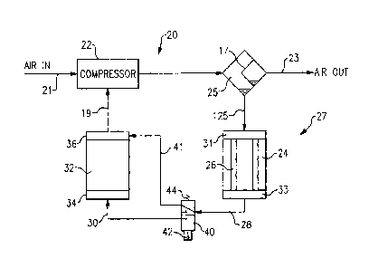
Figure 1 schematically shows a system incorporating the present invention.
Figure 2 shows the Figure 1 system in an alternative position.
DETAILED DESCRIPTION OF THE PREFERRED EMBODIMENT
System 20 includes a compressor 22 that receives air from line 21, and
compresses that air, delivering it towards a compressed air outlet 23. An oil
separator vessel 25 is positioned on the outlet of the compressor 22, and
includes a
separator element 17. The separator may be as known. Separated oil flows
through
line 125 towards an oil cooler 27. Downstream of the oil cooler 27, oil is
returned
through a line 19 back to compressor 22. While the present invention is
illustrated
in an air compressor, an oil cooler 27 of this invention may be incorporated
into use
with other compressors for other applications, and for other cooling
applications
beyond compressor oil coolers.
The oil cooler 27 has at least two stages, and incorporates a first stage 24
and
a downstream second stage 32. Oil from the compressor 22 passes into an inlet
manifold 31 in first stage 24, then passes through flow channels, shown here
schematically as tubes 26, to a discharge plenum 33. Air circulates around the

channels and cools the oil. From the discharge manifold 33, the oil flows into
a
connecting flow line 28 leading to a connection 30 to an inlet manifold 34 of
the
second stage 32 of the oil cooler. While not illustrated, the second stage 32
will also
include oil channels. It should be understood that the oil cooler stages 24
and 32,
and the flow channels, may be of any one of numerous configurations, and may
include fins, etc.
When inlet manifold 34 receives the oil from the line 30, it passes through
the cooler and to a discharge manifold 36, which then leads to a line
returning the oil
to the compressor 22. A bypass line 41 is connected to line 28.and includes a
valve
40. A spring 44 biases the valve to the position shown in Figure 1. In the
position
2

CA 02691461 2010-02-01
shown in Figure 1, the oil is bypassed around the second stage 32, and goes
directly
to the discharge manifold 36.
When the oil does not require additional cooling in second stage 32, the
valve 40 remains in the position shown in Figure 1, and the oil will bypass
the
second stage 32. All cooling will be done in the first stage 24, and the
concerns
mentioned above are avoided. A sensor 42 on the valve 40 monitors the
temperature
of the oil at line 28. If the oil temperature is above a threshold when
reaching valve
40, then sensor 42 will drive the valve to the position shown in Figure 2, at
which
position oil flows through the valve 40, and to line 30 leading to the second
stage oil
cooler 32.
As can be appreciated from the figures, the valves are either "full on" or
"full
off' and when in the Figure 1 position, will entirely bypass the second stage
oil
cooler 32. In the position of Figure 2, no fluid will flow through the bypass
line, and
it will be entirely blocked off. In addition, since the valve is at an
upstream end of
the bypass line, there will not be a dead volume of the fluid. The
specifically
disclosed valve will transition between the full on and full off positions,
and there
will be a state of transition where the fluid may be partially directed to
both
destinations. However, this will be a temporary condition, and the valve will
eventually arrive at the Figure 1 or the Figure 2 position.
In one embodiment, the sensor 42 may be a wax element that expands when
exposed to a predetermined temperature to drive the valve to the Figure 2
position.
On the other hand, other temperature sensitive elements may be utilized. In
addition, the valve 40 could be provided by an electronically controlled valve

wherein an electronic sensor senses temperatures and drives the valve to the
Figure 2
position when the predetermined temperature is met.
While the valve 40 and its associated components including sensor 42 and
spring 44 are shown schematically, a worker of ordinary skill in the art would

recognize how to provide a valve that can operate to achieve the disclosed
functions.
Moreover, other types of valves that operate in other manners would come
within
the scope of this invention. As an example, a valve may be normally biased to
the
Figure 2 position, and driven to the Figure 1 position, and would still come
within
the scope of this invention.
3

CA 02691461 2012-03-22
. .
In addition, while the figures show an oil cooler, this invention can be
incorporated into coolers for other fluids besides oil.
4

Representative Drawing
A single figure which represents the drawing illustrating the invention.
Administrative Status

For a clearer understanding of the status of the application/patent presented on this page, the site Disclaimer , as well as the definitions for Patent , Administrative Status , Maintenance Fee  and Payment History  should be consulted.

Administrative Status

Title Date
Forecasted Issue Date 2014-09-16
(22) Filed 2010-02-01
Examination Requested 2010-02-01
(41) Open to Public Inspection 2010-08-13
(45) Issued 2014-09-16
Deemed Expired 2017-02-01

Abandonment History

There is no abandonment history.

Payment History

Fee Type Anniversary Year Due Date Amount Paid Paid Date
Request for Examination $800.00 2010-02-01
Application Fee $400.00 2010-02-01
Maintenance Fee - Application - New Act 2 2012-02-01 $100.00 2012-01-05
Maintenance Fee - Application - New Act 3 2013-02-01 $100.00 2013-01-09
Maintenance Fee - Application - New Act 4 2014-02-03 $100.00 2014-01-07
Final Fee $300.00 2014-06-27
Maintenance Fee - Patent - New Act 5 2015-02-02 $200.00 2015-01-07
Owners on Record

Note: Records showing the ownership history in alphabetical order.

Current Owners on Record
SULLAIR CORPORATION
Past Owners on Record
COUNTISS, ROBERT A.
MCDAVID, ANDREW
TYLISZ, BRIAN M.
Past Owners that do not appear in the "Owners on Record" listing will appear in other documentation within the application.
Documents

To view selected files, please enter reCAPTCHA code :


To view images, click a link in the Document Description column. To download the documents, select one or more checkboxes in the first column and then click the "Download Selected in PDF format (Zip Archive)" or the "Download Selected as Single PDF" button.

List of published and non-published patent-specific documents on the CPD .

If you have any difficulty accessing content, you can call the Client Service Centre at 1-866-997-1936 or send them an e-mail at CIPO Client Service Centre.


Document
Description 
Date
(yyyy-mm-dd) 
Number of pages   Size of Image (KB) 
Abstract 2010-02-01 1 11
Claims 2010-02-01 3 69
Description 2010-02-01 4 153
Drawings 2010-02-01 1 15
Representative Drawing 2010-07-19 1 7
Cover Page 2010-08-05 1 34
Claims 2012-03-22 2 69
Description 2012-03-22 4 146
Claims 2013-01-22 3 118
Claims 2014-01-31 3 100
Representative Drawing 2014-09-02 1 6
Cover Page 2014-09-02 1 34
Assignment 2010-02-01 5 171
Prosecution-Amendment 2011-09-26 2 71
Prosecution-Amendment 2012-03-22 6 169
Prosecution-Amendment 2012-07-26 3 83
Prosecution-Amendment 2013-01-22 5 206
Prosecution-Amendment 2013-08-01 3 94
Prosecution-Amendment 2014-01-31 5 178
Correspondence 2014-06-27 2 67