Language selection

Search

Patent 2691551 Summary

Third-party information liability

Some of the information on this Web page has been provided by external sources. The Government of Canada is not responsible for the accuracy, reliability or currency of the information supplied by external sources. Users wishing to rely upon this information should consult directly with the source of the information. Content provided by external sources is not subject to official languages, privacy and accessibility requirements.

Claims and Abstract availability

Any discrepancies in the text and image of the Claims and Abstract are due to differing posting times. Text of the Claims and Abstract are posted:

  • At the time the application is open to public inspection;
  • At the time of issue of the patent (grant).
(12) Patent: (11) CA 2691551
(54) English Title: LENS DELIVERY SYSTEM
(54) French Title: SYSTEME DE PLACEMENT DE LENTILLE
Status: Deemed expired
Bibliographic Data
(51) International Patent Classification (IPC):
  • A61F 2/16 (2006.01)
(72) Inventors :
  • DOWNER, DAVID A. (United States of America)
  • YAN, DENGZHU (United States of America)
(73) Owners :
  • ALCON, INC. (Not Available)
(71) Applicants :
  • ALCON, INC. (Switzerland)
(74) Agent: KIRBY EADES GALE BAKER
(74) Associate agent:
(45) Issued: 2015-12-22
(86) PCT Filing Date: 2008-10-30
(87) Open to Public Inspection: 2009-05-07
Examination requested: 2013-10-07
Availability of licence: N/A
(25) Language of filing: English

Patent Cooperation Treaty (PCT): Yes
(86) PCT Filing Number: PCT/US2008/081679
(87) International Publication Number: WO2009/058929
(85) National Entry: 2009-12-21

(30) Application Priority Data:
Application No. Country/Territory Date
11/928,554 United States of America 2007-10-30

Abstracts

English Abstract


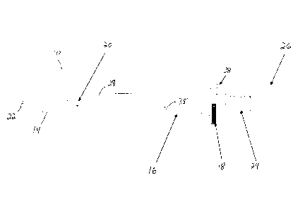
A lens delivery system handpiece having a threaded plunger rod with a ball
lock ring. Locking the ring causes the
plunger to be advanced by turning a thumbscrew or knob. Unlocking the ring
allows the plunger to be advanced by pushing on the
thumbscrew or knob in a manner similar to a syringe.


French Abstract

L'invention concerne une pièce à main de système de placement de lentille ayant une tige de plongeur filetée équipée d'une bague de retenue à bille. Le blocage de la bague amène le plongeur à avancer en tournant une vis de serrage à main ou une mollette. Le déblocage de la bague permet d'avancer le plongeur, de la même manière qu'une seringue, en poussant sur la vis de serrage à main ou la mollette.

Claims

Note: Claims are shown in the official language in which they were submitted.


Claims:
1. An intraocular lens delivery system, comprising:
a) a cartridge having a bore;
b) a handpiece, the handpiece having a notched portion for receiving the
cartridge;
c) a plunger coaxially received in the handpiece, the plunger having a distal
tip and a
proximal end opposite the distal tip, the tip reciprocating within the bore of
the cartridge
when the cartridge is received in the notched portion of the handpiece;
d) a grooved outer shaft received on the proximal end of the plunger, the
grooved
outer shaft having a knob rigidly attached thereon;
e) a ball lock ring rotationally mounted on the handpiece, the ball lock ring
having a
plurality of locking balls that ride within the groove of the outer shaft; and
0 a plurality of release angles in the ball lock ring corresponding to the
locking balls,
the release angles alternatively forcing the locking balls into and out of the
groove in the
outer shaft in response to rotation of the ball lock ring as the knob is
turned, wherein the
plunger is slidably advanceable to a distalmost injection position of slidable
advancement by
pushing the knob when the locking balls are out of the groove and the plunger
is threadedly
advanceable to the distalmost injection position of slidable advancement by
turning the knob
when the locking balls are in the groove allowing the intraocular lens to be
selectively
injected either by slidable or threaded advancement.
2. The lens delivery system of claim 1 wherein forcing the locking balls
out of the
groove in the outer shaft allows the plunger to be pushed within the
handpiece.
3. The lens delivery system of claim 1 wherein rotation of the grooved
outer shaft
causes the plunger to reciprocate within the handpiece.

Description

Note: Descriptions are shown in the official language in which they were submitted.


CA 02691551 2009-12-21
WO 2009/058929
PCT/US2008/081679
LENS DELIVERY SYSTEM
This invention relates to intraocular lenses (IOLs) and more particularly to
devices used to inject IOLs into an eye.
Background of the Invention
The human eye in its simplest terms functions to provide vision by
transmitting
and refracting light through a clear outer portion called the cornea, and
further focusing
ici the image by way of the lens onto the retina at the back of the eye.
The quality of the
focused image depends on many factors including the size, shape and length of
the eye,
and the shape and transparency of the cornea and lens.
When trauma, age or disease cause the lens to become less transparent, vision
deteriorates because of the diminished light which can be transmitted to the
retina. This
is deficiency in the lens of the eye is medically known as a cataract. The
treatment for this
condition is surgical removal of the lens and implantation of an artificial
lens or IOL.
While early IOLs were made from hard plastic, such as polymethylmethacrylate
(PMMA), soft, foldable IOLs made from silicone, soft acrylics and hydrogels
have
become increasingly popular because of the ability to fold or roll these soft
lenses and
20 insert them through a smaller incision. Several methods of rolling or
folding the lenses
are used. One popular method is an injector cartridge that folds the lenses
and provides a
relatively small diameter lumen through which the lens may be pushed into the
eye,
usually by a soft tip plunger. The most commonly used injector cartridge
design is
illustrated in U.S. Patent No. 4,681,102 (Bartell), and includes a split,
longitudinally
25 hinged cartridge. Similar designs are illustrated in U.S. Patent Nos.
5,494,484 and
5,499,987 (Feingold) and 5,616,148 and 5,620,450 (Eagles, et al.). In an
attempt to avoid
the claims of U.S. Patent No. 4,681,102, several solid cartridges have been
investigated,
see for example U.S. Patent No. 5,275,604 (Rheinish, et al.) and 5,653,715
(Reich, et al.).
The handpieces used with prior art cartridges generally push the lens through
the
30 cartridge using a plunger. The plunger is either pushed but the user
(similar to a syringe)
or is threaded and is advanced by turning a thumbwheel. Surgeon preference
generally
dictates which style handpiece is used but it is advantageous that a single
handpiece
contain a mechanism that allows both typed of movement.
1

CA 02691551 2009-12-21
WO 2009/058929
PCT/US2008/081679
Accordingly, a need continues to exist for a lens delivery system handpiece
having a plunger that can be advanced by pushing or by turning of a
thumbscrew.
2

CA 02691551 2009-12-21
WO 2009/058929
PCT/US2008/081679
Brief Summary of the Invention
The present invention improves upon prior art by providing a lens delivery
system
handpiece having a threaded plunger rod with a ball lock ring. Locking the
ring causes
the plunger to be advanced by turning a thumbscrew or knob. Unlocking the ring
allows
the plunger to be advanced by pushing on the thumbscrew or knob in a manner
similar to
a syringe.
It is accordingly an object of the present invention to provide a lens
delivery
system having a handpiece with a locking ring.
It is a further object of the present invention to provide a lens delivery
system
having a handpiece with a plunger that can be advanced by pushing or turning a
knob.
Other objectives, features and advantages of the present invention will become

apparent with reference to the drawings, and the following description of the
drawings
and claims.
Brief Description of the Drawings
FIG. 1 is a side elevational view of the handpiece of the lens delivery system
of
the present invention.
FIG. 2 is a cross-sectional view of the ball lock ring of the handpiece
illustrated in
FIG. 1 showing the lock ring in the locked position.
FIG. 3 is a cross-sectional view of the ball lock ring of the handpiece
illustrated in
FIG. 1 showing the lock ring in the unlocked position.
FIG. 4 is a perspective view of a cartridge that may be used with the lens
delivery
system of the present invention.
FIG. 5 is a cross-section view of the handpiece of the lens delivery system of
the
present invention.
Detailed Description of the Invention
As best seen in FIGS. 1 and 4, lens delivery system 10 of the present
invention
generally includes cartridge 12 and handpiece 14. Handpiece 14 generally
consists of
barrel 16, ball lock ring 18 (shown in FIG. 1 in partial cross-section) and
plunger rod 20.
3

CA 02691551 2015-03-17
As best seen in FIGS. 1 and 5, plunger rod 20 contains distal tip 22 and
proximal end 23
which is rotationally journaled into grooved outer shaft 24 so that outer
shaft 24 spins
freely on proximal end 23 of plunger rod 20. Rigidly attached to outer shaft
24 is knob
26. Pin 35 fits against flat portion 37 of plunger rod 20 so that rotation of
knob 26 and
outer shaft 24 does not cause plunger rod 20 to rotate, but that plunger rod
20 may freely
reciprocate within barrel 16. Barrel 16 contains notched portion 28 into which
cartridge
12 is received so that tip 22 of plunger rod 20 reciprocates within bore 30 of
cartridge 12.
As best seen in FIGS. 2 and 3, ball lock ring 18 contains a plurality of balls
34
sized to fit within groove 32 of outer shaft 24. Ring 18 also contains a
plurality release
io angles 36 opposite groove 32 corresponding to the location of balls 34.
As shown in
FIG. 2, rotating ball lock ring 18 counter-clockwise forces balls 34 into
groove 32 and
prevents plunger rod 20 from being advanced by pushing on knob 26. Instead,
turning of
knob 26 causes balls 34 to ride within groove 32 of grooved outer shaft 24,
thereby
threadedly pushing or pulling on proximal end 23 of plunger rod and causing
corresponding reciprocation of tip 22 of plunger rod 20 within bore 30 of
cartridge 12.
As best seen in FIG. 3, rotating ball lock ring 18 clockwise forces balls 34
out of groove
32 and allows plunger rod 20 to be advanced by pushing on knob 26. Index pin
38 and
slot 40 prevent over-rotation of ball lock ring 18.
While certain embodiments of the present invention have been described above,
these descriptions are given for purposes of illustration and explanation.
4

Representative Drawing
A single figure which represents the drawing illustrating the invention.
Administrative Status

For a clearer understanding of the status of the application/patent presented on this page, the site Disclaimer , as well as the definitions for Patent , Administrative Status , Maintenance Fee  and Payment History  should be consulted.

Administrative Status

Title Date
Forecasted Issue Date 2015-12-22
(86) PCT Filing Date 2008-10-30
(87) PCT Publication Date 2009-05-07
(85) National Entry 2009-12-21
Examination Requested 2013-10-07
(45) Issued 2015-12-22
Deemed Expired 2019-10-30

Abandonment History

There is no abandonment history.

Payment History

Fee Type Anniversary Year Due Date Amount Paid Paid Date
Application Fee $400.00 2009-10-21
Maintenance Fee - Application - New Act 2 2010-11-01 $100.00 2010-10-04
Maintenance Fee - Application - New Act 3 2011-10-31 $100.00 2011-10-04
Maintenance Fee - Application - New Act 4 2012-10-30 $100.00 2012-10-09
Request for Examination $800.00 2013-10-07
Maintenance Fee - Application - New Act 5 2013-10-30 $200.00 2013-10-09
Maintenance Fee - Application - New Act 6 2014-10-30 $200.00 2014-10-09
Final Fee $300.00 2015-07-06
Maintenance Fee - Application - New Act 7 2015-10-30 $200.00 2015-10-07
Maintenance Fee - Patent - New Act 8 2016-10-31 $200.00 2016-10-05
Maintenance Fee - Patent - New Act 9 2017-10-30 $200.00 2017-10-04
Owners on Record

Note: Records showing the ownership history in alphabetical order.

Current Owners on Record
ALCON, INC.
Past Owners on Record
DOWNER, DAVID A.
YAN, DENGZHU
Past Owners that do not appear in the "Owners on Record" listing will appear in other documentation within the application.
Documents

To view selected files, please enter reCAPTCHA code :


To view images, click a link in the Document Description column. To download the documents, select one or more checkboxes in the first column and then click the "Download Selected in PDF format (Zip Archive)" or the "Download Selected as Single PDF" button.

List of published and non-published patent-specific documents on the CPD .

If you have any difficulty accessing content, you can call the Client Service Centre at 1-866-997-1936 or send them an e-mail at CIPO Client Service Centre.


Document
Description 
Date
(yyyy-mm-dd) 
Number of pages   Size of Image (KB) 
Representative Drawing 2010-03-11 1 5
Cover Page 2010-03-11 1 30
Abstract 2009-12-21 1 51
Claims 2009-12-21 1 28
Drawings 2009-12-21 4 54
Description 2009-12-21 4 143
Description 2015-03-17 4 138
Claims 2015-03-17 1 39
Representative Drawing 2015-11-25 1 4
Cover Page 2015-11-25 1 29
PCT 2009-12-21 3 93
Assignment 2009-12-21 3 75
Correspondence 2010-01-11 2 41
Prosecution-Amendment 2015-03-17 4 134
Prosecution-Amendment 2013-10-07 1 41
Prosecution-Amendment 2014-10-16 4 256
Prosecution Correspondence 2015-10-07 7 846
Final Fee 2015-07-06 1 32
Correspondence 2015-10-15 1 3