Note: Descriptions are shown in the official language in which they were submitted.
CA 02691764 2009-12-23
WO 2009/002492 PCT/US2008/007842
Title
Image Guided Plaque Ablation
Field of the Invention
The invention relates to the field of treatment of atherosclerosis.
Particularly, the
invention relates to systems for reduction of vascular plaques.
Background of the Invention
Cardiovascular disease is a leading cause of morbidity and mortality
worldwide. It
occurs due to the formation of plaques within the coronary arteries over time,
leading to decreased blood flow to specific organs including brain and heart
muscle. Under certain circumstances, this decreased blood flow can cause
symptoms of transient ischemic attack, calf pain or angina. If the blockage of
the
arteries is more significant, it can lead to damage to the brain, legs or
heart
muscle itself and can be fatal.
One method of treatment of (cardio)vascular disease and avoidance of further
tissue damage is through invasive elimination of the plaque. This is typically
done
through invasive surgery. An alternative approach is through balloon
angioplasty,
which involve accessing the vessels using catheterization. Arterial stents may
also be placed during this procedure. When the nature of the plaque precludes
treatment by angioplasty, the plaques may be bypassed by grafting new vessels
around the areas of plaque during vascular or cardiac surgery procedure. In
some patients, neither angioplasty nor bypass surgery is possible, such as
when
the advanced age or poor health of the patient precludes such treatments or
when the plaque is not amenable to either therapy. In such cases, the patients
must attempt to control the disease through medical management such as
through the use of inedication. Because the surgical treatment of arterial
plaques
is invasive, the treatment is associated with the risk on complications, and
is not
suitable for all patients, a less invasive method for reducing or eliminating
plaque
formations in the arteries is therefore needed.
2
CA 02691764 2009-12-23
WO 2009/002492 PCT/US2008/007842
Non-invasive methods for treatment of unwanted material in tissues and
vessels,
typically cardiac vessels have been suggested for instance in US. Pat. Nos.
5,657,760, 5,590,657, and 5,524,620. However, these methods are not suitable
for the reduction of plaques, let alone in the vascular system.
Hence, there is a need for an accurate, reliable system for obviating and
reducing vascular plaques with a planned and controlled treatment therapy.
Summary of the Invention
This invention relates to a method and system for reducing vascular plaque.
For the purposes of this specification, the term 'cardiac rhythm' refers to
all or
any of the events related to the flow of blood that occur from the beginning
of one
heartbeat to the beginning of the next. Every single 'beat' of the heart
involves
three major stages: atrial systole, ventricular systole and complete cardiac
diastole.
According to this invention, there is provided a method for reducing vascular
plaques non-invasively comprises the following steps:
- imaging at least a portion of a mammalian body to produce an image;
- determining the location of at least one vascular plaque in said image;
- ascertaining the location of the base of said vascular plaque, said location
of base being the target location;
- precisely determining the relative position of said target location with
respect to the cardiac rhythm in the body;
- delivering a beam of ultrasound energy waves from a source to a focal
point in the relative position to elevate temperature of said target location
in a pre-determined manner;
- monitoring the temperature of the target location; and
3
CA 02691764 2009-12-23
WO 2009/002492 PCT/US2008/007842
- discontinuing delivery of ultrasound energy waves when said target
location achieves a pre-determined set temperature.
The method in accordance with this invention includes the step of displaying
said
image and said target location. It also includes the step of preparing a
therapeutic plan for treatment of said vascular plaque. The frequency of
ultrasound energy waves is adjusted to between 0.8 Hertz and about 4 Hertz.
The focal point of the beam of said ultrasound energy waves is, for instance,
less
than about 15 mm3. The intensity of focus of said ultrasound energy waves is
typically adjusted to greater than about 500 W/cm2. Further, the duration of
the
delivery of ultrasound energy waves is typically adjusted based on temperature
change. Typically, the time duration for delivery of ultrasound is adjusted to
between about 80 ms and about 1 second.
According to another aspect of this invention, there is provided a system for
reducing vascular plaque comprising:
- imaging device adapted to image at least a portion of a mammalian body;
- interpreting device adapted to interpret said image to locate at least one
vascular plaque and the base of said vascular plaque for determining
plaque location;
- monitoring device to monitor the relative position of said target location
with respect to the cardiac rhythm;
- at least one displaceable ultrasound delivery device adapted to deliver
ultrasound energy waves of a predetermined intensity to said target
location;
- temperature monitoring device to monitor temperature of said target
location; and
- device to shut-off delivery of ultrasound energy waves when the target
location achieves a predetermined set temperature.
4
CA 02691764 2009-12-23
WO 2009/002492 PCT/US2008/007842
The monitoring device is an ECG machine The ultrasound delivery device is a
High Frequency Ultrasound (HFU) device. The imaging device is a Magnetic
Resonance Imaging (MRI) device.
The imaging device and the interpreting device is capable of recognizing
plaque
in the vascular system of the imaged body and identifying the base of the
plaque
in the MRI images of the vessels. The HFU device is adapted to deliver HFU to
the base of the plaque identified by the imaging and interpreting device as
the
target location. The temperature monitoring device is capable of monitoring
the
temperature of the tissue at the target location via the thermal images to
determine when HFU delivery is complete.
The system in accordance with this invention may be used for treatment of
plaques within the carotid, iliac, femoral or coronary arteries. In accordance
with
an additional embodiment of this invention, an ECG monitoring device is
adapted
to monitor cardiac rhythm during said therapeutic treatment and process
signals
from said monitored ECG.
The controlling device controls the timing of MRI images and the delivery of
HFU
according to data received from the ECG monitoring device, so that HFU
delivery
and MRI images are triggered at a particular point in the cardiac cycle.
The controlling device is adapted to guide the ultrasound delivery device to
emit
ultrasound energy waves in confirmation with:
- specific angle or location of delivery;
- intensity of ultrasound energy waves to be emitted; and
- time duration for delivery of the ultrasound energy waves.
The aforementioned parameters depend upon the size and location of the plaque
as mapped by the imaging device.
The system includes a therapeutic treatment plan for determining the
parameters
CA 02691764 2009-12-23
WO 2009/002492 PCT/US2008/007842
of the delivered ultrasound energy waves. It may include a controlling device
to
receive said therapeutic treatment plan from an automated control unit and/or
by
manual intervention.
The delivery of HFU to the base of the plaque causes the temperature of the
tissue at the target location to rise. MRI monitoring of the target tissue
detects the
temperature increase. When the temperature increase is adequate, HFU
treatment is stopped. The HFU treatment may be repeated at the same target but
with an alternative angle of delivery. The HFU treatment may also be repeated
at
multiple target locations within the same plaques or within different plaques.
For each target, the HFU delivery is continued until an adequate amount of
treatment has been delivered to lead to scarring and plaque regression.
Brief Description of the Accompanying Drawings
The invention will now be described in relation to the accompanying drawings,
in
which:
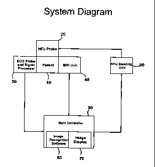
Figure 1 illustrates the system for non-invasive reduction of vascular
plaques;
and
Figure 2 illustrates the method of treatment for non-invasive reduction of
vascular
plaques.
Detailed Description of the Accompanying Drawings
Figure 1 illustrates the system for non-invasive reduction of vascular
plaques.
Treatment is delivered to the patient (10) using an ultrasound delivery
device,
typically through a High Frequency Ultrasound (HFU) emitting device (20).
During treatment delivery, the patient (10) is monitored by both an ECG
monitoring device (30) and a Magnetic Resonance Imaging (MRI) device (40).
Output from the ECG monitoring device (30) and the MRI device (40) are sent to
6
CA 02691764 2009-12-23
WO 2009/002492 PCT/US2008/007842
a interpreting a processing device (50) which includes image recognition
device
(60) and an image display device (70). The controller provides output to the
HFU
steering unit (80), which directs the delivery of energy by steering and
controlling
the HFU device (20).
During the procedure, the patient (10) is placed in a comfortable position on
a
treatment table where the patient must remain still. Because the procedure is
non-invasive, it may be performed without any sedation and without causing the
patient discomfort. The treatment table is located within the MRI device (40),
so
that the MRI images may be taken during the procedure to locate target lesions
and to monitor the progress of the treatment. The MRI device (40) must be
capable of providing images of the arteries which are sharply detailed so that
the
base of the plaque can be precisely identified, on the back side of the plaque
at
the vessel wall. An MRI device (40) which provides images with the capability
to
visualize tissue at a nanometer level of resolution, such as a 1.5, 3 or 7
Tesla
MRI unit, may be used in embodiments of the invention to provide these precise
images.
The patient (10) is also monitored by an ECG monitoring device (30) throughout
the duration of the procedure. The ECG monitoring unit (30) may be a standard
12-lead ECG or may be performed using fewer leads. Like all other components
used in or near the MRI device (40), the ECG monitoring device (30) must not
include any ferrous material. The beating of the patient's heart results in
motion
of the heart as well as of all arteries as they expand with each cardiac
contraction. The ECG is used to allow the system to compensate for this
motion.
In order to obtain useful MRI images, the taking of the MRI images is timed to
correspond to the beating of the patient's heart, such that each image is
taken at
the same point in the cardiac cycle. For example, the MRI device can be timed
to
take images during diastole, the relaxation phase of the heart. Likewise the
delivery of the HFU therapy is timed to the cardiac cycle using the ECG
monitoring device (30). After the target location is identified using an MRI
image,
7
CA 02691764 2009-12-23
WO 2009/002492 PCT/US2008/007842
HFU therapy is applied to the target location. In order to ensure correct
localization of the target location during treatment, the point during the
cardiac
cycle at which the MRI image is taken is the same as the point at which the
HFU
therapy is delivered. In this way, the target location identified using MRI is
the
same as the location to which the HFU therapy is delivered.
The ECG data is relayed to a processing device (50) throughout treatment. The
processing device (50) interprets the ECG data and provides instructions to
the
MRI device (40) and the HFU controller (80). The processing device (50) also
receives data from the MRI device (40) and includes image recognition device
(60) and an image display device (70). The image recognition device (60) may
be
used to identify plaque within the arteries by interpreting the signal in the
MRI
images. Alternatively, a clinician may visually identify plaque on the image
display (70) of the MRI images. In some embodiments, the image recognition
device (60) identifies the plaque and the clinician verifies the
identification using
the image display device (70). The image recognition device (60) and/or the
clinician identify the location at the base of each plaque which is the target
of the
HFU therapy.
After one or more target locations are identified by the processing device
(50)
and/or the clinician, a treatment plan is developed. A single plaque may
include
one target location or several target locations along the base of the plaque.
In
addition, an individual may have multiple plaques. In some cases, the
treatment
plan will include delivery of HFU to all identified plaque bases. In other
cases, it
may be desirable to selectively treat only some plaque bases or portions of
plaque bases and leave others untreated. Therefore the treatment plan includes
the decision regarding which plaque bases will be treated, and these locations
become the target locations. For each target location, the ideal alignment of
the
HFU device (20) with the patient (10) must also be determined. This will
depend
upon the location of the target location as well as factors such as individual
patient anatomy.
8
CA 02691764 2009-12-23
WO 2009/002492 PCT/US2008/007842
The following parameters depend upon the size and location of the plaque as
mapped by the MRI device (40):
- specific angle or location of delivery;
- intensity of ultrasound energy waves to be emitted; and
- time duration for delivery of the ultrasound energy waves.
In some cases, treatment may be delivered by a stationary HFU beam at a single
angle. Alternatively, it may be preferable to deliver HFU to a target location
using
a stationary HFU beam at more than one treatment angle. In some cases, HFU
may be delivered as the beam rotates through an arc of treatment angles. In
still
other cases, HFU may be delivered through multiple arcs of treatment angles.
This can be by means of a multilocus transducer. The method includes the step
of displacing the source of said beam. The displacement could be linear or
angular. By delivering treatment using more than one treatment angle, the
amount of energy delivered to tissue outside of the target location is
minimized
and therefore the risk of damage to other tissue may be decreased or
eliminated.
For each treatment angle and for each target location, a target temperature
must
be chosen. Therefore the treatment plan includes the details regarding which
target locations are to be treated, the angle at which the HFU will be
delivered,
whether multiple treatment angles will be used to deliver HFU to a target
location,
and what the final temperature of the target location will be for each HFU
delivery. The delivery of the ultrasound energy waves is either intermittent
or
pulsed, with the source of ultrasound delivery being displace after each pulse
or
after a series of pulses. The angle of delivery may be constant or changed
after
each pulse or a series of pulses. These determinations may be made by the
processing device (50) according to guidelines in its programming, by the
clinician, or by the clinician in combination with the processing device (50).
The delivery of HFU over an arc of treatment angles may be either rotational
or
stationary. When the treatment plan calls for the rotational delivery of HFU
over
an arc of angles, HFU treatment is delivered while the HFU device is actively
9
CA 02691764 2009-12-23
WO 2009/002492 PCT/US2008/007842
moving. However, the rotational delivery of HFU treatment of the arteries may
only be provided during a particular time window in each cardiac cycle, due to
motion of the arteries. Therefore, the arc of rotational treatment may be
formed
by a series of miniarcs, with treatment being delivered as the HFU device
rotates
through a series of miniarcs with each heart beat. For example, during a first
heart beat, treatment may begin at a first angle and rotate to a second angle,
forming a first miniarc. With the next heart beat, treatment may resume at the
second angle and rotate to a third angle, forming a second miniarc which is
consecutive with the first miniarc. Treatment would thus continue rotating
across
the miniarcs until the miniarcs together formed the planned treatment arc.
Alternatively, stationary treatment may be delivered over an arc of angles,
without rotating during HFU delivery. For example, during a first heart beat,
treatment may be delivered by a stationary HFU beam at a first angle. The HFU
device may be adjusted slightly, such as 1 millimeter, and during a second
heart
beat, treatment would be delivered by the stationary HFU device at a second
angle, which may be close to the first angle. The HFU device may continue to
adjust to consecutive treatment angles until treatment is delivered at series
of
angles to form an arc of treatment angles.
Alternative is one multilocus transducer adjusted in size and format to the
target
vessel or an arc with more than one transducer which delivers energy in a
consecutive manner.
The processing device sends instructions according to the treatment plan to
the
HFU controller (80), which controls the HFU delivery device (20). When the HFU
delivery device (20) is inside the MRI device (40), it must not include any
ferrous
material. During treatment, the treatment face of the HFU delivery device (20)
is
in contact with the surface of the patient (10) directly or through an
intermediate
substance such as a gel patch, on the patient's neck, groin or chest, for
example.
When a gel patch is used, is able to compress to correct for the distance
between the patient's surface and the target location in the vessel. The use
of a
gel patch may therefore be appropriate for treatment plans which call for the
CA 02691764 2009-12-23
WO 2009/002492 PCT/US2008/007842
rotational delivery of HFU therapy over a treatment arc, so that the distance
between the HFU device and the target location remains constant while the HFU
device rotates around the target location. The ultrasound delivery device (20)
is
mobile and can be precisely positioned and angled relative the patient (10) in
order to direct HFU precisely to the target location. The maximum distance
between the ultrasound delivery device (20) and the target location is
preferably
less than. about 6 cm. This maximum distance may be taken into account when
developing the treatment plan.
The HFU emitting ultrasound delivery device (20) delivers ultrasonic waves to
the
target location at the base of the plaque, causing the target location to
increase
in temperature. The size of the HFU focal point is preferably less than about
15
mm3. This may be achieved using HFU waves at a frequency of between about
0.8 and about 4 Hertz and with an intensity of the focus of between about 500
and about 3000 W/cm2. The HFU delivery device (20) delivers HFU to the target
location in repeated brief intervals which are correlated to a specific point
in the
cardiac cycle as detected by the ECG, according to instructions from the
processing device (50). The duration of each HFU delivery may be from
approximately 80 milliseconds to approximately 1 second. The appropriate
duration of each HFU delivery depends upon the individual patient's heart
rate.
The duration of each HFU delivery could be a short duration appropriate for
most
or all patients, regardless of the patient's heart rate. Alternatively, the
duration of
each HFU delivery could determined for each individual patient depending upon
the measured heart rate. Finally, the duration of each HFU delivery could vary
during each individual patient's treatment in response to measured heart rate.
The HFU delivery device (20) continues delivering HFU to the target location
until
the tissue reaches the desired temperature according to the treatment plan. In
some embodiments, the maximum desired temperature of the target location is
approximately 80 degrees Celsius. The temperature of the target location is
determined by the processing device (50) based on images provided by the MRI
11
CA 02691764 2009-12-23
WO 2009/002492 PCT/US2008/007842
device (40). In order to monitor the temperature increase, the system may
periodically take MRI images during the treatment process. For example, the
system may take an MRI image after each delivery of HFU treatment.
Altematively, MRI images may be taken during delivery of HFU treatment. For
example, an MRI image may be taken during initial treatment, then repeated
after
several HFU pulses. The MRI images may then be repeated during the treatment
to monitor the progress. The signal of the MRI image at the target location
changes in a manner which corresponds to the temperature of the tissue. The
processing device (50) includes device which can interpret the changes in the
MRI image of the target location to determine the temperature of the tissue.
When the desired temperature is reached, the processing device (50) instructs
the HFU controller (80) to discontinue the delivery of HFU.
Figure 2 presents a method of treatment according to embodiments of the
invention. The treatment begins at the start, step 100. At step 102, MRI
images
are taken of the coronary vessels. The MRI images are used to identify plaque
and target locations at the base of the plaque at step 104. Based on the MRI
images, a treatment plan is developed at step 106 by the processing device
and/or the clinician. HFU therapy is then applied to the precise location in
the
vessel wall at step 108 through either a stationary beam or a rotational beam.
MRI imaging of the target location is performed at step 110. The MRI image is
processed to determine whether the desired temperature has been achieved
according to the treatment plan at step 112. If the desired temperature has
not
been achieved, the steps of HFU therapy 108, MRI imaging 110 and MRI image
processing 112 are repeated until the desired temperature is achieved.
A determination of whether the treatment plan calls for further treatment
angles
or arcs of treatment angles to the target location is made at step 114. If a
further
treatment angle or arc of angles are planned, the starting location and
beginning
angle of the HFU emitting device are adjusted at step 116 and HFU therapy is
applied again at step 108 to the same target location at a new angle. MRI
12
CA 02691764 2009-12-23
WO 2009/002492 PCT/US2008/007842
imaging and image processing are repeated at steps 110 and 112 until the
desired temperature is achieved using the new HFU device angle.
When no further treatment angles are planned for a target location, a
determination is made regarding whether further treatment is planned for
another
target location at step 118. If no treatment is planned for other target
locations,
then the treatment is at an end at step 122. However, if further treatment
locations are planned, then the location of the HFU device is adjusted at step
120
to deliver HFU to a new target location, and the process is repeated for the
new
treatment location. This is repeated until all planed target locations have
been
treated.
By applying HFU to the base of the plaque, the targeted tissue in the vessel
wall
experiences an increase in temperature. This temperature increase leads to
inflammation of the tissue and later to scar formation which is sufficient to
reduce
or destroy the vaso vasorum, which is the vascular supply to the base of the
plaque. It is believed that the loss of vascularization to the vessel wall at
the base
of the plaque will lead to the eventual regression of the plaque. Because the
HFU
is very precise, it can deliver energy to the base of the plaque without
damaging
the vessel wall. In this way, HFU therapy can be used to non-invasively reduce
or
eliminate plaque.
Embodiments of the invention non-invasively treat atherosclerotic disease
using
targeted ultrasound therapy, thus avoiding the risks inherent to invasive
interventions. In addition, by avoiding surgery, the treatment process is
easier for
the patient and the clinician, can be performed more rapidly and involves less
patient discomfort and a quicker and easier recovery. Furthermore, it offers a
therapy option for patients who did not qualify for surgical intervention.
While
some embodiments of the invention are appropriate for use in the large
arteries,
the treatment may also be performed to reduce atherosclerosis in other
locations
in the body including the coronary arteries.
13
CA 02691764 2009-12-23
WO 2009/002492 PCT/US2008/007842
The image guided cardiac ablation method and system can potentially be used in
the following vascular applications:
- for eliminating atherosclerosis which includes removal of atherosclerotic
plaques typically in a. femoralis, in a. carotis, in a. renalis, or in a
coronary artery.
It can also be used for eliminating thrombolysis which includes intracranial
thrombosis, thrombosis in hemodialysis shunts, thrombosis in left atrial
appendage (LAA), venous thrombosis, and pulmonary embolism. It can further
be used for eliminating occlusion of vessels typically in medical conditions
such
as hemorrhage, sealing of punctures, varicosis, pseudoaneurysmata, vascular
malformations in the brain, and in bloodless resection of organs, bleeding
esophageal varices, and also to separate twins sharing a single placenta.
The image guided cardiac ablation method and system can potentially be
extended for use in the following non-vascular applications:
- in cases relating to malignancy including prostate carcinoma, breast
carcinoma,
hepatocellular carcinoma, renal cell carcinoma, urinary bladder carcinoma,
pancreas cancer, and osteosarcoma. It can also be used in other non-vascular
application not relating to malignancy such as benign prostate hypertrophy,
uterus fibroids, fibroadenoma (breast, liver).
Still further, the image guided cardiac ablation method and system can be used
for treatment of glaucoma, pain treatment, treatment of functional disorders
of the
brain (epilepsy, Parkinson's disease), lithotrypsy (urinary, bile), vasectomy,
synovectomy (in rheumatoid arthritis), cutaneous lesion recovery (vaivular
dystrophy, lymphatic drainage, skin care) and also in cases relating to atrial
fibrillation (MAZE procedure).
It can also be used in Gene targeting and drug delivery applications.
14
CA 02691764 2009-12-23
WO 2009/002492 PCT/US2008/007842
While considerable emphasis has been placed herein on the specific elements of
the preferred embodiment, it will be appreciated that many alterations can be
made and that many modifications can be made in the preferred embodiment
without departing from the principles of the invention. These and other
changes
in the preferred embodiment as well as other embodiments of the invention will
be apparent to those skilled in the art from the disclosure herein, whereby it
is to
be distinctly understood that the foregoing descriptive matter is to be
interpreted
merely as illustrative of the invention and not as a limitation.