Note: Descriptions are shown in the official language in which they were submitted.
CA 02691858 2015-03-09
WO 2009/015464 PCT/CA2008/001365
HEAT SEALING JAW, APPARATUS AND METHOD
[0001] This application claims the benefit of U.S. provisional
application no. 60/962,517,
filed July 30, 2007.
FIELD OF THE INVENTION
[0002] This invention relates generally to the production of
packaging pouches and more
specifically to a heat sealing jaw that is suitable for producing an easy-open
feature on a packaging
pouch.
SUMMARY OF THE INVENTION
[0003] Packaging pouches are typically made on form, till and seal
machines. For example,
using a vertical form, fill and seal machine, a flat web of synthetic
thermoplastic film is unwound
from a roll and formed into a continuous tube in a tube forming operation, by
sealing the
longitudinal edges of the film together to form a lap seal or a fin seal. The
tube thus formed is
pulled vertically downwards to a filling station. The tube is then collapsed
across a transverse
cross-section of the tube, the position of the cross-section being at a
sealing device below the filling
station. A transverse heat seal is made by the sealing device at the collapsed
portion of the tube,
thus making an airtight seal across the tube. The sealing device generally
comprises a pair of jaws.
[0004] After making the transverse seal, but before the jaws of the
sealing device are
opened, a quantity of material to be packaged, for example a liquid, is caused
to enter the tube at the
filling station, and to fill the tube upwardly from the aforementioned
transverse seal. The tube is
then caused to move downwardly a predetermined distance. This movement may be
under the
influence of the weight of the material in the tube, or it may be caused by
pulling or mechanically
driving the tube The jaws of the sealing device are closed again, thus
collapsing the tube at a
second transverse section. The second transverse section may be above, usually
just above the
air/material interface in the tube, or the second transverse section may be
below the air/material
interface. The sealing device seals and severs the tube transversely at the
second transverse section.
The material filled portion of the tube is now in the form of a pillow shaped
pouch. Thus the
sealing device has sealed the top of the filled pouch and sealed the bottom of
the next pouch to be
formed, all in one operation. The filling of the product may be conducted on a
continuous or
intermittent basis. One such vertical form, fill and seal machine of the type
described above is sold
- 1 -
CA 02691858 2010-01-12
WO 2009/015464
PCT/CA2008/001365
under the trade-mark PREPAC. Other suitable machines are sold under the trade-
marks INPACO
and ELECSTER.
[0005] A variety of flowable materials may be packaged in this
manner, for example, milk,
syrups, sauces, juices, water and the like. The term "flowable material" can
include materials that
are flowable under gravity or may be pumped. Such materials may include
emulsions, pastes,
peanut butter, preserves, dough, ground meat, powders, detergents, oils and
granular solids. Such
pouches can also be used to contain other flowable materials such as foods
that are packaged under
sterile, pasteurized or aseptic conditions. The packaging conditions will
normally require
modifications to the machine and also modifications to the methods of
packaging.
[0006] The pouches produced through this type of process can be
manufactured to contain
any volume of flowable material. In the situation where drinking fluids are
packaged in this
fashion, a typical size might be 250 mls or 500 mls. In such instance, it is
possible to consume the
fluid directly from the pouch. Thus, providing a pouch that includes an easy-
open feature for this
purpose is desirable especially when served in correctional facilities since
it avoids the necessity to
use an implement such as a knife or scissors. In addition, since these
packages are meant for one-
time use and are disposable, it is appropriate that the manner in which they
are manufactured is as
economical as possible, without sacrificing the basic packaging requirements
for the materials in
question.
[0007] Many solutions have been proposed for producing packages of
this type, and
typically such packages have included a notch or tear line which allows the
package to be opened.
For example, French Patent No. 1 216 422 discloses liquid-filled polymer
pouches that are
produced by collapsing a tube and having an easy-open feature. The easy-open
feature comprises a
sealed area partially extending across the width of the pouch and a weakened
line extending within
the sealed area. The weakened line is formed using a set of jaws where one jaw
comprises a piano
wire.
[0008] United Kingdom Patent No. 898,641 discloses a pouch having a
line of weakness for
easy opening that is produced by pressing the sheet between a solid plate and
a ribbed die while
heat is applied. The sheet is pinched between the plate and the rib of the die
and reduced in
thickness but not sheared, or otherwise punctured along the desired line.
[0009] U.S. Patent No. 5,038,550 and European Patent No. 0 372 886 both
disclose pouches
having a slit formed within a sealed portion. The slit is intended as a device
for starting a tear and
- 2 -
CA 02691858 2010-01-12
WO 2009/015464
PCT/CA2008/001365
for directing the tear in a preferred direction. In both cases the sealed
portion is formed first using a
sealing element and then the slit is formed using a separate cutting operation
using a knife.
[0010] U.S. Patent Application Publication No. US 2006/0110081 Al
published on May 25,
2006, discloses a pouch for containing a flowable material, provided with an
easy-open feature
located adjacent to an upper closure or a lower closure of the pouch. The easy-
open feature
comprises a seal formed between two layers of film and provides a tear line
for opening the pouch
and tearing a corner off the pouch.
[0011] One concern with easy-open features in packaging pouches is
that during the
production, filling, handling or any manipulation of the pouches, stresses are
induced in the film
that forms the walls of the pouch. Therefore, depending on the configuration
of the easy-open
feature, it may produce a stress concentration in the film and hence make the
film more susceptible
to tearing in specific areas.
[0012] Thus there is a need for an improved heat sealing jaw that can
be used to easily and
economically produce an easy-open feature in a pouch that is sufficiently
robust to withstand
stresses induced on the pouch during manipulation and/or filling of the pouch.
[0013] Accordingly, the present invention provides a heat sealing jaw
which can be used to
produce a packaging pouch with an easy-open feature, wherein the easy-open
feature does not
significantly compromise the integrity of the packaging pouch.
[0014] According to one aspect, the present invention provides a heat
sealing jaw for use in
cooperation with an opposing backing jaw for sealing layers of film together
to form a sealed
portion and a notch within the sealed portion. The heat sealing jaw comprises
a jaw body, a heat
sealing element secured to the jaw body, a support surface associated with the
heat sealing element
for clamping the layers of film against the opposing backing jaw and a heat
sink coupled to the heat
sealing element. The heat sealing element has a sealing face for pressing the
layers of film together
against the opposing backing jaw and forming the sealed portion. The sealing
face has a protrusion
for forming the notch within the sealed portion. The heat sink is coupled to
the heat sealing
element at a location adjacent to the support surface, and during operation,
the heat sink induces a
temperature gradient along the sealing face of the heat sealing element.
[0015] Advantageously, the heat sealing element may further comprise
a clamping portion
that is disposed at an orientation diverging from a plane along which the
layers of film are sealed
-3 -
CA 02691858 2010-01-12
WO 2009/015464
PCT/CA2008/001365
together. This tends to facilitate the securing of the heat sealing element to
the jaw body which may
also serve as the heat sink.
[0016] According to another aspect, the present invention also
provides a heat sealing jaw
for use in cooperation with an opposing backing jaw for forming an easy open
feature adjacent to an
edge of a packaging pouch made from layers of film sealed together. The heat
sealing jaw
comprises a jaw body, a heat sealing element secured to the jaw body, a
support surface associated
with the heat sealing element and a heat sink coupled to the heat sealing
element. The heat sealing
element has a sealing face for forming a sealed portion extending inwardly
from the edge of the
pouch. Accordingly, the sealing face has an outboard end to be positioned
outside of the edge of
the pouch, an inboard end to be positioned inside the edge of the pouch and a
protrusion for forming
the notch within the sealed portion. The support surface is associated with
the inboard end of the
sealing face for clamping the layers of film against the opposing backing jaw.
The heat sink is
coupled to the heat sealing element at a location adjacent to the inboard end
of the sealing face, and
during operation, the heat sink induces a temperature gradient along the
sealing face of the heat
sealing element.
[0017] According to another aspect, the present invention provides a
heat sealing element
for use in a heat sealing jaw in cooperation with an opposing backing jaw for
sealing layers of film
together to form a sealed portion and a notch within the sealed portion. The
heat sealing element
comprises a sealing face for pressing the layers of film together against the
opposing backing jaw
and forming the sealed portion, and, a clamping portion adjacent to the
sealing face. The sealing
face has a protrusion for forming the notch within the sealed portion. The
clamping portion is
disposed at an orientation diverging from a plane along which the layers of
film are sealed together.
[0018] According to a further aspect, the present invention provides
a method of sealing
layers of film together to form a sealed portion and a notch within the sealed
portion comprising the
steps of:
a) providing layers of film to be sealed together between a
heat sealing jaw and
a cooperating backing jaw, the heat sealing jaw comprising a heat sealing
element
with a sealing face having a length and a protrusion extending partly along
the length
of the sealing face;
b) inducing a temperature gradient along the length of the sealing face of
the
heat sealing element, wherein a first temperature of the sealing face adjacent
to the
- 4 -
CA 02691858 2010-01-12
WO 2009/015464
PCT/CA2008/001365
protrusion is higher than a second temperature of the sealing face at a
distance from
the protrusion;
c) closing the jaws to press the layers of film between the sealing face of
the
heat sealing element and the backing jaw, and, to simultaneously clamp the
film at a
location adjacent to the sealing face;
d) holding the jaws closed for a period of time required to form the sealed
portion and the notch; and
e) opening the jaws to release the layers of film.
[0019] The above method may be performed on a pouch forming and
filling machine such
as a vertical form, fill and seal packaging machine, in conjunction with
additional steps that are
required to form a packaging pouch having an easy-open feature and filled with
flowable material.
Accordingly, the layers of film may be provided between the heat sealing jaw
and the cooperating
backing jaw in the form of a film tube that is partially filled with flowable
material. The
temperature gradient along the length of the sealing face may be induced by
extracting heat from
the heat sealing element using, for example, a heat sink coupled to the heat
sealing element.
BRIEF DESCRIPTION OF THE DRAWINGS
[0020] Further details of these and other aspects of the present
invention will be apparent
from the detailed description and figures included below, which are exemplary
and included for =
illustrative purposes. Those skilled in the relevant art(s) will understand
that the following
description and drawings and are not intended to limit the scope of the
teachings herein in any way.
[0021] Reference is now made to the accompanying figures, in which
like references are
intended to refer to like or corresponding parts:
Figure 1 is an isometric view of a heat sealing jaw according to an embodiment
of
the present invention;
Figure 2 is an isometric view of the heat sealing jaw of Figure 1 with a clamp
removed;
Figure 3 is an isometric view of a heat sealing element from the heat sealing
jaw of
Figure 1;
Figure 4 is a cross-sectional view of the heat sealing element of Figure 3
along line
4-4 in Figure 3;
- 5 -
CA 02691858 2015-03-09
WO 2009/015464
PCT/CA2008/001365
=
Figure 5 is a front elevation view of a packaging pouch having an easy-open
feature
formed using the heat sealing jaw of Figure 1;
Figure 6 is an isometric view of the heat sealing jaw of Figure I positioned
in
relation to an opposing resilient backing member;
Figure 7 is a front elevation view of the heat sealing jaw of Figure 1
positioned in
relation to a film tube used for producing the pouch of Figure 5; and
Figure 8 is an isometric view of the heat sealing jaw of Figure 1 positioned
within
the filling compartment of a vertical form, fill and seal packaging machine.
DETAILED DESCRIPTION OF THE PREFERRED EMBODIMENTS
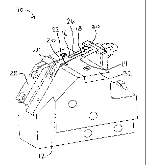
[0022] Referring now to Fig. 1, a heat sealing jaw, generally shown at 10,
for use in
cooperation with an opposing backing jaw (not shown) for sealing layers of
film together is shown.
The heat sealing jaw 10 can be used on a vertical form, fill and seal (VFFS)
packaging machine for
producing an easy-open feature on a pouch containing flowable material.
[0023] Many types of films can be used to manufacture pouches in
accordance with the
present invention. Generally these films must be capable of self-sealing and
processing through the
VFFS equipment. They should be stiff enough and strong enough for the proposed
packaging
applications. The nature of the packaging application determines the film
selection and the person
skilled in the art would be capable of readily selecting a suitable film for
the desired purpose.
Examples of suitable films include any synthetic thermoplastic polymeric film
which meets the
above-mentioned criteria. The films may contain a barrier layer selected from
nylon polymers,
polyethylene terephthalate polymers, amorphous nylon or ethylene vinyl
alcohol. An additional tie
layer may be present and can be selected from ethylene vinyl acetate polymer,
ethylene acid
copolymers, ionomers or anhydride functionalized ethylene copolymers. All of
these may be
combined with at least one high pressure ethylene homopolymer. Other examples
of suitable films
are described in the following references: WO 98/34844, WO 98/29249, WO
97/20693,
WO 97/12755, WO 95/21743, WO 95/10566, WO 95/00587.
These are merely representative examples of thermoplastic films
and the invention is not to be limited in any way with respect to the film
selected for manufacture of
the pouch.
[0024] As shown in Figs. 1-4, the heat sealing jaw 10 comprises a jaw body
12 and a heat
sealing element generally shown at 14 secured to the jaw body 12. The heat
sealing element 14
comprises a sealing face 16 having a first end 18 and a second end 20, and, a
back face 22. The
- 6 -
CA 02691858 2015-12-21
WO 2009/015464 PCT/CA2008/001365
heat sealing element 14 also has a clamping portion 24 that is disposed at an
orientation diverging
from the sealing face 16, which is also diverging from a plane along which the
layers of film are
sealed together during operation. The sealing face 16 has a rib-shaped
protrusion 26 which is
located at a distance from the second end 20.
[0025] The heat sealing element 14 is secured to the jaw body 12 by
clamping the clamping
portion 24 of the heat sealing element 14 to the jaw body 12 using a clamp 28.
The clamping
portion 24 of the heat sealing element 14 is thermally and electrically
connected to the jaw body 12
so that the jaw body 12 can also serve as an electrical terminal of the heat
sealing element 14. The
heat sealing element 14 is also electrically connected to terminal 30 which is
electrically isolated
from the jaw body 12.
[0026] A thermal insulator 32 is also disposed on at least a portion
of the back face 22 of the
heat sealing element 14 so as to thermally insulate the heat sealing element
14 from the jaw body 12
in a region adjacent to the sealing face 16.
[0027] Referring now to Fig. 5, an exemplary packaging pouch generally
shown at 34 and
made in accordance with the present invention is shown. The pouch 34 is made
by sealing layers of
film together and comprises an upper transverse seal 36, a lower transverse
seal 38 and a
longitudinal fin seal 40. The pouch 34 also has an easy-open feature 42,
disposed along or adjacent
to a side edge 44 of the pouch 34. The easy-open feature 42 can be made using
the heat sealing jaw
10 and comprises a sealed portion 46 and a notch 48 within the sealed portion
46.
[0028] In order to seal the layers of film together and produce the easy-
open feature 42 on
the pouch 34, the heat sealing jaw 10 works in cooperation with an opposing
conventional backing
jaw which is not shown. However, a resilient backing member 50 which is part
of the opposing
backing jaw is shown in Fig. 6. The structure and configuration of such
backing jaws are known to
one skilled in the art. The heat sealing element 14 is heated by resistance
heating and the layers of
film are pressed together between the heat sealing jaw 10 and the resilient
backing member 50.
[0029] The protrusion 26 on the sealing face 16 forms the notch 48
within the sealed portion
46 of the easy-open feature 42. The geometry of the protrusion 26 may be
selected based on the
notch geometry desired. The notch 48 may comprise an indentation, a cut or any
type of material
weakness formed within the sealed portion 46 that can be used to initiate
tearing of the layers of
film and thereby facilitate the opening of the pouch 34. For example, the
protrusion 26 may be
selected to produce a notch which extends completely through the layers of
film that are sealed
together or to produce a notch which only partially extends through the layers
of film so as to form
- 7 -
CA 02691858 2010-01-12
WO 2009/015464
PCT/CA2008/001365
a weakened region of reduced thickness. Other shapes and configurations of
protrusions to produce
any variety of notches may also be used. In different embodiments, the
weakened region may be
made prior to or at the same time as the perimeter seal.
[0030] As shown in Fig. 6, the resilient backing member 50 may extend
beyond the area of
the sealing face 16 of the heat sealing element 14 so that during the sealing
process, the film layers
are simultaneously clamped between the resilient backing member 50 and a
support surface 51
associated with the heat sealing element 14. The support surface 51 may be
provided by at least a
portion of at least one of the thermal insulator 32, the jaw body 12, and the
clamp 28. Depending
on the process conditions, a portion of the sealing face 16 adjacent to the
second end 20 may also
provide some support for clamping the film layers. The support surface 51
serves to stabilize the
film around the area where the sealed portion 46 is being formed. Providing
adequate support or
film clamping adjacent to or at the second end 20 of the sealing face 16
during the sealing process
can be beneficial in producing a good quality seal.
[0031] The difference in elevation between the heat sealing element
14 and the support
surface 51 produces a pressure profile across the resilient backing member 50
during the sealing
cycle and causes any flowable material in the pouch 34 to clear the location
of the easy-open feature
42. This ensures that the flowable material inside the pouch 34 does not
contaminate the sealed
portion 46 of the easy-open feature 42.
[0032] Fig. 7 shows the position of the heat sealing jaw 10 in
relation to a film tube
generally shown at 52, during the process of producing pouches 34 filled with
flowable material on
a VFFS packaging machine. The pouches 34 are typically sealed and separated
along a cut line 54
using another separate transverse heat sealing and cutting element (not shown)
in order to form the
transverse seals 36 and 38 on the pouch 34. The separate transverse heat
sealing and cutting
element, may be secured to a separate jaw or to the same jaw as the heat
sealing element 14.
Therefore, the easy-open feature 42 may be formed at the same time or at a
different time as when
the pouches 34 are sealed and separated along the cut line 54.
[0033] Also seen in Fig. 7, in an embodiment second end 20 of heat
sealing element 14 is
seen to be within the film path of film tube 52 moving through the apparatus
to form pouch 34,
while first end 18 of heat sealing element 14 is outside the film path. In
this arrangement, the
inboard terminal associated with heat sealing element 14 is within the film
path, and thus extends a
distance towards the interior of pouch 34, while the outboard terminal
associated with heat sealing
element 14 is outside the film path.
- 8 -
CA 02691858 2010-01-12
WO 2009/015464
PCT/CA2008/001365
[0034] Fig. 8 shows the heat sealing jaw 10 installed within the
filling compartment of an
exemplary VFFS packaging machine. The filling compartment comprises transverse
sealing jaws
58, longitudinal sealing jaws (not shown), a fill tube 60 and driven feed
rollers 62. During the
process of forming and filling pouches 34 in the VFFS machine, the transverse
sealing jaws 58 form
a first transverse seal (36 and 38) across the film tube 52 then the
vertically extending film tube 52
is intermittently fed downwardly by the driven feed rollers 62 by a distance
corresponding to a
height of the pouch 34 while being simultaneously filled with flowable
material via the fill tube 60.
When the film tube 52 stops, the heat sealing jaw 10 in cooperation with the
opposing backing jaw,
forms the easy-open feature 42 and the transverse sealing jaws 58 form the
transverse seal 36 and
38 across the film tube 52. The transverse sealing jaw may also simultaneously
cut the film tube 52
in order to separate the pouches 34 or weaken the film tube 52 in order to
form a string of separable
pouches 34. Alternatively, the film tube 52 may be cut via a separate
operation using conventional
means such as a knife or the like. The longitudinal sealing jaws form the fin
seal 40 of the pouch
34. In the present embodiment, the heat sealing jaw 10 is located above or
upstream of the
transverse sealing jaws 58 and actuated by a separate actuator 64.
Alternatively, the heat sealing
jaw 10 could be disposed below the transverse sealing jaws 58 and/or be
associated with the same
actuator as the transverse sealing jaws 58.
[0035] Fig. 7 further shows that the first end 18 of the sealing face
16 is positioned on the
outside of the side edge 44 or outboard of the film tube 52 and that the
second end 20 of the sealing
face 16 is positioned on the inside of the side edge 44 or inboard of the film
tube 52. Accordingly,
the sealing face 16 of the heat sealing element 14 extends across the side
edge 44 of the film tube 52
so as to produce the sealed portion 46 and the notch 48 which extend inwardly
from the side edge
44 of the film tube 52.
[0036] The heat sealing jaw 10 may also be positioned so as to orient
the notch 48 in the
sealed portion 46 at an oblique angle from the side edge 44 as shown in Fig.
7. This provides the
advantage that the easy-open feature 42 can be used to facilitate the opening
of the pouch 34 by
tearing off a corner of the pouch 34. Advantageously, this may also reduce the
stress concentration
factor created by the easy-open feature 42 in the pouch 34. During filling and
handling of the
pouches 34, tensile stresses are induced in the walls of the pouch 34 and the
oblique orientation of
the notch 48 of the easy-open feature 42 may reduce the tendency of the easy-
open feature 42 to
initiate failure of the pouch 34 during filling and handling.
[0037] The clamping portion 24 of the heat sealing element 14 is
thermally coupled to the
jaw body 12 via the clamp 28. Hence, the jaw body 12 and potentially also the
clamp 28 can serve
- 9 -
CA 02691858 2010-01-12
WO 2009/015464
PCT/CA2008/001365
as a heat sink to draw heat away from the heat sealing element 14. This
results in a temperature
gradient being induced along the sealing face 16 wherein the temperature of
second end 20 of the
sealing face 16 is lower than the temperature of the first end 18 of the
sealing face 16. The higher
temperature near the first end 18 of the sealing face 16 allows the protrusion
26 to form a notch
which may extend completely through the film layers while the lower
temperature of the second
end 20 of the sealing face 16 is such that a seal is not formed between the
film layers and therefore
allows the seal
to be terminated at this location. Such a temperature gradient is beneficial
in forming a suitable
transition between the sealed portion 46 and an unsealed portion of the pouch
34, which does not
significantly compromise the integrity of the pouch 34. Depending on the
process conditions, any
portion of the sealing face 16 where the temperature is such that no seal is
formed between the film
layers, may effectively serve to clamp and stabilize the film layers against
the backing jaw in
addition and similar to the support surface 51.
[0038] A suitable temperature gradient along the sealing face 16 of
the heat sealing element
14 may be achieved in a number of different ways. For example, depending on
the process
conditions (i.e. film material, configuration of easy-open feature, cycle
time), it may be necessary to
use a jaw body 12 that is actively cooled using liquid cooling or the like. It
may also be necessary
to thermally isolate at least a portion of the heat sealing element 14 from
the jaw body 12 using the
thermal insulator 32. A suitable material for the thermal insulator 32 could
be for example a
reinforced fibre glass material. Other choices would be apparent to those
skilled in the art. The
clamp 28 may also be thermally coupled to the clamping portion 24 and
contribute to the heat sink.
Proper design and material selection and configuration of the jaw body 12,
clamp 28 and thermal
insulator 32 for producing a suitable temperature gradient along the sealing
face 16 of the heat
sealing element 14 will depend on the process conditions and will be apparent
to one skilled in the
art. Accordingly, it is also apparent that the components which contribute to
the heat sink do not
necessarily have to be electrically coupled to the heat sealing element 14.
[0039] Depending on the process conditions, it may also be desirable
to use a release
medium 56 between the heat sealing element 14 and the layers of film so as to
prevent the film from
adhering to the heat sealing element 14 when releasing the film following the
sealing operation.
The release medium 56 disposed on the sealing face 16 of the heat sealing
element 14 is illustrated in
Fig. 4. Teflon tape or film is suitable for this purpose. Similarly, a
release medium may also be
disposed on the resilient backing member 50.
- 10 -
CA 02691858 2010-01-12
WO 2009/015464
PCT/CA2008/001365
[0040] Depending on the process conditions, it may also be desirable
to use an electrical
insulating medium between the back face 22 of the heat sealing element 14 so
as to electrically
insulate the heat sealing element 14 from the jaw body 12. In one embodiment,
the thermal
insulator 32 may also be an electrical insulator. In another embodiment, the
electrical insulating
medium can be Teflon tape or a film suitable to provide electrical
insulation. The tape or film
may also extend beyond the end of the thermal insulator 32 to provide
electrical insulation as far as
the clamping portion 24. In some embodiments, the electrical insulating medium
may further
provide additional thermal insulation.
[0041] The above description is meant to be exemplary only, and one
skilled in the art will
recognize that changes may be made to the embodiments described without
department from the
scope of the invention disclosed. It is apparent that the heat sealing jaw 10
described above can be
fabricated using conventional manufacturing procedures using suitable
materials that would be
apparent to a person skilled in the relevant art. It is also apparent that
other heat sink configurations
may also be used for producing a suitable temperature gradient along the
sealing face 16 of the heat
sealing element 14. One skilled in the art would also recognize that an easy-
open feature located at
a distance from a free edge of the pouch may also be produced using a heat
sealing element 14
wherein both the first section end 16 and the second section end 18 are
coupled to a heat sink and
the sealing face does not extend across an edge of the pouch. It is further
apparent that the heat
sealing jaw 10 is not limited to vertical form, fill and seal machines but
could also be used on other
types of packaging machines. Still other modifications which fall within the
scope of the present
invention will be apparent to those skilled in the art, in light of a review
of this disclosure, and such
modifications are intended to fall within the appended claims.
- 11 -