Note: Descriptions are shown in the official language in which they were submitted.
CA 02692365 2010-02-10
1
Device for connecting prefabricated concrete sections
The present invention relates to a device for joining pre-cast concrete parts,
comprising a cable loop, wherein the cable sections forming the loop
comprise means for keeping the cable sections in a bent-over position. The
subject of the invention is also a pre-cast concrete part with a device of the
aforesaid kind.
Devices of that kind with a cable loop for joining pre-cast concrete parts,
particularly prefabricated wall elements of concrete, are well-known from
the state of the art. Devices of that kind usually comprise a retaining part
in
the form of a rail, which is of U-shaped construction and which at the end is
led into the pre-cast concrete part. It is necessary for transport and also
during mounting of such a pre-cast concrete part that the cable loop
substantially does not protrude beyond the end face. To that extent it has
to be achieved that the cable loop is received by the retaining part, i.e.
substantially does not protrude beyond the retaining part.
In this connection, various devices are known from the state of the art
which in principle do justice to this premise. Thus, for example, a receiving
box is known from EP 1 637 670 Al which has a removable cover, wherein
the cable loop, which projects through an opening on the rear side of the
receiving box, is held under stress by a spreading spring against the
removable cover during transport and also during mounting. When the
cover is removed, the cable loop shoots forward not only due to the bias
through the spreading spring, but also due to the resilient characteristics of
the cable loop and goes over, for example in the case of an upright wall
element, into an approximately horizontal position. That means the cable
loop extends in the direction of the end face of the opposite pre-cast
concrete part.
CA 02692365 2010-02-10
2
The outlay, which is instigated in accordance with the state of the art, in
order to keep the cable loop during transport and mounting in a state bent
over by approximately 900 and thus parallel to the upper side of the pre-
cast concrete part, is high and for that reason such devices are also very
expensive.
Moreover, a device is known from EP 0 914 531 B1, which similarly
comprises a U-shaped retaining part which has on the rear side a passage
opening for the cable loop, wherein the retaining part is of approximately U-
shaped construction and wherein the limbs are bent over inwardly at the
end. The cable loop now projects by its loop-shaped end through the
opening, which is arranged on the rear side, in the retaining part and bears
from within against the bent-over portions of the limbs of the retaining part.
After mounting, the cable loop is pulled by the loop-shaped end out of the
retaining part, wherein the cable loop snaps up.
Utility model DE 20 2007 011 243 U1 shows a similar construction insofar
as there a shaped part is provided for fixing the cable loop, which shaped
part has a mechanically positive couple with the section, which forms the
bent-over cable eye, of the cable on at least three sides and which shaped
part after casting of the concrete pre-cast concrete part is withdrawable
from the concrete pre-cast component and the cable eye.
In this connection the outlay for keeping the cable loop in the bent-over
state is relatively high, particularly because a specially constructed rail
has
to be produced as retaining part, wherein in addition the cable loop in the
transfer to the pre-cast concrete part is kept by an insert body in the
opening of the retaining part. This device is thus also comparatively
expensive.
CA 02692365 2010-02-10
3
Finally, a device is known from EP 0 534 475 B1 in which an insert dish
part is provided as well as a cover, wherein the insert dish part receives the
cover by means of a snap connection. The loop-shaped end is kept parallel
to the end face of the pre-case concrete part by the insert dish part in
conjunction with the cover. It is also the case here that production of such
a device is complicated and costly.
A cable transport anchor having a loop at the end is known from DE 33 22
646 Al. The guiding together and bending over of central cable regions are
carried out by a guiding and bending-over device which is formed by a
sleeve.
The object of the invention thus consists of producing a device of the kind
stated in the introduction which is particularly economic in manufacture, but
nevertheless reliably fulfils the same purpose as the state of the art. In
this
connection reference is made to the following:
The cable loop projects, as already mentioned, by its loop-shaped end after
mounting towards the end face of the opposite pre-cast concrete part. The
cable loop is disposed by its other end in the pre-cast concrete part. Once
the cable loop is released, i.e. has been freed from its bent-over position,
it
is not necessary for the cable loop to be transferred back to this starting
position, but it merely has to be ensured that during transport and during
mounting the cable loop remains in the bent-over position.
Taking this into consideration the device according to the invention is
distinguished by the fact that the cable sections forming the loop comprise
means in order to keep the cable sections in a bent-over position, wherein
the means for keeping the cable loop in a bent-over position are plastsically
deformable sleeves which grip the cable section of the cable loop in the
region thereof in which the bend of the cable loop is provided. In this
CA 02692365 2010-02-10
4
regard the material of the sleeves is such that the sleeves break on return
deformation. To that extent there can be provided for the sleeve, in
particular, a plastics material which surrounds the cable section in sleeve-
like manner in order to then bend, by means of a suitable device, the sleeve
inclusive of the cable section extending therein through the desired angle of
approximately 90 . If the cable loop is then bent back, the sleeve breaks,
which means that the cable loop erects by virtue of its resilient properties.
From that it is clear that the cable sections forming the loop are kept in
their
bent-over position by means which are in direct connection with the cable
loop itself or are part of the cable loop. This is in complete contrast to the
state of the art, where in each instance a separate device is required in
order to keep the cable loop in the bent-over position merely for transport
and mounting. Since this separate device is omitted, such a cable loop can
be produced substantially more economically. In particular, to that extent
the possibility also now exists of directly letting, or concreting in place,
the
cable loop in the end face of a pre-cast concrete part, since - as already
mentioned - separate devices for keeping the cable loop in a bent-over
position during transport and during mounting are no longer required.
According to a further feature of the invention provision is made for the
cable loop to have an insert body, wherein the insert body has at least one
opening for the cable loop. The insert body is, in particular, constructed to
be of U-profile shape in cross-section, wherein the web connecting the two
limbs of the insert body of U-profile shape has the opening for the cable
loop. The cable loop projects by its closed end through this opening,
wherein this end is also cast in place in the pre-cast concrete part. The
cable loop lies by its bent-over loop-shaped end in the rail of U-profile
shape in cross-section.
The subject of the invention is equally a pre-cast concrete part, particularly
a wall element of pre-cast concrete, which is distinguished by at least one
CA 02692365 2010-02-10
device of the aforesaid kind. In detail, it is provided in this connection
that
the insert body is inserted at the end in the pre-cast concrete part in such a
manner that by the front edge it is flush with the surface. It is clear
therefrom that through the insert body set back relative to the end face a
5 denticulation with the casting mortar occurs during filling of the casting
gap.
The connection is thereby in a position of accepting shearing forces. On
the other hand, one or more reinforcing rods is or are pushed through the
cable loops which overlap one another as a pair in such a manner that an
eye results, whereby forces also acting in longitudinal direction of the cable
loops can be accepted by the cable loops.
The invention is explained in more detail in the following by way of example
with reference to the drawings.
Figure 1 schematically shows two pre-cast concrete parts which,
spaced from one another, form a joint;
Figure 2 shows a side view according to Figure 1;
Figure 3 shows the cable loop according to the invention with a sleeve
in bent-over position;
Figure 4 shows an illustration according to Figure 3 with an insert
body; and
Figure 5 shows an illustration according to the line V - V of Figure 4.
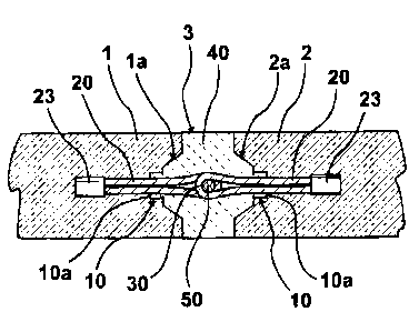
The two pre-cast concrete parts 1 and 2 according to Figure 1 are disposed
at a spacing from one another with formation of a joint 3. The pre-cast
concrete parts 1 and 2 each have a trapezium-shaped recess 1a or 2a at
the end face, wherein provided in the base of the trapezium-shaped recess
CA 02692365 2010-02-10
6
1 a is an insert body 10 which is recognisably constructed to be of U-profile
shape in cross-section. The insert body 10 is cast in place, with surface
flushness, in the end face of the respective wall element 1 or 2. The web 9
of the insert body of U-profile shape has a passage opening 10b for the
cable loop, which is designated overall by 20. The ends of the cable loop
20 are connected together by a pressed member 23, wherein this part of
the cable loop is cast in place in the concrete of the pre-cast concrete part,
just as is the insert body 10. The cable loop 20 overlaps the adjacent cable
loop, wherein the eye 30 thereby formed receives a reinforcing rod 50. The
to joint 3 is then filled with casting mortar 40.
A side illustration of two pre-cast concrete parts connected together is
evident from Figure 2.
The cable loop 20 in the bent-over state of the loop-shaped end is
illustrated from Figure 3. In this connection the two cable sections 21 and
22, which in the region of the bent-over portion (arrow 25) each receive a
sleeve 26, are apparent. The sleeve is made of, for example, plastics
material and is configured in such a manner that it breaks when the cable
loop 20 is bent up in the direction of the arrow 28.
The insert body 10 with a cable loop 20 in bent-over state is depicted in the
illustration according to Figure 4. The insert body 10, which is constructed
to be of U-profile shape, has an opening 10b on its rear side (Figure 5).