Note: Descriptions are shown in the official language in which they were submitted.
CA 02692512 2010-01-04
DESCRIPTION
Transcranial Electrical Stimulation Device
TECNICAL FIELD
The present invention relates to a transcranial
electrical stimulation device capable of accurately
positioning electrodes at predetermined positions of a
patient`shead and capable of effectively stimulating the motor
area of a cerebral cortex.
BACKGROUND ART
A transcranial electrical stimulation method is a method
for electrically stimulating the motor area of a cerebral cortex.
The method was reported by Levy et al. in 1984 (Levy, 1984),
and at the same time, the method was immediately spread all over
the world.
The transcranial electrical stimulation method is widely
used mainly for the purpose of spinal cord lesion segment
diagnosis in a spinal cord disorder or for performing spinal
cord function monitoring during surgery of a spinal cord tumor
and the like (Mckay, 1997) . Since spinal cord lesion segment
diagnosis can functionally diagnose the lesion segment of the
spinal cord disorder, the certainty of the treatment was
dynamically improved.
When there is a danger of causing a spinal cord injury
during a surgery of an intramedullary spinal cord tumor,
scoliosis and the like, spinal cord function monitoring is
essential for performing the surgery safely.
Regarding spinal cord lesion segment diagnosis or spinal
cord function monitoring, there are many reports discussing its
usefulness. With regard to the Applicant of the present
application, there are 600 cases which had performed the
transcranial electrical stimulation method in the past 12 years.
-1-
CA 02692512 2010-01-04
When considering that there are approximately 4500 orthopedic
hospitals in Japan, it is presumed that the number of cases in
which the present method has been performed is large.
However, on the contrary, there also are problems such
as the following.
In the conventional method, in order to stimulate the
motor area of the cerebral cortex, the skull outer layer which
is directly thereon is bored with a drill and a hole is made
to mount a needle electrode.
Although there is no serious report for complications up
till now in the conventional method, time was required to mount
the electrode since the bone had to be bored.
Since there are personal differences in head size, it does
not necessarily mean that an effective motor area of a cerebral
cortex can be stimulated at the first electrode mounting. If
an emission of an evoked potential is difficult, there are cases
where a change in the electrode position is needed.
Therefore, a development is desired for a mounting means
of an electrode which is more easily mountable to the head and
is also minimally invasive.
Japanese Laid-Open Publication No. 9-294815 (Reference
1) discloses a transcranial electrical stimulation device for
outputting currents which are independently adjusted,
respectively, from two electrode pairs.
However, in this device, the electrodes are attached to
the head by a band and the like. The electrodes cannot be
accurately positioned to predetermined positions of a patient's
head.
Japanese Laid-Open Publication No. 7-289649 (Reference
2) discloses a stimulant signal generating device of an
ophthalmic nerve for generating nervous waves in which there
is less weariness and the effect of the treatment is improved.
However, this subject matter does not relate to a transcranial
electrical stimulation device.
Japanese Laid-Open Publication No. 2003-339885
(Reference 3) discloses an electrical stimulating device for
-2-
CA 02692512 2010-01-04
activating scalp capable of preventing the deterioration of
scalp tissues, and reducing headache and symptoms accompanying
therewith, by alleviating the abnormal tension of head part
facial muscles. However, this subject matter also does not
relate to a transcranial electrical stimulation device.
Reference 1: Japanese Laid-Open Publication No. 9-294815
Reference 2: Japanese Laid-Open Publication No. 7-289649
Reference 3: Japanese Laid-Open Publication
No. 2003-339885
DISCLOSURE OF THE INVENTION
Therefore, the present invention may attain the following
purposes.
(1) It is unnecessary to bore a patient's skull outer layer with
a drill. Thus, a transcranial electrical stimulation device
which can perform mounting of the electrode in a short time is
provided.
(2) A transcranial electrical stimulation device capable of
accurately positioning the electrodes at predetermined
positions of a patient's head and capable of effectively
stimulating the motor area of a cerebral cortex is provided.
(3) A transcranial electrical stimulation device having a
mounting means of an electrode which is easily mountable to the
head and is also minimally invasive is provided.
A transcranial electrical stimulation device of the
present invention has a wearing equipment detachably worn on
a patient's head and at least a pair of electrodes attached to
the wearing equipment, and the device is for electrically
stimulating a motor area of a patient's cerebral cortex by
outputting current from the electrode connected to a current
generator, wherein: an engagement part capable of engaging the
wearing equipment to a scalp with a thread-like body is provided
to the wearing equipment; and the electrode is attached to the
-3-
CA 02692512 2010-01-04
wearing equipment protrudably to the head side, and tip of the
electrode is capable of subcutaneously piercing through the
head. Thus, the aforementioned purpose is attained.
In one embodiment, the engagement part is a through hole
provided to the wearing equipment.
In one embodiment, a screw is formed around the electrode,
and the electrode is screwed with the wearing equipment.
In one embodiment, the wearing equipment comprises an
arch-shaped elastic member capable of an elastic deformation.
In one embodiment, the wearing equipment is a plate made
of plastic and the like with elasticity.
In one embodiment, the wearing equipment has a hair band
type shape.
In one embodiment, the thread-like body is a thread or
string.
In one embodiment, a fastening part for securing the
wearing equipment to a patient's head is provided to both sides
of the wearing equipment.
In one embodiment, fixing equipment is fixed to the
wearing equipment, and the electrode is attached, capable of
screwing forward and backward to the fixing equipment.
In one embodiment, the electrode is movable in a
longitudinal direction of the wearing equipment.
According to a transcranial electrical stimulation
device of the present invention, when putting a thread through
the engagement part (for example, hole) of the wearing equipment
and sawing it to the scalp at the head top part of a patient
to secure the engagement part to the head top part, the
electrodes positioned both at left and right sides of the
engagement part are positioned at predetermined positions,
respectively, directed to a patient's cerebral cortex.
Thus, by outputting the current from the electrode, the
motor area of a patient's cerebral cortex can be electrically
stimulated.
In this way, by only wearing the wearing equipment on a
-4-
CA 02692512 2010-01-04
patient's head, the electrodes can be accurately positioned at
predetermined positions of a patient's head so that it can be
effectively stimulating the motor area of a cerebral cortex.
Since the distance between the electrode and the motor area of
a patient's cerebral cortex is approximately constant, the
motor area can be stimulated with a stable potential.
Since it is possible to generate sufficient stimulation
by setting the electrode subcutaneously due to using a screw
electrode, it is unnecessary to bore a patient's skull outer
layer with a drill, and mounting of the electrode can be
performed in a short time. Moreover, it is easily mountable
to the head and is also minimally invasive.
Particularly, the transcranial electrical stimulation
device being constituted by a hair band (one type of hair
accessory) type base part and a needle electrode, the hair band
type plate is made of plastic with elasticity. Thus, the
transcranial electrical stimulation device of the present
invention can be fit to the head in any kind of case without
being affected by the shape and size of the head.
Moreover, the needle electrode is optimized such that it
can effectively stimulate the cerebral cortex only by
subcutaneously piercing without boring the skull outer layer.
Additionally, if a plurality of holes for setting the needle
electrode is formed on the hair band type base, a change in
electrode position is very easy even if an effective stimulation
of the motor area cannot be obtained.
BRIEF DESCRIPTION OF THE DRAWINGS
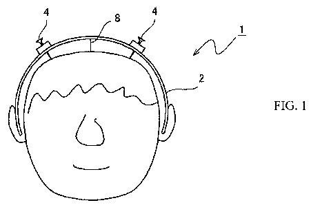
Figure 1 is an explanation view showing a condition of
a transcranial electrical stimulation device which is worn on
a patient's head of one embodiment of the present invention.
Figure 2 is a front view of the condition of a transcranial
electrical stimulation device of Figure 1.
-5-
CA 02692512 2010-01-04
Figure 3 is a perspective view of the condition of a
transcranial electrical stimulation device of Figure 1.
Figure 4 is a top view showing a mounting condition of
the condition of a transcranial electrical stimulation device
of Figure 1.
Figure 5 is an enlarged view of a part of the transcranial
electrical stimulation device of Figure 1.
Figure 6 is an explanation view showing a condition that
the electrode of the transcranial electrical stimulation device
is inserted a cerebral cortex.
Figure 7 is a diagram of another embodiment of an
transcranial electrical stimulation device.
BEST MODES FOR CARRING OUT THE INVENTION
The embodiments of the present invention are described
with reference to the drawings.
As shown in Figures 1-4, a transcranial electrical
stimulation device 1 comprises a wearing equipment 2 which is
detachably worn on a patient's head, and at least a pair of
electrodes 4 attached to the wearing equipment 2.
The wearing equipment 2 comprises an arch-shaped plate
capable of an elastic deformation. The wearing equipment 2 can
be formed of an electrical insulating plastic with elasticity,
and also can be constituted by a metal plate and the like. When
forming the wearing equipment 2 with a metal plate, it is
preferable to cover the surface of the metal plate with an
electrical insulating resin.
Fastening parts 12 for securing the wearing equipment 2
onto a patient's head can be provided to both ends of the wearing
equipment 2. The fastening parts 12 can be constituted by a
sheet-like fastener. In that case, a chin strap having a
-6-
CA 02692512 2010-01-04
sheet-like fastener provided to both ends is used. By fastening
the sheet fastener of the chin strap to the fastening parts 12
of the wearing equipment 2, the wearing equipment 2 can be
secured to the head.
As shown in Figure 7, curved parts 14 may be provided to
both ends of the wearing equipment 2 such that the wearing
equipment 2 can be attached to or detached from the ears or both
sides of the head.
An engagement part 6 capable of engaging the wearing
equipment 2 to a patient's scalp with a thread-like body 8 is
provided to an approximate central part in a horizontal
direction of the wearing equipment 2. The thread-like body 8
can be constituted by a thread or string.
The engagement part 6 may be a through-hole or a protrusion
provided to the wearing equipment 2. The position of the
through-hole 6 is provided to a place where the through-hole
6 is positioned at the head top part when wearing the wearing
equipment 2 onto the head.
A pair of electrodes 4,4 are attached to the wearing
equipment 2. When constituting the wearing equipment 2 with
an arch-shaped plate, the electrodes 4 are attached to fixing
parts 10 which are fixed to an outer surface of the plate.
The fixing appliances 10 are constituted into a
disc-shape with an electrical insulating resin and the like,
and holes 11 are formed at the central parts thereof.
Through-holes (not shown) are formed on the plate of the wearing
equipment 2 corresponding to the holes 11.
The electrode 4 is formed with a screw, and by screwing
it into the hole 11 of the fixing equipment 10 and the hole of
the wearing equipment 2, the electrode 4 is attached by having
the protruding dimension towards the head adjustable.
As shown in Figure 4, it is preferable to provide the
electrode 4 to a position which is 4.5-5.5cm apart in a
horizontal direction (Ll) and 1.5-2.5cm apart in a forward
direction (L2) with respect to the engagement part 6. Typically,
it is provided to a position which is 5cm apart in a horizontal
-7-
CA 02692512 2010-01-04
direction and 2cm apart in a forward direction with respect to
the engagement part 6. When applying the stimulation device
of the present invention to a child, a pair of electrodes 4,4
may be provided to a position which is horizontally 3cm from
the engagement part 6. These dimensions can be arbitrarily set
by considering the size, sex, age and the like of a patient's
head.
By positioning the engagement part 6 of the wearing
equipment 2 at the top of a patient' s head, the electrode 4 is
directed to the motor area of a patient's cerebral cortex.
A female screw corresponding to a male screw of the
electrode 4 may be formed inside the hole of the fixing equipment
10.
The screw is not provided to the tip 5 of the electrode
4, and it is approximately conical or conical trapezoid.
Materials for electrodes to be used may include those
which are conventionally known. For example, platinum, silver,
copper, stainless, gold or a matter which is a gold-plated
conductor may be used. Particularly, gold and gold-plated
matters are preferable.
The pair of electrodes 4 is connected to a conventionally
known current generator (not shown) with a code. The motor area
of a patient's cerebral cortex can be electrically stimulated
by outputting currents from the electrodes 4. The current
generator generates currents including pulses. A controlling
means for adjusting and controlling the currents is connected
to the current generator, and the controlling means adjusts the
current amplitude, pulse duration, pulse frequency and the
like.
Next, a method for electrically stimulating the motor
area of a patient's cerebral cortex using the transcranial
electrical stimulation device 1 of the aforementioned
configuration is described.
As shown in Figures 1 and 4, the wearing equipment 2 is
mounted to a patient's head. Herein, when providing fastening
parts 12 to both ends of the wearing equipment 2, the tightening
-8-
= CA 02692512 2010-01-04
member such as a band, strap or string is under the patient's
chin to secure the fastening parts 12. Since the wearing
equipment 2 is elastic, it can adapt to various sizes of the
patients' heads.
A,thread 8 is put through the through-hole 6 provided to
the wearing equipment 2 to saw it into the scalp at the top of
a patient's head. Due to this, the central part of the wearing
equipment 2 is nearly secured to the top of a patient's head.
Simultaneously, the positions of both electrodes 4,4 are
positioned at predetermined locations of a patient's head.
Next, the electrode 4 is rotated to proceed the tip 5
subcutaneously 16. As the electrode 4 protrudes towards the
head, the wearing equipment receives a counteraction and tries
to draw away from the head. However, the central part of the
wearing equipment 2 is secured with a thread 8 and the like at
the top of the head as described above. Thus, the central part
of the wearing equipment 2 does not greatly separate from the
head, and accordingly, the tip of the electrode 4 is inserted
subcutaneously.
The tip part of the electrode 4 is inserted subcutaneously
16 for approximately 4-5mm. Herein, since the screw is formed
around the electrode 4, the electrode 4 contacts the
subcutaneous tissue of the head by a wide contact area. In this
state, the current is output from the electrode 4 connected to
the current generator to electrically stimulate the motor area
of a patient's cerebral cortex.
In this way, by outputting the current from the electrode
4 in a state where the electrode 4 is sufficiently in contact
with the subcutaneous tissue, the cerebral cortex can be
effectively stimulated.
In the aforementioned embodiment, holes for setting the
electrodes 4 to the wearing equipment 2 were formed at two places
at both sides of the engagement part 6. However, they may be
formed at several places. Moreover, the electrodes may be
constituted according to the head size, sex and age such that
they move along the plate of the wearing equipment. For example,
-9-
CA 02692512 2010-01-04
a long hole may be provided to the plate of the wearing equipment
to slidably stop the electrode at the long hole.
INDUSRIAL APPLICABILITY
According to the present invention, it is unnecessary to
bore a patient's skull outer layer with a drill. Thus, a
transcranial electrical stimulation device which can perform
mounting of the electrode in a short time is provided. The
device is capable of accurately positioning the electrodes at
predetermined positions of a patient's head and capable of
effectively stimulating the motor area of a cerebral cortex.
The device is easily mountable to the head and is also minimally
invasive.
-10-